
Related Manuals for Festo CPV10-GE-IBL-8


Summary of Contents for Festo CPV10-GE-IBL-8
- Page 1 Compact Performance CPV valve terminal with direct connection Electronics Field bus protocol: INTERBUS-Loop Direct connection type CPV..-GE-IBL-...
- Page 2 Type: DUCOM Edition: 9809NH © (Festo AG & Co., 73726 Esslingen, Federal Republic of Germany, 1998) The copying, distribution and utilization of this docu- ment as well as the communication of its contents to others without expressed authorization is prohibited. Of- fenders will be held liable for the payment of damages.
- Page 3 Contents and safety instructions Order no.: 175509 Title: Manual Designation: P.BE-CP-IBL-GB CP-IBL 9809NH...
-
Page 4: Table Of Contents
Contents and safety instructions Contents Designated use..........V Target group . - Page 5 Contents and safety instructions 3. Diagnosis Summary of diagnostic possibilities ..... . 3-3 Diagnosis via LEDs ........3-4 3.2.1 Normal operating status .
-
Page 6: Designated Use
Contents and safety instructions Designated use The CPV valve terminal type CPV-... with direct con- nection to the INTERBUS-Loop type CPV..-GE-IBL-... described in this manual is intended exclusively for use as a slave on the INTERBUS-Loop and compatible field buses. The CPV valve terminal may only be used as follows: –... -
Page 7: Notes On This Manual
Contents and safety instructions Notes on this manual PLEASE NOTE This manual describes the functioning of the soft- ware version 1.x and the hardware version 04/98 of the CPV valve terminal with direct connection to the INTERBUS-Loop. This manual contains specific information on installing, commissioning, configuring and diagnosing CPV valve terminals with direct connection for the INTERBUS- Loop. -
Page 8: Important User Instructions
Contents and safety instructions Important user instructions Danger This manual contains instructions categories possible dangers which may arise if the valve terminal is not used correctly. These instructions are printed in italics, surrounded by a frame and also marked with a pictogram. - Page 9 Contents and safety instructions Pictograms Pictograms and symbols complement the danger warn- ings and draw attention to the nature and conse- quences of dangers. The following pictograms are used: Uncontrolled movements of loose tubing. Uncontrolled movement of the connected actuators. High electric voltage or undefined switching states of the electronic components which affect the connected circuits.
-
Page 10: Installation
1. Installation Chapter 1 Installation CP-IBL 9809NH... - Page 11 1. Installation Contents 1. Installation General notes on installation ......1-3 Description of the product ......1-4 Structure of the INTERBUS-Loop .
-
Page 12: General Notes On Installation
1. Installation 1.1 General notes on installation WARNING Before undertaking installation and maintenance work, switch off the following: • the compressed air supply • the operating voltage supply to the bus terminal • the load voltage supply to the CPV valves You can thereby avoid: –... -
Page 13: Description Of The Product
1. Installation 1.2 Description of the product CPV valve terminal type CPVxx-GE-IBL is a valve ter- minal for connecting to the INTERBUS-Loop. It enables control of maximum 16 valve coils (single or double solenoid valves) per valve terminal. It is distinguished by the following features: –... -
Page 14: Structure Of The Interbus-Loop
1. Installation 1.3 Structure of the INTERBUS-Loop The diagram below shows the basic structure of an IN- TERBUS-Loop ring. CPV ...-IBL valve terminal Valve coil status LED BUS IN connection Blind plug for valve supply " BUS OUT connection INTERBUS-Loop return cable Diagnosis/status LEDs Bus terminal for INTERBUS-Loop INTERBUS-Loop incoming cable... -
Page 15: Pin Assignment
1. Installation 1.4 Pin assignment The diagram below shows the bus and valve supply connections and their assignment. Bus IN + Bus IN - " Bus OUT + Bus OUT - 24 V DC valve supply 0 V valve supply Earth connection for valve supply Fig. -
Page 16: Connecting The Cpv Valve Terminal
1. Installation 1.5 Connecting the CPV valve terminal 1.5.1 Structure of the Quickon screw connector The diagram below shows the structure of the Quickon- screw connector. Union nut Crown " Sealing rubber Cable cores Insulation removed (15 mm) Splicing ring (2-pin for bus, 3-pin for valve supply) Fig. -
Page 17: Preparing The Connecting Cable
1. Installation 1.5.2 Preparing the connecting cable Prepare and connect the cable as follows: • Push the union nut, the crown and the sealing rubber onto the cable. Remove approximately 15 mm of the insulation from the cable (points A and B). PLEASE NOTE You must observe the cable specifications in the ap- pendix of this manual and in your controller manual. - Page 18 1. Installation Fig. 1/4: Mounting sequence for Quickon screw connectors CP-IBL 9809NH...
-
Page 19: Connecting The Cables
1. Installation 1.5.3 Connecting the cables • Insert the prepared cable into the appropriate con- nection on the CPV terminal (A). • Turn the connection until the codings fit exactly into the appropriate guides. The codings on the splicing rings prevent connection being made with the incor- rect polarity (BUS IN –... -
Page 20: Fitting The Blind Plug
1. Installation 1.5.4 Fitting the blind plug PLEASE NOTE If you do not use the connection for the continuing- valve supply, cover it with a blind plug (see Fig. 1.6). The blind plug is included in delivery the Quickon set, see Appendix A, accessories. Proceed as follows: •... - Page 21 1. Installation Union nut Blind plug " Crown Sealing rubber Splicing ring Fig. 1/6: Fitting the blind plug 1-12 CP-IBL 9809NH...
-
Page 22: Selecting The Power Unit
By using PELV power units, protection against electric shock (protection against direct and indirect contact) in accordance with EN 60204-1/IEC 204 is guaranteed on Festo valve terminals. Safety transformers with the adjacent designation must be used for supplying PELV networks. The valve termi- nals must be earthed in order to ensure their function (e.g. - Page 23 1. Installation Total current The following table shows you how to calculate the total consumption current consumption for an INTERBUS-Loop ring. The values specified have been rounded up. Bus current consumption CPV..-IBL-... Sums CPV valve terminal 50 mA Number of valve terminals ______ = ______ mA Current consumption of valve supply...
-
Page 24: Notes On Connecting The Operating Voltage
1. Installation 1.5.6 Notes on connecting the operating voltage CAUTION Fuse the load voltage of the CPV valve coils exter- nally with max. 2 A. The supply to the electronic com- ponents (via the INTERBUS-Loop) must be fused ex- ternally. With the external fuse you can avoid functional dam- age to the CPV valve terminal if there is a short cir- cuit. - Page 25 1. Installation The current consumption depends on the type of valve coil. The values can be found in the "Pneumatics ma- nual, P.BE-CPV-.." PLEASE NOTE Check your EMERGENCY STOP circuit to ascertain which measures are necessary for putting your ma- chine or system into a safe state if there is an EMER- GENCY STOP (e.g.
- Page 26 1. Installation The load voltage supply for the CPV valve terminals is usually looped through ( ). If the voltage on the supply cable drops below the minimum value (load voltage < 20.6 V), the supply can also be made star-shaped ( ).
-
Page 27: Earthing
1. Installation 1.5.7 Earthing The CPV valve terminal has 2 functional earth connec- tions: • on the load voltage connection of the CPV valve ter- minal • on the left-hand end plate PLEASE NOTE • Always connect the earth potential to the load voltage connection. -
Page 28: Commissioning
2. Commissioning Chapter 2 Commissioning CP-IBL 9809NH... - Page 29 2. Commissioning Contents 2. Commissioning Commissioning on an INTERBUS master ....2-3 2.1.1 General ......... . . 2-4 Switching on the operating voltage .
-
Page 30: Commissioning On An Interbus Master
2. Commissioning 2.1 Commissioning on an INTERBUS master This chapter describes the configuration and addressing of a CPV valve terminal with INTERBUS-Loop connec- tion to an INTERBUS master or compatible master. A general and comprehensive description can be found in the appropriate manual for the CMD software. -
Page 31: General
2. Commissioning 2.1.1 General Before commissioning or programming, you should compile a configuration list of all connected field bus slaves. On the basis of this list you can: • • carry out a comparison between NOMINAL and AC- TUAL configurations in order to recognize connection faults. - Page 32 2. Commissioning When you switch your controller on, it automatically car- ries out a comparison between the NOMINAL and the ACTUAL comparisons. The following are important for this comparison: • • The specifications on configuration must be complete and correct. •...
-
Page 33: Addressing Variants
2. Commissioning 2.3 Addressing variants The CPV valve terminal with INTERBUS-Loop supports the following addressing variants, depending on the module and PLC used: – configuration via the CMD software – logical addressing – physical addressing The individual addressing variants are explained in de- tail below. -
Page 34: Bus Configuration
2. Commissioning • • Select the appropriate values for the ID code and the process data channel. Type Ident code Process data channel (outputs) CPV10-GE-IBL-8 16 bits CPV14-GE-IBL-4 8 bits CPV14-GE-IBL-8 16 bits 2.5 Bus configuration 2.5.1 Bus configuration with CMD software... -
Page 35: Inserting With The Ident Code
2. Commissioning Inserting with the Ident code • • Open the dialogue window of the bus terminal for the INTERBUS-Loop. Select the option "Insert with Ident code.." Fig. 2/1: Inserting bus slaves with the Ident code CP-IBL 9809NH... - Page 36 Enter 8 or 16 bits under "Process data channel," de- pending on the type of your valve terminal. Type Ident code Process data channel (outputs) CPV10-GE-IBL-8 16 bits CPV14-GE-IBL-4 8 bits CPV14-GE-IBL-8 16 bits • • Slave type: The default entry Local bus device can be entered.
-
Page 37: Insert Slave Description
2. Commissioning Insert slave description In the following input mask you can describe the slave and enter specific information on the CPV valve termi- nal, e.g. station name and a picture of the slave. Fig. 2/3: Dialogue window "Insert Device Description" 2-10 CP-IBL 9809NH... - Page 38 The specific icons of the Festo valve terminals can be found on the accompanying CD-ROM. • • Read the text "Readme.txt" on the CD-ROM, for a quick survey of the contents of the CD-ROM. • • Copy the file "Festo.ICL" into the CMD directory \PICTURE\. 2-11 CP-IBL 9809NH...
- Page 39 • • Change from one installed icon file to the other with the box "Select .." • • Select the file Festo.ICL. • • Mark icon 6 (it corresponds to your CPV valve termi- nal for the INTERBUS-Loop).
- Page 40 2. Commissioning The icons are numbered. The following table shows the relationship between the number of the icon and the valve terminal type. Icon no. Valve terminal type Type 10 Types 03-05 with inputs and outputs Types 03-05 only with valves and/or outputs Type 02 with inputs and outputs Type 02 only with valves Type 10 CPV with INTERBUS-Loop...
-
Page 41: Bus Configuration Without Cmd Software
2. Commissioning 2.5.2 Bus configuration without CMD software 2.5.3 Logical addressing PLEASE NOTE Configure a CPV valve terminal as follows: • • ID CODE: 177D (B2Hex) • • Process data channel: 8 or 16 bits • • Number of outputs: 8 or 16 •... - Page 42 • • Assign a logical OUT address and, depending on the type of your valve terminal, 8 or 16 bit outputs to each CPV valve terminal. Type Ident code Process data channel (outputs) CPV10-GE-IBL-8 16 bits CPV14-GE-IBL-4 8 bits CPV14-GE-IBL-8 16 bits 2-15...
-
Page 43: Physical Addressing
PLEASE NOTE Depending on the type of valve terminal, the CPV valve terminal occupies 8 or 16 outputs. Type Ident code Process data channel (outputs) CPV10-GE-IBL-8 16 bits CPV14-GE-IBL-4 8 bits CPV14-GE-IBL-8 16 bits 2-16 CP-IBL 9809NH... - Page 44 2. Commissioning Example of physical addressing: – 1st. slave: 32 inputs/32 outputs, – 2nd. slave: bus terminal IBS SL 24.., – 3rd.- 5th. slave: CPV10 valve terminals with 16 outputs 1st. slave 2nd. slave 3rd. slave 4th. slave 5th. slave xxx2 IBS SL 24 ..
-
Page 45: Basic Rules For Addressing Cpv Valve Terminals
2. Commissioning 2.6 Basic rules for addressing CPV valve terminals Depending on the type of valve terminal, the CPV valve terminal occupies 8 or 16 outputs. This enables the CPV valve terminal to be extended at a later stage without the need to shift the addresses. The following diagram shows the addressing sequence of the individual CPV valve plates. -
Page 46: Addressing The Cpv Valve Terminal
2. Commissioning 2.6.1 Addressing the CPV valve terminal Further information on addressing can be found in the manuals for your controller and the INTERBUS-Loop. The address assignment (process data assignment) of the outputs/coils of a CPV valve terminal on the IN- TERBUS-Loop or compatible system depends firstly on the INTERBUS module and on the control system used. - Page 47 2. Commissioning The following examples give basic information on the different address assignments and the position of the low byte (n) and the high byte (n+1). A distinction is made here between the: • • Siemens mode and the • • Standard mode Example: –...
-
Page 48: Example Of Siemens Mode
2. Commissioning Example of Siemens mode The following diagram shows the assignment of the CPV valve coils to the addresses in Siemens mode. Fig. 2/6: Assignment of the valve coils (Siemens mode) 2-21 CP-IBL 9809NH... -
Page 49: Example Of Standard Mode
2. Commissioning Example of Standard mode The following diagram shows the assignment of the CPV valve coils to the addresses in standard mode. Fig. 2/7: Assignment of the valve coils (Standard mode) 2-22 CP-IBL 9809NH... -
Page 50: Process Data Entry Via The Cmd Software
2. Commissioning 2.6.2 Process data entry via the CMD software As from version 4.x, the CMD software offers the possi- bility of assigning any output to the PLC/IPC within the configured address range of the valve coil. In order to do this, proceed as follows: •... - Page 51 2. Commissioning In the following menu you can determine the I/O ad- dresses (example: Siemens mode, byte-by-byte assign- ment for an S5). Fig. 2/9: Entering process data – example of Siemens mode PLEASE NOTE You need only swap the assigment of the two bytes in order to correct the byte swap.
-
Page 52: Preprocessing
PLEASE NOTE All the valves on a CPV valve terminal can be prepro- cessed. 2.8 Periphery fault (PF) The Festo CPV valve terminal on the INTERBUS-Loop does not generate a periphery fault. 2-25 CP-IBL 9809NH... - Page 53 2. Commissioning 2-26 CP-IBL 9809NH...
-
Page 54: Diagnosis
3. Diagnosis Chapter 3 Diagnosis CP-IBL 9809NH... - Page 55 3. Diagnosis Contents 3. Diagnosis Summary of diagnostic possibilities ..... . 3-3 Diagnosis via LEDs ........3-4 3.2.1 Normal operating status .
-
Page 56: Summary Of Diagnostic Possibilities
3. Diagnosis 3.1 Summary of diagnostic possibilities The CPV valve terminal with connection to the IN- TERBUS-Loop offers the following possibilities of diag- nosis and fault treatment: a) diagnosis via the built-in LEDs (see Chapter 3.2). – bus status (DIAG, green) –... -
Page 57: Diagnosis Via Leds
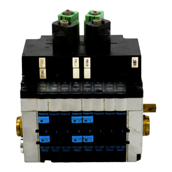
3. Diagnosis 3.2 Diagnosis via LEDs The LEDs on the CPV valve terminal indicate the oper- ating and/or error status. Bus status/error LED "DIAG" Operating voltage LED "US" Valve status display Fig. 3/1: Diagnosis LEDs of the CPV valve terminal CP-IBL 9809NH... -
Page 58: Normal Operating Status
3. Diagnosis 3.2.1 Normal operating status In the normal operating status the DIAG LED and the US LED light up. ( = lights up; = flashes; = out) Status Sequence Operating status Error treatment DIAG Normal None Normal None 3.2.2 Error display (US) This "US"... -
Page 59: Error Display (Diag)
3. Diagnosis 3.2.3 Error display (DIAG) Error displays of the green LED "DIAG": Status Sequence Operating status Error treatment • Start bus DIAG – INTERBUS inactive • Eliminate interruption – Bus interruption • Current consumption – Excess temperature on INTERBUS in ring too high protocol chip LPC2 - Reduce current... -
Page 60: Displays Of The Valve Coils
3. Diagnosis 3.2.4 Displays of the valve coils There is a yellow LED for every valve solenoid coil. This LED indicates the operating status of the relevant valve solenoid coil. Yellow LED row for pilot solenoid 14 Yellow LED row for pilot solenoid 12 Fig. -
Page 61: Diagnosis Via Interbus
3. Diagnosis 3.3 Diagnosis via INTERBUS The CPV valve terminal with connection to the TERBUS-Loop supports the INTERBUS typical diag- nosis via: • • the diagnostic status register and • • the diagnostic parameter register The following error messages are entered in the diag- nostic register: –... -
Page 62: Error Treatment
3. Diagnosis 3.4 Error treatment 3.4.1 Reaction to faults in the control system The CPV valves are switched off after 25 ms when there is a bus interruption. PLEASE NOTE If the outputs are reset after a PLC stop or a field bus interruption, note the following in respect of the pneumatic valves: –... - Page 63 3. Diagnosis 3-10 CP-IBL 9809NH...
-
Page 64: Technical Appendix
A. Technical appendix Appendix A Technical appendix CP-IBL 9809NH... - Page 65 A. Technical appendix Contents A. Technical appendix Technical specifications of the CPV valve terminal with direct link to the INTERBUS-Loop type CPV..-GE-IBL-..A-3 Accessories......... A-5 Connection to the INTERBUS-Loop.
-
Page 66: Technical Specifications Of The Cpv Valve Terminal With Direct Link To The Interbus-Loop Type Cpv
A. Technical appendix A.1 Technical specifications of the CPV valve terminal with direct link to the INTERBUS-Loop type CPV..-GE-IBL-... General Temperature range: – operation C ... + 50 – storage C ... + 70 Relative humidity 95%, non-condensing Protection class as per EN 60 529 IP 65 Connector plugged in or fitted with protective cap... - Page 67 – Current consumption 48 mA – Protection against incorrect via bridge-connected rectifier polarity – Electrical isolation from valves Identification in the INTERBUS CPV10-GE-IBL-8/CPV14-GE-IBL-8: – Identification code (ID) hex. – Address range (outputs) 16 Bit (process data channel) – PCB address range –...
-
Page 68: Accessories
The connections to the bus and to the load voltage are made in the form of Quickon screw connectors. You can order a complete set (each for one CPV valve ter- minal) from Festo. Type: Connection set, part no. 175 485 Further accessories... -
Page 69: Dimensions
A. Technical appendix A.3 Dimensions Dimensions of CPV basic unit with INTERBUS-Loop di- rect connection Type CPC10-GE-IBL-8 71 mm 64 mm 110 mm CPC14-GE-IBL-4 89 mm 64 mm 96 mm CPC14-GE-IBL-8 89 mm 64 mm 152 mm CP-IBL 9809NH... - Page 70 A. Technical appendix CP-IBL 9809NH...
- Page 71 B. Index Appendix B Index CP-IBL 9809NH...
- Page 72 B. Index CP-IBL 9809NH...
- Page 73 B. Index Accessories ....... . A-5 Address assignment ....2-19 - 2-20 Addressing CP valve terminals .
- Page 74 Faults in the control system....3-9 Icons of the Festo valve terminals....2-11 ID code.
- Page 75 B. Index Quickon screw connector ..... 1-7 Quickon screw connectors..... A-5 Switching-on instructions .
- Page 76 B. Index CP-IBL 9809NH...
Need help?
Do you have a question about the CPV10-GE-IBL-8 and is the answer not in the manual?
Questions and answers