Table of Contents
Advertisement
SETUP & OPERATION MANUAL
FEATURES
Adjustable spindle tension return spring.
Built-in laser pointer.
Sturdy design with cast-iron head, base, and
table.
High-quality bearings for smooth, vibration-free
operation.
Simple hand lever controlled mechanical
variable speed from 280 to 2100 rpm.
Digital spindle speed display.
Industrial-quality 120 V motor.
Chuck with key.
Easy to use see-through flip-up chuck guard
included.
Crank-operated rack and pinion table height-
adjustment.
SPECIFICATIONS
• Swing
15" (390 mm) - # 75-155
17" (430 mm) - # 75-165
20" (515 mm) - # 75-510
• Drilling capacity / Chuck size
3/4" (20 mm) / 5/8" (16 mm) - # 75-155
1 1/8" (28 mm) / 5/8" (16 mm) - # 75-165
1 1/4" (32 mm) / 3/4" (20 mm) - # 75-510
• Spindle travel
3 1/8" (80 mm) - # 75-155/165
4 3/4" (120 mm) - # 75-510
• Spindle distance to table / to base
29 3/8" (745 mm) / 48 1/2" (1230 mm) - # 75-155
29" (735 mm) / 48 5/8" (1235 mm) - # 75-165
27 3/4" (705 mm) / 46 7/8" (1190 mm) - # 75-510
• Table size
(Diameter) 12 3/8" (315 mm) - # 75-155
13 3/16" x 13 3/16" (335 x 335 mm) - # 75-165
18 3/4" x 16 3/4" (475 x 425 mm) - # 75-510
• Column diameter
2 3/4" (70 mm) - # 75-155
3 1/8" (80 mm) - # 75-165
3 5/8" (92 mm) - # 75-510
• Spindle speeds
(Variable speed) - 280 to 2100 rpm
• Spindle taper
MT 2 - # 75-155 / MT 3 - # 75-165/510
• Overall height
63 3/8" (1610 mm) - # 75-155
64 3/8" (1635 mm) - # 75-165
67" (1700 mm) - # 75-510
• Base size
17" x 10 1/2" (430 x 265 mm) - # 75-155
20 1/4" x 12" (515 x 303 mm) - # 75-165
23 5/8" x 15 3/4" (600 x 400 mm) - # 75-510
• Motor
1/2 HP , 120 V, 5A - # 75-155
3/4 HP , 120 V, 6,5A - # 75-165
1 HP , 120 V, 10A - # 75-510
• Weight
136 lbs (62 kg) - # 75-155
161 lbs (73 kg) - # 75-165
284 lbs (129 kg) - # 75-510
Version
1_Revision
4 - Mai 2016
#
#
© Copyright General International
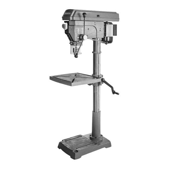
15", 17" & 20" DRILL PRESSES
-
VARIABLE SPEED
MODELS
75-155
#
75-165
#
75-510
#
Advertisement
Table of Contents

Related Manuals for General International 75-155


Summary of Contents for General International 75-155
- Page 1 4 3/4" (120 mm) - # 75-510 • Spindle distance to table / to base 29 3/8" (745 mm) / 48 1/2" (1230 mm) - # 75-155 29" (735 mm) / 48 5/8" (1235 mm) - # 75-165 27 3/4" (705 mm) / 46 7/8" (1190 mm) - # 75-510 •...
- Page 2 8360 Champ-d’Eau, Montreal (Quebec) Canada H1P 1Y3 Telephone (514) 326-1161 • Fax (514) 326-5555 • www.general.ca THANK YOU for choosing this General® International model 75-155, 75-165 or 75-510 drill press. This drill press has been carefully tested and inspected before shipment and if properly used and maintained, will provide you with years of reliable service.
- Page 3 GENERAL INTERNATIONAL WARRANTY ® All component parts of General International and Excalibur by General International products ® ® are carefully inspected during all stages of production and each unit is thoroughly inspected upon completion of assembly. Limited Lifetime Warranty Because of our commitment to quality and customer satisfaction, General International agrees to ®...
-
Page 4: Table Of Contents
Adjusting the chuck guard height ........................17 Adjusting the depth stop ..........................17 Table swing adjustment ........................... 18 Pivoting the table (model 75-155 & 75-165 only) ..................18 Adjusting table height ............................18 Table tilt adjustment ............................19 Drill speed adjustment ............................. 19 Guidelines for selecting speeds based on bit size and bit material ............ -
Page 5: Rules For Safe Operation
RULES FOR SAFE OPERATION To help ensure safe operation, please take a moment to learn the machine’s applications and limitations, as well as potential hazards. General International disclaims any real or implied warranty and hold itself ® harmless for any injury that may result from the improper use of it’s equipment. Do not operate the drill press when tired, distract- able work piece support if the work piece does ed, or under the effects of drugs, alcohol or any... -
Page 6: Electrical Requirements
ELECTRICAL REQUIREMENTS BEFORE CONNECTING THE MACHINE TO THE POWER SOURCE, VERIFY THAT THE VOLTAGE OF YOUR POWER SUPPLY CORRESPONDS WITH THE VOLTAGE SPECIFIED ON THE MOTOR I.D. NAMEPLATE. A POWER SOURCE WITH GREATER VOLTAGE THAN NEEDED CAN RESULT IN SERIOUS INJURY TO THE USER AS WELL AS DAMAGE TO THE MACHINE. -
Page 7: Identification Of Main Parts And Components
IDENTIFICATION OF MAIN PARTS AND COMPONENTS Model 75-165 shown BASE SWITCH COLUMN PULLEY COVER TABLE PIVOT LOCK LEVER* MOTOR TABLE FEED HANDLE FLIP-UP CHUCK GUARD TABLE CRANK HANDLE LASER POINTER SWITCH RACK DIGITAL SPEED DISPLAY *Except on the model 75-510... -
Page 8: Unpacking
UNPACKING Carefully unpack and remove the unit and its components from the box and check for missing or damaged items as per the list of contents below. NOTE: PLEASE REPORT ANY DAMAGED OR MISSING ITEMS TO YOUR GENERAL® INTERNATIONAL DISTRIBUTOR IMMEDIATELY. LIST OF CONTENTS HEAD STOCK ................ -
Page 9: Cleaning
PLACEMENT WITHIN THE SHOP / SAFETY ZONE THIS DRILL PRESS MODEL (1) 75-155, (2) 75-165 OR (3) 75-510 IS HEAVY. DO NOT OVER-EXERT. A HOIST OR FORK- LIFT WITH STRAPS SHOULD BE USED TO LIFT THIS MACHINE. TO LIMIT THE RISK OF SERIOUS INJURY OR DAMAGE TO THE MACHINE, ANY EQUIPMENT USED TO LIFT THIS MACHINE SHOULD HAVE A RATED CAPACITY IN EXCESS OF THE MACHINE. -
Page 10: Assembly Instructions
ASSEMBLY INSTRUCTIONS BEFORE ASSEMBLING, MAKE SURE THAT THE SWITCH IS IN THE “OFF” POSITION AND THAT THE POWER CORD IS UNPLUGGED. DO NOT PLUG IN OR TURN ON THE MACHINE UNTIL YOU HAVE COMPLETED THE ASSEMBLY AND INSTALLATION STEPS DESCRIBED IN THIS SECTION OF THE MANUAL. INSTALLING THE COLUMN ON THE BASE Set the base on a flat and stable surface, and then Align the mounting holes in the column with the... -
Page 11: Installing The Table
Center the head stock with the column and the ing screws A & B using a 5 mm Allen key. table. INSTALLING THE TABLE (75-155/165 ONLY) Make sure that arbor C is to the right and the table Hold the arm against the bracket aligning the bracket is centered on the column. - Page 12 MAKE SURE THE MACHINE HAS BEEN TURNED OFF AND UNPLUGGED FROM THE POWER SOURCE BEFORE PERFORM- ING ANY MAINTENANCE OR ADJUSTMENTS. INSTALLING THE TABLE (75-155/165) Insert the table into the arm mount as shown. Tighten the arm's mounting bolt using a 24 mm wrench.
-
Page 13: Installing The Table (Model 75-510 Only)
MAKE SURE THE MACHINE HAS BEEN TURNED OFF AND UNPLUGGED FROM THE POWER SOURCE BEFORE PERFORM- ING ANY MAINTENANCE OR ADJUSTMENTS. INSTALLING THE TABLE (MODEL 75-510 ONLY) Align the smallest mounting hole in the table with Insert the threaded centering pin A into the small- est hole of the table bracket as shown the pin. -
Page 14: Installing The Chuck Guard
MAKE SURE THE MACHINE HAS BEEN TURNED OFF AND UNPLUGGED FROM THE POWER SOURCE BEFORE PERFORM- ING ANY MAINTENANCE OR ADJUSTMENTS. INSTALLING THE CHUCK GUARD Slide the chuck guard onto its support as shown A. Tighten the chuck guard using a phillips screw- driver. -
Page 15: Installing The Chuck
MAKE SURE THE MACHINE HAS BEEN TURNED OFF AND UNPLUGGED FROM THE POWER SOURCE BEFORE PERFORM- ING ANY MAINTENANCE OR ADJUSTMENTS. INSTALLING THE CHUCK Lift the chuck guard as shown. Clean inside the chuck with a dry cloth until all grease or lubricant is removed. -
Page 16: Removing The Chuck
MAKE SURE THE MACHINE HAS BEEN TURNED OFF AND UNPLUGGED FROM THE POWER SOURCE BEFORE PERFORM- ING ANY MAINTENANCE OR ADJUSTMENTS. REMOVING THE CHUCK Using feed handle, lower the quill assembly A. In- While holding onto the chuck, tap gently on the sert the drift key B all the way into the quill assem- key with a hammer or rubber mallet to loosen and bly C. -
Page 17: On/Off Power Switch
MAKE SURE THE MACHINE HAS BEEN TURNED OFF AND UNPLUGGED FROM THE POWER SOURCE BEFORE PERFORM- ING ANY MAINTENANCE OR ADJUSTMENTS. ON/OFF POWER SWITCH This drill is equipped with a forced opening line interrupter switch located on the front which requires machine restart in case of power failure or circuit interruption. -
Page 18: Pivoting The Table (Model 75-155 & 75-165 Only)
Note: When working with taller work pieces swing the ta- ble 180° out of the way and use the base as a table. PIVOTING THE TABLE (MODEL 75-155 & 75-165 ONLY) Loosen the pivot lock handle as shown. Turn the table to the desired position, and then re- tighten the pivot lock handle. -
Page 19: Drill Speed Adjustment
MAKE SURE THE MACHINE HAS BEEN TURNED OFF AND UNPLUGGED FROM THE POWER SOURCE BEFORE PERFORM- ING ANY MAINTENANCE OR ADJUSTMENTS. TABLE TILT ADJUSTMENT Note: For the model 75-510 remove the threaded centering pin under the table before completing the following steps. Loosen nut A Tilt the table to the desired angle, and then retight- en the nut A. -
Page 20: Operating Instructions
OPERATING INSTRUCTIONS CHECKLIST BEFORE STARTING VERIFY ALL CHECK POINTS BEFORE STARTING. FAILURE TO COMPLY CAN RESULT IN SERIOUS INJURIES. • Make sure the pulley cover is closed. • Check that the chuck is installed properly. • Make sure the chuck guard is securely installed and closed properly. •... -
Page 21: Maintenance
MAINTENANCE BELT REPLACEMENT Inspect the belts afler every 100 hours of use. Belts that show visible signs of wear such as cracks or fraying at the edges should be replaced immediately. Unplug the machine, and open the pulley cover as Note: To replace belt A, remove belt B first. -
Page 22: Lubrication
MAKE SURE THE MACHINE HAS BEEN TURNED OFF AND UNPLUGGED FROM THE POWER SOURCE BEFORE PERFORM- ING ANY MAINTENANCE OR ADJUSTMENTS. LUBRICATION Periodically lubricate all sliding or moving parts in- cluding the column, rack and the quill shown (use any all purpose grease, available at any hardware store). -
Page 23: Parts List & Diagram
DIAGRAM 75-155... - Page 24 PARTS LIST 75-155 IMPORTANT: When ordering replacement parts, always give the model number, serial number of the machine and part number. Also a brief description of each item and quantity desired. PART # REFERENCE DESCRIPTION SPECIFICATIONS 75155-01 13301001A BASE 75155-02...
- Page 25 PARTS LIST 75-155 IMPORTANT: When ordering replacement parts, always give the model number, serial number of the machine and part number. Also a brief description of each item and quantity desired. PART # REFERENCE DESCRIPTION SPECIFICATIONS 75155-68 RETENTION RING 75155-69...
- Page 26 DIAGRAM 75-165...
- Page 27 PARTS LIST 75-165 IMPORTANT: When ordering replacement parts, always give the model number, serial number of the machine and part number. Also a brief description of each item and quantity desired. PART # REFERENCE DESCRIPTION SPECIFICATIONS 75165-01 16101001B BASE 75165-02 16201002 SUPPPORT COLUMN 75155-03...
- Page 28 PARTS LIST 75-165 IMPORTANT: When ordering replacement parts, always give the model number, serial number of the machine and part number. Also a brief description of each item and quantity desired. PART # REFERENCE DESCRIPTION SPECIFICATIONS 75155-68 RETENTION RING 75155-69 W16205007-2 TENSIONING PULLEY SHAFT 75155-70...
- Page 29 DIAGRAM 75-510...
- Page 30 PARTS LIST 75-510 IMPORTANT: When ordering replacement parts, always give the model number, serial number of the machine and part number. Also a brief description of each item and quantity desired. PART # REFERENCE DESCRIPTION # SPECIFICATION 75510-01 20101001A BASE 75510-02 20101002 SUPPPORT COLUMN...
- Page 31 PARTS LIST 75-510 PART # REFERENCE DESCRIPTION # SPECIFICATION 75510-66 LOCK WASHER 75510-67 BEARING 61901 75510-68 RETENTION RING 75510-69 W20105007-2 TENSIONING PULLEY SHAFT 75510-70 5 X 32 75510-71 RETENTION RING 75510-72 BEARING 61905 75510-73 W16205007-1 SLEEVE 75510-74 5 X 14 75510-75 RETENTION RING 75510-76...
-
Page 32: Contact Information
8360 Champ-d’Eau, Montreal (Quebec) Canada H1P 1Y3 Tel.: (514) 326-1161 Fax: (514) 326-5565 - Parts & Service / (514) 326-5555 - Order Desk orderdesk@general.ca www.general.ca Follow us:...
Need help?
Do you have a question about the 75-155 and is the answer not in the manual?
Questions and answers