Table of Contents
Advertisement
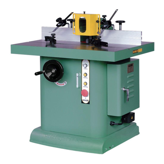
Heavily ribbed, solid cast iron table with a smooth ground
surface finish.
Four(4) spindle speeds with reverse.
Independently adjustable left and right industrial duty
fences with precision fine-tune adjustment dials.
Deluxe precision T-slot miter gauge for better workpiece
control.
5HP industrial motor protected against dust by a totally
enclosed cabinet.
Magnetic switch with thermal overload protection.
Quick release belt tensioning system for quick and easy
speed changes.
Built-in caster system for instant mobility within the shop.
Large cutter guard with window, spring hold down and
built-in 4" dust outlet.
Convenient, extra large adjustment handles.
MOTOR M1
5 HP, 220V, 1 PH 60HZ.25A
WEIGHT
748 IBS (340 Kg)
Advertisement
Table of Contents

Related Manuals for General International 40-350


Summary of Contents for General International 40-350
- Page 1 Heavily ribbed, solid cast iron table with a smooth ground surface finish. Four(4) spindle speeds with reverse. Independently adjustable left and right industrial duty fences with precision fine-tune adjustment dials. Deluxe precision T-slot miter gauge for better workpiece control. 5HP industrial motor protected against dust by a totally enclosed cabinet.
- Page 2 GENERAL ® INTERNATIONAL guarantee All component parts of GENERAL INTERNATIONAL machinery are carefully inspected during all production stages and each machine is thoroughly Inspected upon completion of assembly. Because of quality, GENERAL INTERNATIONAL agrees to within a period of 24 months from date of purchase.ln order to obtain warrantee, all defective parts must be returned prepaid...
- Page 3 1. GUARD 2. FENCE 3. SAFETY GUARD 4. KNOB 5. SCREW KNOB 6. WASHER 7. RETAINER (L) RETAINER (S) 9. PLATE GUARD 10. TENSION 11. WRENCH 12. BAR 13. MITER GAUGE 14. MITER GAUGE FENCE SPINDLE 16. WRENCH WRENCH 18. ADJUSTMENT HANDLE 19.
-
Page 4: Unpacking And Cleanup
inspected before shipment and if properly used will give perfect results, However, a reasonable amount of care and attention is necessary to ensure perfect performance and accurate work. It is imperative that you take a few moments to familiarize yourself with these instructions, as they will no doubt save you a lot of UNPACKING AND CLEANUP and install it accurately before use. -
Page 5: Speed Change And Belt Adjustment
FIG.2 SPEED CHANGE AND BELT ADJUSTMENT FIG.3 Follow these procedures to change speed and adjust the proper belt tension. 1. Disconnect machine from power source. 2. Open guard door. 4.Move the belt to the other groove (Fig. 3B) FIG.4 5. Push handle bar (Fig. 3C) to get proper belt tension 6. -
Page 6: Changing Cutters
FIG.6 CHANGING CUTTERS All spindle sizes are equipped with a safety lock nut, Left- h a n d t h r e a d s are found above the large spindle nut. (Fig.7) To mount change cutter, first remove the safety lock nut. Remove the spindle nut by placing one wrench on the spindle nut and another wrench on the flats on top of the spindle. - Page 7 FIG.10 OPERATING CONTROLS FOR THE FENCE Depending on the type of work you are shaping, either side of the fence can be moved freely. Fence can be moved by loosening wing screws (A),(Fig.11) Proper setting can be achieved by turning knob (B). The turning knob (B) is with scale for accurate setting. Wing screws (A) must be then tightened to fix in position.
-
Page 8: Periodical Maintenance
ROTECTION GUARD ADJUSTMENT (FIG. 15) FIG.15 1. Loosen two knobs (A) to slide protector to desired height. PERIODICAL MAINTENANCE Experienced technician should be contacted when the ball bearings • Spindle must always be cleaned properly and with care, with the use of compressed air jet. -
Page 9: Before Operating
Spacers, cutters and collars mounted on the spindle shaft must be in a fixed position. There must be no movement, space or touching between parts. 2. Counter bores and holes of collars, cutters or spacers must be in perfect condition with no rust or flaws. -
Page 10: Grain Direction
GRAIN DIRECTION The work piece should always be shaped in the same direction as the grain (if possible). When cut against the wood grain, woods as redwood, fir and oak will leave a rough, or slightly splintered edge. CAUTION: When deep cuts are required, they will need strong power and a pushing force in order to control the cut. - Page 11 EDGE SHAPING: SHORT BOARDS When edge shaping short boards, never attempt to hand guide any stock less than 12 inches long, or narrower than 3 inches without the use of a special guide (Fig. 22) END SHAPING When end shaping narrow stock at least one half of the work piece end must be in contact with either the outfeed or infeed fence.
- Page 12 SHAPING CONTOURED EDGES WITH RUB COLLARS To shape contoured edges the fence assembly should be removed. In order to control the work piece and limit the depth of cut an anti-friction collar must be used.(Fig, 26) The purpose of the collar is to ride against the work piece, collar can be positioned above or below the cutters.
- Page 13 ENCLOSED EDGE SHAPING Inside edge work piece are shaped the same way as outside edges (Fig.31). When the whole edge needs to be shaped, the operator must use The work piece must be placed on table before starting the motor. The operator must shape the whole work piece by feeding into the cutters.
-
Page 14: Horizontal Toggle Clamp
SECURING A TEMPLATE TO THE WORK PIECE Various methods are used to secure template to the work piece. The operator should select the best method to secure the template to the work piece based on piece is large enough to surpass the front of table, while still leaving space for the desired cut. -
Page 15: Stacked Cutters
STACKED CUTTERS A variety of timesaving and interesting cuts can be made in a single setup by stacking the cutters (Fig. 39). When stacking cutters extra care should be taken. Check that cutters have no flaw nicks, or just. Cutters must cleaned and perfectly balanced before placing in the stacked poisiton. -
Page 16: Butt Joints
BUTT JOINTS All butt type joints require both work pieces to be perfectly squared and inline and adjusted for a depth of cut (Fig. 45). both cuts on the work pieces are part- edge cuts that do not reduce the width of material during cutting procedures. - Page 17 BASE...
-
Page 18: Parts List
PARTS LIST 40-350 PART N0. DESCRIPTION SPECIFICATION 40350-1 TABLE INSERT 40350-2 TABLE INSERT 40350-3 TABLE INSERT 40350-4 SET SCREW CAP PT 5/16" X 5/8" 40350-5 TABLE 30" X 40" X 85mm 40350-6 WASHER 3/8" 40350-7 SPRING WASHER 3/8" 40350-8 SCREW 3/8"... - Page 19 QUILL PARTS LIST 40-350 PART N0. DESCRIPTION SPECIFICATION 40350-43 SCREW 1/4" X 1" 40350-44 SPRING WASHER 1/4" 40350-45 WASHER 1/4" 40350-46 HAND WHEEL 40350-47 LOCK SHAFT 40350-48 5/16" 40350-49 SCREW 5/16" X 3/4" 40350-50 LOCK SCREW GEAR...
- Page 20 PARTS LIST 40-350 PART N0. DESCRIPTION SPECIFICATION 40350-51 WASHER 40350-52 GEAR 40350-53 SCREW 5/16" X 1" 40350-54 SCREW 5/16" X 1" 40350-55 5/16" 40350-56 SPRING WASHER 5/16" 40350-57 WASHER 5/16" 40350-58 KNOB 40350-59 HAND WHEEL 40350-60 BASE GEAR FOR SHAFT...
- Page 21 FENCE PARTS LIST 40-350 PART N0. DESCRIPTION 40350-104 SCREW 40350-105 HANDLE LOCK 40350-106 WASHER 40350-107 BRACKET ASSY FENCE 40350-108 SCREW(T) 40350-109 BAR(L) 40350-110 COUNTERSUNK SETSCREW...
- Page 22 PARTS LIST 40-350 PART N0. DESCRIPTION SPECIFICATION 40350-111 40350-112 FENCE 40350-113 KNOB 40350-114 SCREW 40350-115 KNOB 40350-116 RETAINER 40350-117 KNOB 40350-118 SHAFT 40350-119 KNOB 40350-120 LOCK KNOB 40350-121 HANDLE LOCK 40350-122 T-HEX NUT 3/8" 40350-123 SPRING TENSION 40350-124 KNOB 40350-125...
- Page 23 SPINDLE PARTS LIST 40-350 PART N0. DESCRIPTION SPECIFICATION 40350-167 LOCK BOLT 40350-168 LOCK NUT 40350-169 BEARING 40350-170 SNAP RING S-30 40350-171 SPINDLE PULLEY 40350-172 LOCK WASHER 40350-173 LOCK NUT 40350-174 BEARING 40350-175 BEARING 40350-176 QUILL 40350-177 SPINDLE 1-1/4" 40350-178 SHAFT...
Need help?
Do you have a question about the 40-350 and is the answer not in the manual?
Questions and answers