Advertisement
Table of Contents
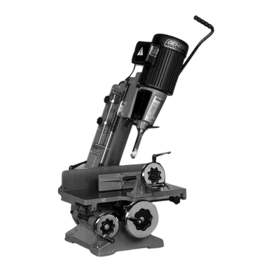
THIS HOLLOW CHISEL MORTISER IS MANUFACTURED AND
DESIGNED FOR SPECIALIZED WOODWORKERS.
• Heavy duty cast-iron construction, machined with precision.
• Head gas cylinder provides smooth performance.
• Control rods for depth and length stop.
• 5/8" and 3/4" sleeves for chisel shank.
• Threaded rod and vive clamp with handwheel.
• Heavy duty rack and gear provides the entire head to lower in
order to feed mortiser accurately into workpiece.
• Handwheels can be used to move cast-iron table in longitu-
dinal and lateral directions.
• Enclose fan cooled motor with starter capacitor and ribbed
body for resistance and long life.
• Switch with dust protection.
FEATURES
CHISEL CAPACITY
MAXIMUM CHISEL STROKE
DISTANCE FROM FENCE TO CENTER CHISEL
DISTANCE FROM Ø CHISEL TO TABLE (CHISEL 1/4")
CHUCK CAPACITY
SIZE OF TABLE
SIZE OF BASE
TABLE MOVEMENT LONGITUDINAL
TABLE MOVEMENT LATERAL
OVERALL HEIGHT
SPINDLE SPEED
MOTOR
WEIGHT
SPECIFICATIONS
1 ⁄
" TO 1" (6 À 26 mm)
4
8" (200 mm)
3" (77 mm)
1 ⁄
3 ⁄
6
" x 10
(158 x 259 mm)
4
16
1 ⁄
" (13 mm)
2
12" x 12" (305 x 305 mm)
12" x 17" (305 x 432 mm)
1 ⁄
14
" (368 mm)
2
3" (77 mm)
38" (966 mm)
1720 RPM
1 HP, 115 V / 230 V, 1Ph
215 LBS (98 kg)
Advertisement
Table of Contents

Related Manuals for General International 75-075


Summary of Contents for General International 75-075
- Page 1 FEATURES SPECIFICATIONS THIS HOLLOW CHISEL MORTISER IS MANUFACTURED AND 1 ⁄ CHISEL CAPACITY ” TO 1” (6 À 26 mm) DESIGNED FOR SPECIALIZED WOODWORKERS. MAXIMUM CHISEL STROKE 8” (200 mm) • Heavy duty cast-iron construction, machined with precision. DISTANCE FROM FENCE TO CENTER CHISEL 3”...
-
Page 2: Ring
GENERAL ® INTERNATIONAL guarantee All component parts of GENERAL INTERNATIONAL machinery are carefully inspected during all production stages and each machine is thoroughly inspected upon completion of assembly. Because of quality, GENERAL INTERNATIONAL agrees to repair or replace any genuine part or parts which, upon examination, proves to be defective in workmanship or material within a period of 24 months from date of purchase.In order to obtain warrantee, all defective parts must be returned... -
Page 3: Gas Spring
If in doubt, contact a qualified electrician before connecting to the power source. The Mortiser 75-075 has been pre-wired at the factory for 115V operations. To avoid shock or fire, replace the power cord if it gets worn out, cut or damaged in any way. Replace immediately before performing work operations. -
Page 4: Chuck
INSTALLATION AND SETUP (4) Holes have been designed at the base of the cast iron to conveniently bolt and fasten your 75-075 Mortiser to a workbench (optional stand item 75-045), or a solid work surface. Place your machine on the worktable; use a marker to indicate the areas where the holes must be drilled. - Page 5 Perform practice cuts before starting work operations, various Fig. 5 work material require different feedings CHISEL SLOT Complete the first mortising cut; carry the workpiece towards ON LEFT the proper direction of the chisel slot to permit chips to unload clearly. Move the workpiece in order for the chisel slot to release chips into the already cut part of the mortise (Fig.5).
-
Page 6: Rack
TABLE ANGLE ADJUSTMENT Fig. 9 Loosen lock knob (A) and (B). (Fig.9) Point the scale (D) to adjust fence (C) to the desired angle 0° - 30°. Tighten lock knob (A) and (B). Fig. 10 HEAD ADJUSTMENT Adjust head when handle (C) can not be set at proper working position (Fig.10). - Page 7 DIAGRAM 35-1 46 A 44-1 17-1 10-1 48-1...
- Page 8 PARTS LIST IMPORTANT: When ordering replacement parts, always give the model number, serial number of the machine and part number. Also a brief description of each item and quantity desired. PIECE # DESCRIPTION SECIFICATIONS 75075 - 01 BASE 75075 - 02 ADJUSTING BAR 75075 - 03 ROD SCREW...
- Page 9 PARTS LIST IMPORTANT: When ordering replacement parts, always give the model number, serial number of the machine and part number. Also a brief description of each item and quantity desired. PIECE # DESCRIPTION SECIFICATIONS 75075 - 50 ADJUSTING SLEEVE 75075 - 51 LOCK KNOB 75075 - 52 LONG STOP PLATE...
- Page 10 75-075 8360, Champ-d’Eau, Montreal (Quebec) Canada H1P 1Y3 Tel.: (514) 326-1161 Fax : (514) 326-5555 www.general.ca IMPORTANT: When ordering replacement parts, always give the model number, serial number of the machine and part number. Also a brief description of each item and quanti...
Need help?
Do you have a question about the 75-075 and is the answer not in the manual?
Questions and answers