Table of Contents
Advertisement
Available languages
Available languages
Quick Links
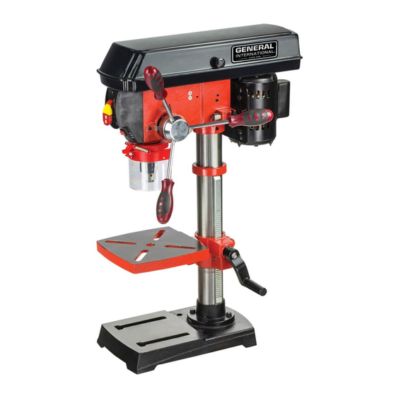
FEATURES
● 5 speeds
● Patented precision cross-
pattern laser alignment and
centering guide
● Unique built-in LED work light
illuminates the work table
● Easy-access safety switch with
removable security key
● Transparent chuck safety guard
● Soft-grip feed handles
● Depth stop with scale
● Heavy cast-iron and steel
construction
SPECIFICATIONS
● Motor: 120 V ~ 60 Hz
● Power: 375 W
● Swing: 10 in. (254 mm)
● Drilling capacity:
1/2 in. (13 mm)
● Taper: JT33
● Quill stroke: 2-3/8 in. (60 mm)
● Speed: 570 - 3050 rpm
● Table tilt: 0 – 45 degrees
● CSA certification
● Net weight:
51 lb. (23 kg)
General International Power Products, LLC
6243 Industrial Parkway
Whitehouse, OH 43571 USA
General International Power Products Ltd.
8360 Champ d'Eau
Montréal, QC H1P1Y3 Canada
website: www.gipowerproducts.com
SETUP & OPERATION MANUAL
10 inch Bench Mount
207013
Model #
DP2002
DP2002 man v.170207
Drill Press
Advertisement
Table of Contents

Related Manuals for General International DP2002


Summary of Contents for General International DP2002
- Page 1 ● CSA certification ● Net weight: 51 lb. (23 kg) 207013 Model # DP2002 General International Power Products, LLC 6243 Industrial Parkway Whitehouse, OH 43571 USA General International Power Products Ltd. 8360 Champ d’Eau Montréal, QC H1P1Y3 Canada website: www.gipowerproducts.com...
-
Page 2: Year Limited Warranty
2-year warranty period, subject to the “conditions and exceptions” as listed below. Repairs made without the written consent of General International will void the warranty. DISCLAIMER The information and specifications in this manual pertain to the unit as it was supplied from the factory at the time of printing. -
Page 3: Important Safety Instructions
Warranty does not include failures, breakage or defects deemed after inspection by General International to have been directly or indirectly ® caused by or resulting from; improper use, or lack of or improper maintenance, misuse or abuse, negligence, accidents, damage in handling or transport, or normal wear and tear of any generally considered consumable parts or components. -
Page 4: Warnings And Cautions
WARNINGS AND CAUTIONS Be sure to read, understand and follow all safety warnings and instructions in the supplied operator’s manual. WORK AREA 1. KEEP CHILDREN AND BYSTANDERS AWAY. All children should be kept away from the work area. Don’t let them handle machines, tools or extension cords. -
Page 5: Tool Safety
10. ALWAYS DISCONNECT TOOL BEFORE SERVICING and when changing accessories such as belts, bits, blades, cutters. 11. KEEP GUARDS IN PLACE and in working order. If a guard must be removed for maintenance or cleaning, make sure it is properly attached before using the tool again. 12. - Page 6 Knowledge is safety. 12. USE ONLY RECOMMENDED ACCESSORIES. Use of accessories NOT recommended by General International may result in a risk of injury. SERVICE 1. INSPECT AND MAINTAIN THE TOOL REGULARLY.
- Page 7 ASSEMBLED and installed according to the instructions. A machine incorrectly assembled can cause serious injury. NOTE: If any parts are damaged or missing, do not attempt to plug in the power cord and turn the switch on until the damaged or missing parts are obtained and are installed correctly.
- Page 8 with the workpiece contacting the bit. Workpiece may be thrown and cause injury or damage. 18. PREVENT THE WORKPIECE from contacting the bit before starting the tool. Loss of control of the workpiece is dangerous. 19. NEVER TURN THE MACHINE ON before clearing the table/work area of all objects (tools, scraps of wood, etc.).
-
Page 9: Electrical Warnings And Cautions
SPEED SETTING OF THE DRILL PRESS. This drill press has 5 spindle speeds. Check spindle speed setting of the drill press based on pulley speed chart located inside the pulley housing. Ensure accessories used have a higher speed rating than the current spindle speed setting of the drill press. -
Page 10: Grounding Instructions
voltage than needed can result in serious injury to the user as well as damage to the machine. If in doubt, contact a qualified electrician before connecting to the power source. 2. MAKE SURE YOUR FINGERS do not contact the terminals of the power cord plug when plugging in or unplugging the saw. -
Page 11: Laser Safety
factors that cannot be built into this product, but must be supplied by the operator. LASER SAFETY This tool is equipped with a patented precision cross-pattern laser alignment and centering guide. 1. DO NOT STARE DIRECTLY AT THE LASER BEAM. DANGER! Eye damage may occur if you deliberately stare into the beam. -
Page 12: Functional Description
FUNCTIONAL DESCRIPTION GETTING TO KNOW YOUR DRILL PRESS WARNING! To avoid injury from accidental start, turn the switch off and remove the plug from the power source outlet before making any adjustments. Item Description Head assembly Table support lock handle Column Base Table bevel lock bolt... -
Page 13: Head Assembly
base with the wrench. MOUNTING ● Drill presses are by their design, quite top-heavy and must be securely fastened in place. ● Fasten your drill press through the mounting holes in the base to a stand or work bench with heavy duty bolts, washers, and nuts. This will prevent it from tipping over, sliding, or walking during operation. - Page 14 SPEED AND BELT TENSION ADJUSTMENT 1. Open the belt & pulley cover (X, fig 2 & 3) DP2002 belt spindle label 2. Consult the belt position / speed diagram. 100 x 40 mm R=2 rpm: 570 tr/min...
- Page 15 3. Loosen the belt tension lock knobs; one on each side of the drill press head. 4. Pull the motor forward, closer to the drill press head. 5. Choose the best speed for the drilling operation planned and install the belt in the correct position on the pulleys to produce that speed.
-
Page 16: Depth Gauge
DEPTH GAUGE 1. To stop the drill's downward travel at a consistent specific depth, particularly for repeat drilling, loosen the depth scale lock (ff, fig 7) located on the depth scale ring (gg, fig 7). 2. Rotate this ring until the pointer (hh, fig 7) is aligned to the desired depth on the scale. -
Page 17: Work Light
● Using a hex wrench, turn the laser adjustment hex screws (3) counterclockwise. ● Move the laser light housing until the two lines intersect where the drill meets the work piece. DO NOT stare directly at the laser lines. ● Re-tighten the adjustment hex screws . WORK LIGHT You may want to light up the work table and eliminate shadows on the work piece. -
Page 18: Maintenance
MAINTENANCE WARNING! For your own safety, turn the switch off and remove the plug from the power source outlet before adjusting, maintaining or lubricating your drill press. WARNING! To avoid electrocution or fire, any repairs to electrical systems should be done by an authorized repair center. GENERAL Keep your tool in good condition by adopting a regular maintenance program. -
Page 19: Quill Return Spring
SPINDLE PLAY 1. Move the spindle to the lowest position and hold it in place with one hand on a feed handle. 2. With your other hand, try to make it revolve around its axis with a side motion. 3. If you find there is too much play: •... -
Page 20: Parts List
PARTS LIST POS. PART NO. DESCRIPTION QTY. POS. PART NO. DESCRIPTION QTY. 13201001A Base 13105009 Circle, rubber 13201002B 20105012 Support, column Bushing, rubber GB21-76 GB6170-86 Hex. hd. screw M8 x 20 Nut, hex. M5 13201003 Column tube 13208001A Battery box 13201010 Rack GB818-85... -
Page 21: Schematic Drawing
SCHEMATIC DRAWING 170207... -
Page 23: Caractéristiques
● Certification CSA ● Poids net : 207013 51 lb (23 kg) Modèle # DP2002 General International Power Products, LLC 6243 Industrial Parkway Whitehouse, OH 43571 USA General International Power Products Ltd. 8360 Champ d’Eau Montréal, QC H1P1Y3 Canada site Web : www.gipowerproducts.com... - Page 24 NOUS VOUS REMERCIONS d’avoir choisi une machine de General International. Cette outil a été soigneusement testée et inspectée avant de vous être expédiée, et moyennant une utilisation et un entretien adéquats, elle vous procurera un service fiable pendant de nombreuses années. Afin d’obtenir un rendement optimal et une utilisation sans problème, et d’optimiser...
- Page 25 de réclamation de garantie peut vous être fourni sur demande par General International ou par un distributeur agréé) spécifiant clairement le ® modèle et le numéro de série de l’unité (si applicable), et faisant état de la plainte ou du défaut présumé, doivent être jointes au produit retourné. CONDITIONS ET EXCEPTIONS Cette couverture ne s’applique qu’au premier acheteur.
-
Page 26: Avertissements Et Précautions
AVERTISSEMENTS ET PRÉCAUTIONS Assurez-vous de lire, comprendre et suivre tous les avertissements et consignes de sécurité dans le manuel de l'opérateur. ZONE DE TRAVAIL 1. TENEZ LES ENFANTS ET AUTRES PERSONNES ÉLOIGNÉS Tous les enfants doivent être tenus à l'écart de la zone de travail. Ne les laissez pas utiliser des machines, des outils ou des rallonges électrique. - Page 27 9. ATTENTION AUX DÉCHARGES ÉLECTRIQUES Éviter tout contact corporel avec des surfaces en mises à la terre. Par exemple: tuyaux, radiateurs, cuisinières, réfrigérateurs. Quand votre corps est en mis à la terre le risque de choc électrique augmente. Lorsque l'on travaille, il est possible d’avoir certains fils électriques avec courant autour de vous, tenter de déterminer si il y a un danger de choc.
- Page 28 changement des accessoires. Gardez les poignées sèches, propres et exempt d'huile et de graisse. 6. DÉBRANCHEZ LE CORDON D’ALIMENTATION AVANT DE PROCÉDER AUX REGLAGES. Changement de pièces et accessoires peut être dangereux si l'outil démarrait accidentellement. 7. ÉVITEZ TOUT DÉMARRAGE INVOLONTAIRE. Assurez-vous que le commutateur est en position ARRÈT/OFF avant de brancher.
- Page 29 cette dernière. Faites preuve de bon sens et gardez toujours à l’esprit les mesures de sécurité qui s’appliquent à la situation particulière de votre atelier. En cas de doutes concernant la sécurité d’une opération que vous êtes sur le point d’effectuer, ARRÊTEZ! N’entamez pas le travail avant d’avoir vérifié...
- Page 30 12. AVANT DE COMMENCER, être certain que le moteur, la table, des pièces jointes et les boutons de réglage sont sécurisés. 13. VÉRIVIEZ SI IL Y A DES PIÈCES ENDOMMAGÉES. Avant d'utiliser cet outil, toutes pièces qui sont endommagées devraient être soigneusement vérifiée pour qu'elle fonctionne bien et effectue sa fonction prévue.
- Page 31 28. UTILISATION DES VITESSES RECOMMANDER pour une opération spécifique ou pour une pièce de matériel spécifique - vérifiez l'étiquette à l'intérieur du couvercle de poulie pour les informations de forage 29. GARDER LE COUVERCLE DES POULIES FERMÉ après les ajustements de courroie terminée 30.
-
Page 32: Instructions De Mise À La Terre
! AVERTISSEMENT ! PROPOSITION 65 DE CALIFORNIE Ce produit ou son cordon d’alimentation peuvent contenir des produits chimiques, dont du plomb, reconnu par l’état de Californie pour provoquer des cancers et des malformations congénitales ou d’autres problèmes de reproduction. Se laver les mains après manipulation. Certaines poussières créées par l’utilisation d’outils électriques tels que sableuse, scie, meule et autre activité... -
Page 33: Rallonges Électriques
RALLONGES ÉLECTRIQUES N’utilisez que des rallonges à trois fils munies de fiches de type mise à la terre triphasées et de prises à trois trous. Remplacez une rallonge endommagée immédiatement. Si vous devez utiliser une rallonge, assurez vous que le calibre du cordon est adapté... -
Page 34: Description Fonctionnelle
Tête Support de la table avec poignée de blocage Colonne Base Batteries AA (2) 4 x boulons hex. Poignée de manivelle Table Arbre de vis sans fin Garde du mandrin Mandrin 1/2 po Clé du mandrin Poignées d’alimentation (3 pc.) 2 clés hex (3 mm &... -
Page 35: Procédure D'assemblage
PROCÉDURE D’ASSEMBLAGE ATTENTION! Pour votre propre sécurité, ne jamais débrancher la prise à la source ou insérer la clé de l'interrupteur jusqu'à ce que toutes les étapes de montage sont complétés et que vous ayez lu et compris le manuel du propriétaire. OUTILS REQUIS ●... - Page 36 9. Faites glisser la manivelle du support de table (G, fig 2 et 3) sur l'arbre de vis sans fin saillant à partir du côté du support de table. Fixez-le avec l'ensemble avec la vis à tête creuse en veillant à ce que la vis de réglage soit aligné...
- Page 37 AJUSTEMENT DE LA VITESSE ET DE LA TENSION DES COURROIES 1. Ouvrez-le couvercle de poulie (X, fig 2 et 3) DP2002 belt spindle label 2. Consultez le diagramme position de la courroie / vitesse. 100 x 40 mm R=2 3. Desserrez les boutons de verrouillage de tension de la courroie; de...
-
Page 38: Instructions D'opération
4. Resserrer la table. REMARQUE : Il serait une bonne idée de toujours vérifier si l'angle est correct avec un équerre combiné. La table doit être à l’équerre pour des opérations de forage normales. 1. Utilisez l'échelle de biseau sur le support d'une jauge et mettre la table à... -
Page 39: Lampe De Travail
MÈCHE ET FORET 1. Insérez le foret dans le mandrin (K, fig 3) assez loin pour obtenir adhérence maximale des mâchoires du mandrin. Assurez-vous que la mèche est centrée dans le mandrin. 2. Insérez la clé de mandrin (L, fig 2) et la tourner dans le sens horaire pour serrer (et dans le sens antihoraire pour desserrer) le foret. -
Page 40: Entretien
ENTRETIEN ATTENTION! Pour votre propre sécurité, éteindre l'interrupteur et retirez le cordon de la source d'alimentation avant de régler, d'entretenir ou lubrifier votre perceuse. ATTENTION! Pour éviter les chocs ou le potentiel d’incendie, toute réparation électrique devrait être effectuées par un centre de réparation agréé. - Page 41 JEU DE L’AXE 1. Placez l’axe à la position la plus basse et le maintenir en place avec un la main sur une poignée d'alimentation. 2. Avec votre autre main, essayer de le faire tourner autour de son axe avec un mouvement de côté. 3.
-
Page 42: Liste De Pièces
LISTE DE PIÈCES POS. DESCRIPTION QTÉ. POS. DESCRIPTION QTÉ. PIÈCE PIÈCE 13201001A 20105012 Base Bague de caoutchouc 13201002B Support de colonne GB6170-86 Écrou hex. M5 GB21-76 13208001A Vis hex. M8 x 20 Boîtier de batterie 13201003 GB818-85 Colonne Vis à tête cylindrique bombée M4 x 10 13201010 Crémaillère... - Page 43 SCHÉMA 170207...
Need help?
Do you have a question about the DP2002 and is the answer not in the manual?
Questions and answers