Advertisement
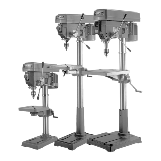
Rotating, 45° tilting, crank-operated work-
table with quick release clamp.
Large front mounted stop switch with
lock-out safety feature to prevent unwan-
ted or unintentional start-up.
Adjustable spindle tension return spring.
Built-in lamp illuminates the drilling area.
(bulb not included)
Cast iron pulleys reduce vibration.
Industrial 3/4 HP motor. - #75-100/200
Industrial 1 HP motor. - #75-500
Heavy-duty positive depth stop for quick
adjustment.
SWING
17'' (432 mm)
- #75-100/200
22'' (559 mm)
- #75-500
DRILLING CAPACITY
3 ⁄
" (19 mm)
- #75-100/200
4
1
" (32 mm)
1 ⁄
- #75-500
4
CHUCK SIZE
5 ⁄
" (16 mm)
- #75-100/200
8
3 ⁄
" (19 mm)
- #75-500
4
SPINDLE TRAVEL
3
1 ⁄
" (82.5 mm)
- #75-100/200
4
4
1 ⁄
" (114 mm)
- #75-500
2
SPINDLE DISTANCE TO TABLE
18" (460 mm)
- #75-100
27
7 ⁄
" (706 mm)
- #75-200
8
25
3 8
" (644 mm)
- #75-500
SPINDLE DISTANCE TO BASE
26" (660 mm)
- #75-100
48" (1220 mm)
- #75-200
46
3 ⁄
" (1188 mm)
- #75-500
4
TABLE SIZE
12" x 12" (305 x 305 mm)
- #75-100/200
18
" x 16
" (470 x 410 mm)
1 ⁄
1 ⁄
2
8
SPINDLE SPEEDS (12)
340-2800 RPM
- #75-100/200
120-2270 RPM
- #75-500
SPINDLE TAPER
MT 2
- #75-100/200
MT 4
- #75-500
OVERALL HEIGHT
41
3 ⁄
" (1061 mm)
- #75-100
4
64
1 ⁄
" (1638 mm)
- #75-200
2
68
3 ⁄
" (1747 mm)
- #75-500
4
BASE SIZE
11
3 ⁄
" x 19
5 ⁄
" (302 x 500 mm)
4
8
11
3 ⁄
" x 19
5 ⁄
" (302 x 500 mm)
4
8
22
1 ⁄
" x 19
1 ⁄
" (572 x 496 mm)
2
2
MOTOR
HP , 110 V, 1 Ph, 12 A
3 ⁄
- #75-100/200
4
1 HP , 110/220 V, 1 Ph, 14/7 A
WEIGHT
169 LBS (77 kg)
- #75-100
200 LBS (91 kg)
- #75-200
372 LBS (169 kg)
- #75-500
- #75-500
- #75-100
- #75-200
- #75-500
- #75-500
REVISION 4 - NOVEMBER 25/10
© Copyright General® International 11/2010
Advertisement
Table of Contents

Related Manuals for General International 75-100


Summary of Contents for General International 75-100
- Page 1 Adjustable spindle tension return spring. Built-in lamp illuminates the drilling area. (bulb not included) Cast iron pulleys reduce vibration. Industrial 3/4 HP motor. - #75-100/200 Industrial 1 HP motor. - #75-500 Heavy-duty positive depth stop for quick adjustment. SWING 17’’...
- Page 2 THANK YOU for choosing this General ® International model 75-100/75-200/ 75-500 drill press. This drill has been carefully tested and inspected before shipment and if properly used and maintained, will provide you with years of reliable service. To ensure opti- mum performance and trouble-free operation, and to get the most from your investment, please take the time to read this manual before assembling, installing and operating the unit.
- Page 3 ® ® GENERAL & GENERAL INTERNATIONAL WARRANTY All component parts of General®, General® International and Excalibur by General International ® products are carefully inspected during all stages of production and each unit is thoroughly inspected upon completion of assembly. Limited Lifetime Warranty Because of our commitment to quality and customer satisfaction, General®...
-
Page 4: Rules For Safe Operation
RULES FOR SAFE OPERATION To help ensure safe operation, please take a moment to learn the machine’s applications and limitations, as well as poten- tial hazards. General® International disclaims any real or implied warranty and holds itself harmless for any injury that may result from improper use of its equipment. -
Page 5: Electrical Requirements
We suggest you ask your local General International distributor to recommend qualified electricians in your area (or perhaps one of their own technicians) who can make this conversion properly and safely. -
Page 6: Assembly Instructions
Attach the head (2) to the column and tighten the head with the set screws (3). Secure the table onto the table arm. (75-100/200 ONLY) Attach the 3 feed handles, (4, 5 & 6), to the handle body (7). -
Page 7: Adjustments And Controls
Note: It may be necessary to rotate the quill in order to be able to get the tool all the way through. While holding onto the chuck to prevent damage, raise the quill assembly. The arbor and chuck should fall out. ADJUSTMENTS AND CONTROLS 75-100/200 75-500 POWER “ON”... - Page 8 TABLE SWING ADJUSTMENT TABLE ROTATION ADJUSTMENT ADJUSTING TABLE HEIGHT Loosen column lock handle (1). Loosen the column lock (75-100/200 Only) handle (1). Swing the table arm bracket and Loosen the table lock handle (3). the table to the desired position.
-
Page 9: Maintenance
Bearings in the quill and the V-belt pulley are sealed, permanently lubricated and maintenance free. • Lightly oil the slide bars every 2 months. • If cranking becomes difficult, grease the column bracket. IMPORTANT: USE ONLY GENERAL INTERNATIONAL OR AUTHORIZED REPLACEMENT PARTS AND ACCESSORIES. -
Page 10: Recommended Optional Accessories
RECOMMENDED OPTIONAL ACCESSORIES We offer a large variety of products to help you increase convenience, productivity, accuracy and safety when using your drill press Here’s a small sampling of optional accessories available from your local General International dealer. For more information about our products, please visit our website at www.general.ca 25 PIECE - RUBBER MORTISING ATTACHMENT KIT ABRASIVE SLEEVES... -
Page 11: Parts List
PARTS LIST 75-100 & 75-200 PART N0. DESCRIPTION 75200-01 GUARD COVER 75200-02 PAN HEAD SCREW 75200-04 75200-05 SPINDLE PULLEY V-BELT 75200-06 75200-07 MIDDLE PULLEY 75200-08 BALL BEARING 75200-09 RETAINING RING 75200-10 MOTOR PULLEY 75200-11 V-BELT SET SCREW 75200-12 SCREW 75200-13... - Page 12 PARTS LIST – 75-100 & 75-200 PART N0. DESCRIPTION 75200-54 75200-55 RUBBER 75200-56 JUNCTION BOX 75200-57 SCREW 75200-58 RETAINING RING 75200-59 BALL BEARING 75200-60 RUBBER WASHER 75200-61 QUILL 75200-62 THRUST BEARING 75200-63 SCREW 75200-64 CLAMPING SEAT DEPTH STOP 75200-65 LOCK NUT...
- Page 13 DIAGRAM 75-100 & 75-200 13-1 25-1 92 B...
-
Page 14: On/Off Switch
PARTS LIST 75-500 PART N0. DESCRIPTION 70500-01 SPINDLE PULLEY 70500-02 70500-03 PULLEY COVER 70500-04 SCREW 70500-06 BEARING 70500-07 V-BELT 70500-08 MIDDLE PULLEY 70500-09 RETAINING RING 70500-10 V-BELT 70500-11 RETAINING RING 70500-12 SHAFT ASSEMBLY 70500-13 MOTOR PULLEY 70500-14 SCREW 70500-15 STRAIN RELIEF 70500-16 MOTOR CORD 70500-17... - Page 15 PARTS LIST 75-500 PART N0. DESCRIPTION 70500-60 SET SCREW 70500-61 PAN SCREW 70500-62 LAMP BRACKET 70500-63 SPACER 70500-64 PINION SHAFT 70500-65 FEED HANDLE 70500-66 KNOB 70500-67 SPINDLE NUT 70500-68 BEARING 70500-69 QUILL BASKET 70500-70 QUILL 70500-71 THRUST BEARING 70500-72 BEARING 70500-73 SPINDLE 70500-74...
- Page 16 DIAGRAM 75-500 76-1...
- Page 17 NOTES:...
- Page 18 75-100/75-200/75-500 8360 Champ-d’Eau, Montreal (Quebec) Canada H1P 1Y3 Tel.: (514) 326-1161 Fax: (514) 326-5565 - Fax: (514) 326-5555 - Parts & Service / Order Desk orderdesk@general.ca www.general.ca IMPORTANT When ordering replacement parts, always give the model number, serial number of the machine and...
Need help?
Do you have a question about the 75-100 and is the answer not in the manual?
Questions and answers