Allied Telesis 2914 Series Installation And User Manual
Fiber network adapters with wake on lan (wol)
Hide thumbs
Also See for 2914 Series:
- Installation and user manual (114 pages) ,
- Installation and user manual (108 pages)

Subscribe to Our Youtube Channel
Related Manuals for Allied Telesis 2914 Series


Summary of Contents for Allied Telesis 2914 Series
- Page 1 2914 Series Fiber Network Adapters with Wake on LAN (WoL) AT-2914SX/SC AT-2914SX/LC AT-2914SP Installation and User’s Guide 613-002358 Rev. A...
- Page 2 Telesis, Inc. be liable for any incidental, special, indirect, or consequential damages whatsoever, including but not limited to lost profits, arising out of or related to this manual or the information contained herein, even if Allied Telesis, Inc. has been...
- Page 3 This product meets the following standards: Federal Communications Commission Interference Statement Declaration of Conformity Manufacturer Name: Allied Telesis, Inc. Declares that the product: Fiber Network Adapter with WoL Model Number: AT-2914SX/SC, AT-2914SX/LC, AT-2914SP This device complies with Part 15 of the FCC Rules. Operation is subject to the following two conditions: (1) This device may not cause harmful interference, and (2) this device must accept any interference received, including interference that may cause undesired operation.
- Page 4 European Union Restriction of the Use of Certain Hazardous Substances (RoHS) in Electrical and Electronic Equipment This Allied Telesis RoHS-compliant product conforms to the European Union Restriction of the Use of Certain Hazardous Substances (RoHS) in Electrical and Electronic Equipment. Allied Telesis ensures RoHS conformance by requiring supplier Declarations of Conformity, monitoring incoming materials, and maintaining manufacturing process controls.
- Page 5 FCC Class B Safety UL1950 CSA22.2 No.950 Translated Safety Statements Important: The indicates that a translation of the safety statement is available in a PDF document titled “Translated Safety Statements” on the Allied Telesis website at www.alliedtelesis.com/ support.
-
Page 7: Table Of Contents
Contents Preface ....................................9 Safety Symbols Used in this Document..........................10 Contacting Allied Telesis ..............................11 Chapter 1: Introduction ..............................13 Description....................................14 2914 Series Network Adapter Models ...........................15 SC Optical Fiber Connector............................15 LC Fiber Optic Adapter..............................15 SFP Slot ..................................15 LED ....................................16 Model Naming Conventions..............................17 Supported Operating Systems .............................18... - Page 8 2914 Series Fiber Network Adapters with WoL Installation and User’s Guide Interrupt Moderation ................................57 Jumbo Mtu ....................................58 Large Send Offload v2 (IPv4) ...............................59 Large Send Offload v2 (IPv6) ...............................61 Maximum Number of RSS Queues............................62 Network Address...................................64 NS Offload ....................................66 Priority & VLAN ..................................67 Receive Side Scaling ................................69...
-
Page 9: Preface
Preface This manual is the installation and user’s guide for the 2914 Series Fiber Network Adapters with WoL. The network adapters included in this series are: AT-2914SX/SC AT-2914SX/LC AT-2914SP The Preface contains the following sections: “Safety Symbols Used in this Document” on page 10 ... -
Page 10: Safety Symbols Used In This Document
2914 Series Fiber Network Adapters with WoL Installation and User’s Guide Safety Symbols Used in this Document This document uses the following conventions: Note Notes provide additional information. Caution Cautions inform you that performing or omitting a specific action may result in equipment damage or loss of data. -
Page 11: Contacting Allied Telesis
Preface Contacting Allied Telesis If you need assistance with this product, you may contact Allied Telesis technical support by going to the Support & Services section of the Allied Telesis web site at www.alliedtelesis.com/support. You can find links for the following services on this page: 24/7 Online Support - Enter our interactive support ... - Page 12 2914 Series Fiber Network Adapters with WoL Installation and User’s Guide...
-
Page 13: Chapter 1: Introduction
Chapter 1 Introduction This chapter provides an introduction to the 2914 Series Fiber Network Adapters with WoL. This chapter contains the following sections: “Description” on page 14 “Model Naming Conventions” on page 17 “Supported Operating Systems” on page 18 ... -
Page 14: Description
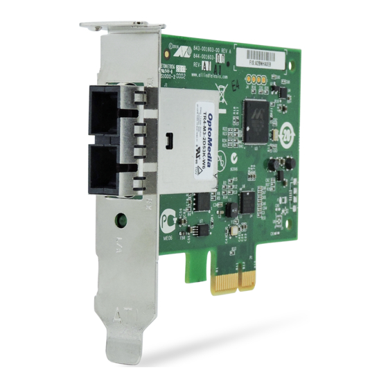
2914 Series Fiber Network Adapters with WoL Installation and User’s Guide Description The 2914 series fiber network adapters are 100/1000Mb Ethernet PCI Express (PCIe) cards developed based on a Marvell 88E6320 switch chip and Broadcom’s BCM57762 network controller. The 2914 series network adapter is equipped with one fiber optic port or SFP slot and supports the Wak-on-LAN (WoL) feature. -
Page 15: 2914 Series Network Adapter Models
Chapter 1: Introduction 2914 Series The AT-2914 series includes the following models: Network Adapter AT-2914SX/SC Models AT-2914SX/LC AT-2914SP SC Optical Fiber The AT-2914SX/SC network adapter is equipped with a 1000BASE-SX port with the SC connector. Connector The SC connector is shown in Figure 2. -
Page 16: Led
The SFP slot is shown in Figure 4. Figure 4. SFP Slot The 2914 series network adapters come with one LED as shown in Figure 5. The LED indicates the link and activity status of the port. Figure 5. LED’s on the Copper Port Table 1 describes the link states that the LED indicates. -
Page 17: Model Naming Conventions
Chapter 1: Introduction Model Naming Conventions The hardware features of the 2914 series network adapters are represented by the letters and numbers in the model names. The conventions for the 2914 series network adapters are identified in Figure 6. Figure 6. 2914 Series Model Naming Conventions The conventions are defined in Table 2. -
Page 18: Supported Operating Systems
Linux 2.6 The 2914 series network adapter that is installed on Linux systems uses Linux inbox driver software to operate so that you do not need to install driver software for Linux systems. A driver supplied with an operating system is called an inbox driver. -
Page 19: Accessing Documents
Chapter 1: Introduction Accessing Documents Documents for the 2914 series network adapters are available at Allied Telesis websites. Allied Telesis To access documents for 2914 series network adapters, do the following: Documents 1. Open a web browser, such as Internet Explorer or FireFox, on your system and enter the following: http://www.alliedtelesis.com/... -
Page 20: Contents Of Your Shipment
2914 Series Fiber Network Adapters with WoL Installation and User’s Guide Contents of Your Shipment The following items are Included with your network adapter: Antistatic bag The network adapter is shipped in an antistatic bag. It protects the network adapter when stored or shipped. Keep the network adapter in its packaging until ready for installation. -
Page 21: Warranty Registration
Warranty Registration Allied Telesis hardware products are covered under limited warranties. All Allied Telesis warranties are subject to and provided only on the terms and conditions set out in the Allied Telesis Limited Warranties listed on the Allied Telesis website at http://alliedtelesis.com/support/warranty. - Page 22 2914 Series Fiber Network Adapters with WoL Installation and User’s Guide...
-
Page 23: Chapter 2: Installing The Hardware
Chapter 2 Installing the Hardware This chapter contains the following sections: “System Requirements” on page 24 “Reviewing Safety Precautions” on page 25 “Pre-Installation Checklist” on page 27 “Replacing the Bracket” on page 28 “Installing a Network Adapter” on page 30 ... -
Page 24: System Requirements
2914 Series Fiber Network Adapters with WoL Installation and User’s Guide System Requirements Before installing the 2914 series network adapter, make sure your system meets the requirements listed below: PC with one of the following operating systems installed: –... -
Page 25: Reviewing Safety Precautions
Note indicates that a translation of the safety statement is available in a PDF document titled “Translated Safety Statements” posted on the Allied Telesis website at www.alliedtelesis.com/ support/software/. Warning Do not stare into the laser beam. ... - Page 26 2914 Series Fiber Network Adapters with WoL Installation and User’s Guide Warning The module is being installed in a system that operates with voltages that can be lethal. Before you remove the cover of your system, you must observe the following precautions to protect yourself and to prevent damage to the system components.
-
Page 27: Pre-Installation Checklist
Chapter 2: Installing the Hardware Pre-Installation Checklist Before installing the 2914 series network adapter, check the following list: 1. Check that your computer has an appropriate open PCIe slot. 2. Check that the power supply on your computer has a SATA power connector. -
Page 28: Replacing The Bracket
2914 Series Fiber Network Adapters with WoL Installation and User’s Guide Replacing the Bracket The 2914 series network adapter is shipped with the low-profile bracket attached to the adapter. Depending on your system, you may need to replace the bracket attached to your adapter card. - Page 29 Chapter 2: Installing the Hardware Figure 8. Fastening Screws onto Standard Bracket...
-
Page 30: Installing A Network Adapter
2914 Series Fiber Network Adapters with WoL Installation and User’s Guide Installing a Network Adapter The following instructions apply to installing a 2914 series network adapter in most systems. Refer to the manuals that were supplied with your system for details about performing these tasks on your particular system. - Page 31 Chapter 2: Installing the Hardware Figure 9. Removing the PC Cover 3. Select an empty, non-shared PCIe slot and remove the faceplate. Keep the faceplate in a safe place. You may need it for future use. See Figure 10. Figure 10. Removing the Faceplate From PCIe Slot Note If you cannot locate or know how to find a PCIe slot, refer to the documentation that came with your system.
- Page 32 2914 Series Fiber Network Adapters with WoL Installation and User’s Guide Warning The module is being installed in a system that operates with voltages that can be lethal. Before you remove the cover of your system, you must observe the following precautions to protect yourself and to prevent damage to the system components.
- Page 33 Chapter 2: Installing the Hardware 6. Secure the network adapter to the chassis with a Phillips-head screw (not provided) as shown in Figure 12. Figure 12. Securing the Network Adapter 7. Replace the system’s cover and secure it with the screws removed in step 2.
-
Page 34: Connecting The Network Cables
2914 Series Fiber Network Adapters with WoL Installation and User’s Guide Connecting the Network Cables The 2914 series network adapter is equipped with the fiber optic port. To connect the network adapter to the network, you must have a fiber optic cable with the appropriate connector. - Page 35 Chapter 2: Installing the Hardware After the system is connected to the network and power is supplied, the network adapter attempts to establish the connection as follow: With a Gigabit SFP, the network adapter attempts to negotiate duplex and flow control via the auto-negotiation protocol. If the link partner does not support Auto-negotiation, the network adapter bypasses the process and attempts to establish a link at 1000Mpbs in full duplex.
- Page 36 2914 Series Fiber Network Adapters with WoL Installation and User’s Guide...
-
Page 37: Chapter 3: Installing The Driver Software
Chapter 3 Installing the Driver Software This chapter describes how to install driver software for the 2914 series network adapter onto your operating system. It contains the following topics: “Overview” on page 38 “Downloading the Driver Software” on page 39 ... -
Page 38: Overview
2914 Series Fiber Network Adapters with WoL Installation and User’s Guide Overview When you install the 2914 series network adapter on your computer, your next step is to install driver software onto your Windows operating system. You can install driver software using Device Manager or using the silent installation method. -
Page 39: Downloading The Driver Software
Chapter 3: Installing the Driver Software Downloading the Driver Software The 2914 series network adapter is not shipped with a software driver CD. You must download driver software from the Allied Telesis website. To download driver software, do the following: 1. - Page 40 2914 Series Fiber Network Adapters with WoL Installation and User’s Guide A window as shown in Figure 14 pops up and prompts you to specify the location of a folder that you want to place unzipped files in. Figure 14. Specifying the Folder for Unzipped Files 5.
-
Page 41: Accessing Device Manager
Chapter 3: Installing the Driver Software Accessing Device Manager When you install or update the driver software for 2914 series network adapter, you must first access Device Manager. The procedures for accessing Device Manager are slightly different among Windows operating systems. To access Device Manager on your... -
Page 42: Installing The Driver Software
2914 Series Fiber Network Adapters with WoL Installation and User’s Guide Installing the Driver Software Once you physically install the 2914 series network card, the system detects the new hardware and creates an entry in Device Manager when the Windows operating system first boots up. Shortly after you log in, you need to install the driver software for your adapter card. - Page 43 Chapter 3: Installing the Driver Software 4. Select Update Driver Software. The Update Driver Software window pops up. See Figure 17 on page 43 as an example. Figure 17. Update Driver Software Window 5. Select Browse my computer for driver software. The Update Driver Software window prompts you to enter the location of the driver folder.
- Page 44 2914 Series Fiber Network Adapters with WoL Installation and User’s Guide Figure 18. Update Driver Software Window 6. Specify the location of the driver software. See “Downloading the Driver Software” on page 39 for details. 7. Click Next. The confirmation message shown in Figure 19 on page 44 appears when the driver software is successfully updated.
-
Page 45: Updating The Driver Software
If your operating system automatically installs a default driver or Broadcom driver, you need to update the driver software with the driver that you downloaded from the Allied Telesis website. To obtain the latest version of the AT-2914 network adapter driver, see “Downloading the Driver Software”... -
Page 46: Performing The Silent Installation
2914 Series Fiber Network Adapters with WoL Installation and User’s Guide Performing the Silent Installation To simplify the driver installation process, you may perform a silent installation when installing driver software for the AT-2914 network adapter card entries. The silent installation is a method of installing software in the silent mode without constant interactions by suppressing dialog boxes. -
Page 47: Viewing Supported Dpinst Options
Chapter 3: Installing the Driver Software 7. Change the directory to the folder where the dpinst utility and the driver files reside. 8. Install the driver in the silent mode by entering the following command: > dpinst /S Note Adding the /S switch to the dpinst command suppresses the display of wizard pages, user dialog boxes, and other user intervention requests. - Page 48 2914 Series Fiber Network Adapters with WoL Installation and User’s Guide...
-
Page 49: Chapter 4: Modifying Advanced Properties
Chapter 4 Modifying Advanced Properties This chapter includes the following topics: “Overview” on page 50 “Accessing Advanced Properties” on page 51 “802.3az EEE” on page 52 “ARP Offload” on page 53 “Ethernet@WireSpeed” on page 54 “Flow Control”... -
Page 50: Overview
2914 Series Fiber Network Adapters with WoL Installation and User’s Guide Overview The 2914 series network adapters allow you to modify advanced properties to meet your requirements. To access the advanced properties, access Device Manager, then go to each advanced property page. -
Page 51: Accessing Advanced Properties
1. Access Device Manager. See “Accessing Device Manager” on page 41. 2. In the Device Manager window, double-click Allied Telesis AT-2914 Series Fiber Ethernet. The properties window pops up. 3. Click the Advanced tab. -
Page 52: Az Eee
2914 Series Fiber Network Adapters with WoL Installation and User’s Guide 802.3az EEE The 802.3az EEE (Energy Efficient Ethernet) property allows you to optimize the energy usage of the interface over Ethernet. Note This feature is valid only for copper ports. Because the port of the 2914 series network adapter is a fiber connector, the setting is always disabled. -
Page 53: Arp Offload
Chapter 4: Modifying Advanced Properties ARP Offload The ARP Offload feature enables the adapter not to wake up when responding to an ARP request. ARP is used to verify whether a computer is still present on the network and resolute an IP address into a MAC address. -
Page 54: Ethernet@Wirespeed
2914 Series Fiber Network Adapters with WoL Installation and User’s Guide Ethernet@WireSpeed The Ethernet@WireSpeed feature connects two devices even when the devices are connected through an impaired copper cable. Note This feature is valid only for copper ports. Because the port of the 2914 series network adapter is a fiber connector, the setting is always disabled. -
Page 55: Flow Control
Chapter 4: Modifying Advanced Properties Flow Control The Flow Control feature allows you to control the flow between the AT-2914 adapter port and its link partner. You can enable or disable the adapter port to process received PAUSE frames and transmit PAUSE frames. - Page 56 2914 Series Fiber Network Adapters with WoL Installation and User’s Guide Tx & Rx Enabled — The adapter processes PAUSE frames when receiving and transmits PAUSE frames. Rx Enabled — The adapter processes PAUSE frames when receiving, but does not transmit PAUSE frame.
-
Page 57: Interrupt Moderation
Chapter 4: Modifying Advanced Properties Interrupt Moderation The Interrupt Moderation feature allows you to limit the rate of interrupts to the CPU during packet transmission and packet reception. When this feature is enabled, interrupts are handled as a group so that the CPU utilization decreases;... -
Page 58: Jumbo Mtu
2914 Series Fiber Network Adapters with WoL Installation and User’s Guide Jumbo Mtu The Jumbo Mtu (Maximum transmission unit) feature allows you to specify the size of the Ethernet frame that the adapter port supports. The network performance usually improves when the larger frame size is specified;... -
Page 59: Large Send Offload V2 (Ipv4)
Chapter 4: Modifying Advanced Properties Large Send Offload v2 (IPv4) The Large Send Offload v2 (IPv4) feature allows you to control the load of sending out large packets. When this feature is enabled, the adapter port segments large packets for IPv4 traffic and reduces the CPU load. This feature, which supports large packets up to 256kb, overrides the Large Send Offload (IPv4) feature if both features are enabled. - Page 60 2914 Series Fiber Network Adapters with WoL Installation and User’s Guide 3. Select one of the following options: Disable — The feature is disabled. Enable — The adapter port segments large packets up to 256kb for IPv4 traffic before sending them out. This is the default setting.
-
Page 61: Large Send Offload V2 (Ipv6)
Chapter 4: Modifying Advanced Properties Large Send Offload v2 (IPv6) The Large Send Offload v2 (IPv6) feature allows you to control the load of sending out large packets. When this feature is enabled, the adapter port segments large packets for IPv6 traffic and reduces the CPU load. To enable or disable the Large Send Offload v2 (IPv6) feature, do the following: 1. -
Page 62: Maximum Number Of Rss Queues
2914 Series Fiber Network Adapters with WoL Installation and User’s Guide Maximum Number of RSS Queues The RSS Queues feature allocates queue space between the network adapter and processor. You can specify the maximum number of RSS queues that the network adapter assigns receiving data to. - Page 63 Chapter 4: Modifying Advanced Properties RSS 2 Queue — The system allocates up to two RSS queues. 4. Click OK.
-
Page 64: Network Address
2914 Series Fiber Network Adapters with WoL Installation and User’s Guide Network Address The Network Address property allows you to replace the MAC address originally assigned to the adapter with a user-defined address. The user- defined address that you assign to the adapter is called a locally administered address. - Page 65 Chapter 4: Modifying Advanced Properties 3. In the Value text box, enter a locally administered address for the AT-2914 network adapter. By default, no locally administered address is assigned. Here are guidelines to assigning a locally administered address: The address must be unique. ...
-
Page 66: Ns Offload
2914 Series Fiber Network Adapters with WoL Installation and User’s Guide NS Offload The NS (Neighbor Solicitation) Offload feature enables the adapter not to wake up when responding to an NS request. To enable or disable the NS Offload feature, do the following: 1. -
Page 67: Priority & Vlan
Chapter 4: Modifying Advanced Properties Priority & VLAN The Priority & VLAN feature allows you to control sending and receiving tagged frames of QoS and VLAN. When the property is set to Priority & VLAN Enabled, the adapter sends and receives QoS and VLAN tagged frames; with Priority Enabled, the adapter sends and receives QoS tagged frames;... - Page 68 2914 Series Fiber Network Adapters with WoL Installation and User’s Guide Priority Enabled — The adapter sends and receives QoS tagged frames. VLAN Enabled — The adapter sends and receives VLAN tagged frames. 4. Click OK.
-
Page 69: Receive Side Scaling
Chapter 4: Modifying Advanced Properties Receive Side Scaling The Receive Side Scaling (RSS) feature allows the adapter to efficiently distribute receive processing across multiple CPU’s and to prevent from overloading a single CPU. To make this feature effective, the computer must have multiple CPU’s in a multiprocessor system. -
Page 70: Speed & Duplex
For the fiber port, Auto Negotiation is specified. Note Because the port of the 2914 series network adapter is a fiber connector, the setting is always Auto-negotiation. When the system is connected to the network and power is supplied, a... - Page 71 Chapter 4: Modifying Advanced Properties Figure 34. Speed & Duplex Page 3. Click OK.
-
Page 72: Tcp/Udp Checksum Offload (Ipv4)
2914 Series Fiber Network Adapters with WoL Installation and User’s Guide TCP/UDP Checksum Offload (IPv4) The TCP/UDP Checksum Offload (IPv4) function enables the adapter port to compute the checksum of transmitting IPv4 packets and verify the checksum of receiving IPv4 packets, taking load off from the CPU. - Page 73 Chapter 4: Modifying Advanced Properties Tx Enabled — Enables the TCP/UDP Checksum Offload (IPv4) function only for transmitting IPv4 packets. 4. Click OK.
-
Page 74: Tcp/Udp Checksum Offload (Ipv6)
2914 Series Fiber Network Adapters with WoL Installation and User’s Guide TCP/UDP Checksum Offload (IPv6) The TCP/UDP Checksum Offload (IPv6) function enables the adapter port to compute the checksum of transmitting IPv6 packets and verify the checksum of receiving IPv6 packets, taking load off from the CPU. - Page 75 Chapter 4: Modifying Advanced Properties Tx Enabled — Enables the TCP/UDP Checksum Offload (IPv6) function only for transmitting IPv6 packets. 4. Click OK.
-
Page 76: Vlan Id
2914 Series Fiber Network Adapters with WoL Installation and User’s Guide VLAN ID The VLAN ID property allows you to specify a VLAN ID on your network to the adapter port. The adapter port adds the value of the VLAN ID to a frame in the VLAN tag before transmitting the frame. -
Page 77: Wake On Magic Packet
Chapter 4: Modifying Advanced Properties Wake on Magic Packet The Wake on Magic Packet feature enables the adapter to wake up from a low-power mode when the adapter port receives a Magic packet. To enable or disable the Wake on Magic Packet feature, do the following: 1. -
Page 78: Wake On Pattern Match
2914 Series Fiber Network Adapters with WoL Installation and User’s Guide Wake on Pattern Match The Wake on Pattern Match feature enables the network adapter to wake up from a low-power mode when the packet matches the wake patterns specified in the operating system. -
Page 79: Wol Speed
Chapter 4: Modifying Advanced Properties WOL Speed The WOL Speed property allows you to specify the speed of Wake-on- LAN on your adapter port. This speed does not affect the speed of the fiber connection to your network. To view this setting, do the following: 1. - Page 80 2914 Series Fiber Network Adapters with WoL Installation and User’s Guide...
-
Page 81: Chapter 5: Uninstalling The Driver Software
Chapter 5 Uninstalling the Driver Software This chapter describes how to uninstall the driver software for the 2914 series network adapter. This chapter contains the following topics: “Overview” on page 82 “Uninstalling the Driver Software Using Device Manager” on page 83 ... -
Page 82: Overview
2914 Series Fiber Network Adapters with WoL Installation and User’s Guide Overview When you no longer use the AT-2914 network adapter for your computer, you can uninstall the driver software from your operating system. As you can install driver software for the AT-2914 network adapter using... -
Page 83: Uninstalling The Driver Software Using Device Manager
See “Accessing Device Manager” on page 41. 3. In the Device Manager window, expand the Network Adapters folder. 4. Right-click the Allied Telesis AT-2914 Series Fiber Ethernet. The shortcut menu appears as shown in Figure 41. Figure 41. Device Manager Shortcut Menu 5. -
Page 84: Uninstalling The Driver Software Silently
2914 Series Fiber Network Adapters with WoL Installation and User’s Guide Uninstalling the Driver Software Silently You can apply the silent installation method to uninstall the driver. To uninstall the driver without user-intervention, perform the following steps: 1. Open a command prompt window with administrator privileges. -
Page 85: Chapter 6: Troubleshooting
Chapter 6 Troubleshooting This chapter describes troubleshooting procedures. It contains the following sections: “Checking the Port LED on the Adapter” on page 86 “Troubleshooting Checklist” on page 87 “Testing Network Connectivity” on page 88 ... -
Page 86: Checking The Port Led On The Adapter
2914 Series Fiber Network Adapters with WoL Installation and User’s Guide Checking the Port LED on the Adapter The 2914 series network adapter comes with one LED. The LED indicates the link status for the c port. Note Before the port LED can provide troubleshooting information, the driver software for your particular operating system must be installed and the adapter must be connected to the network. -
Page 87: Troubleshooting Checklist
Chapter 6: Troubleshooting Troubleshooting Checklist The following checklist provides recommended actions to take to resolve problems installing the AT-2914 adapter card or running it in your system. Note Before opening the cabinet of your system for removing or inserting the adapter card, review all precautions outlined under “Reviewing Safety Precautions”... -
Page 88: Testing Network Connectivity
2914 Series Fiber Network Adapters with WoL Installation and User’s Guide Testing Network Connectivity This section describes how to test network connectivity for Windows and Linux networks. Note When you are using the fiber optic port, both the adapter and the switch must be set to the same speed and duplex mode. -
Page 89: Linux
Chapter 6: Troubleshooting The network connectivity information is displayed, as shown in Figure 43. Figure 43. Command Window with ping displayed Linux To verify that the Ethernet interface is up and running, run 'ifconfig' to check the status of the Ethernet interface. In addition, you can use the 'netstat -i' command to check the statistics on the Ethernet interface. - Page 90 2914 Series Fiber Network Adapters with WoL Installation and User’s Guide...
-
Page 91: Appendix A: Specifications
Appendix A Specifications Physical Specifications Dimensions: 87.6mm x 68.9mm (3.5in. x 2.7in.) (without a bracket) Weight: 40g (1.4 oz) (without a bracket) Environmental Specifications Operating Temperature: 0°C to 50°C (32°F to 122°F) Storage Temperature: -25°C to 80°C (-°13F to 176°F) Relative Humidity: 5% to 90% (non-condensing) Altitude:... - Page 92 2914 Series Fiber Network Adapters with WoL Installation and User’s Guide...
-
Page 93: Appendix B: Regulatory Statements
Appendix B Regulatory Statements This appendix contains the following regulatory statements: “Federal Communication Commission Interference Statement” on page 94 “Industry Canada Statement” on page 96 “Europe - EU Declaration of Conformity” on page 99 ... -
Page 94: Federal Communication Commission Interference Statement
Appendix B: Regulatory Statements Federal Communication Commission Interference Statement This device complies with Part 15 of the FCC Rules. Operation is subject to the following two conditions: (1) This device may not cause harmful interference, and (2) this device must accept any interference received, including interference that may cause undesired operation. -
Page 95: Radiation Exposure Statement
2914 Series Fiber Network Adapters with WoL Installation and User’s Guide Radiation Exposure Statement This equipment complies with FCC radiation exposure limits set forth for an uncontrolled environment. This equipment should be installed and operated with minimum distance 32cm between the radiator & your body. -
Page 96: Industry Canada Statement
Appendix B: Regulatory Statements Industry Canada Statement This device complies with RSS-247 of the Industry Canada Rules. Operation is subject to the following two conditions: (1) This device may not cause harmful interference, and (2) this device must accept any interference received, including interference that may cause undesired operation. -
Page 97: Radiation Exposure Statement
2914 Series Fiber Network Adapters with WoL Installation and User’s Guide (ii) le gain maximal d’antenne permis pour les dispositifs utilisant les bandes 5 250-5 350 MHz et 5 470-5 725 MHz doit se conformer à la limite de p.i.r.e.;... -
Page 98: Instructions D'installation Professionnelle
Appendix B: Regulatory Statements 5. Warning Please carefully select the installation position and make sure that the final output power does not exceed the limit set force in relevant rules. The violation of the rule could lead to serious federal penalty. Instructions d'installation professionnelle: 1. -
Page 99: Europe - Eu Declaration Of Conformity
2914 Series Fiber Network Adapters with WoL Installation and User’s Guide Europe - EU Declaration of Conformity This device complies with the essential requirements of the R&TTE Directive 1999/5/EC. The following test methods have been applied in order to prove presumption of conformity with the essential requirements of the R&TTE Directive 1999/5/EC:... - Page 100 Directive 1999/5/EC. Español Por medio de la presente Allied Telesis declara que el [Spanish] wireless access point cumple con los requisitos esenciales y cualesquiera otras disposiciones aplicables o exigibles de la Directiva 1999/5/CE.
- Page 101 2914 Series Fiber Network Adapters with WoL Installation and User’s Guide Table 4. (Continued)Declaration of Conformity Country Declaration Statement Latviski Ar šo Allied Telesis deklarē, ka wireless access point [Latvian] atbilst Direktīvas 1999/5/EK būtiskajām prasībām un citiem ar to saistītajiem noteikumiem.
- Page 102 Appendix B: Regulatory Statements Table 4. (Continued)Declaration of Conformity Country Declaration Statement Svenska Härmed intygar Allied Telesis att denna wireless access [Swedish] point står I överensstämmelse med de väsentliga egenskapskrav och övriga relevanta bestämmelser som framgår av direktiv 1999/5/EG.
-
Page 103: Appendix C: Cleaning Fiber Optic Connectors
Appendix C Cleaning Fiber Optic Connectors This appendix provides how to clean fiber optic connectors and consists of the following sections: “Overview” on page 104 “Cleaning Using a Cartridge-Type Cleaner” on page 105 “Cleaning Using a Swab” on page 107 ... -
Page 104: Overview
2914 Series Fiber Network Adapters with WoL Installation and User’s Guide Overview The fiber optic connector consists of a fiber optic plug and its adapter. The end of the fiber optic cable is held in the core of the ferrule in the plug as shown in Figure 44. -
Page 105: Cleaning Using A Cartridge-Type Cleaner
Appendix C: Cleaning Fiber Optic Connectors Cleaning Using a Cartridge-Type Cleaner Fiber optic cartridge cleaners are available from many vendors and are typically called “cartridge cleaners,” as shown in Figure 46. Figure 46. Cartridge Cleaner Note Do not use compressed air or aerosol air to clean a fiber optic connector. - Page 106 2914 Series Fiber Network Adapters with WoL Installation and User’s Guide Note Rub the ferrule tip on the cleaning surface in one direction only. 3. When you reach the end of the cleaning surface, pick up the ferrule tip, rotate and place it at the top and rub downwards at least 2 times.
-
Page 107: Cleaning Using A Swab
Appendix C: Cleaning Fiber Optic Connectors Cleaning Using a Swab Specially treated swabs (stick cleaners) are available for cleaning inside connector adapters or hard-to-reach ferrule tips. These swabs, often referred to as “lint free” or “alcohol free” swabs, are available from many vendors. - Page 108 2914 Series Fiber Network Adapters with WoL Installation and User’s Guide 3. If a fiber inspection scope is available, use the scope to inspect the connector to make sure that it is clean. 4. Reconnect the cable to the port or protect the ferrule tip with a dust...
Need help?
Do you have a question about the 2914 Series and is the answer not in the manual?
Questions and answers