Allied Telesis 2914 Series Installation And User Manual
Fiber network adapters with wake on lan (wol)
Hide thumbs
Also See for 2914 Series:
- Installation and user manual (108 pages) ,
- Installation and user manual (108 pages)

Related Manuals for Allied Telesis 2914 Series


Summary of Contents for Allied Telesis 2914 Series
- Page 1 2914 Series Fiber Network Adapters with Wake on LAN (WoL) AT-2914SX/SC AT-2914SX/LC AT-2914SP AT-2914GP/SP Installation and User’s Guide 613-002358 Rev. B...
- Page 2 Telesis, Inc. be liable for any incidental, special, indirect, or consequential damages whatsoever, including but not limited to lost profits, arising out of or related to this manual or the information contained herein, even if Allied Telesis, Inc. has been...
- Page 3 This product meets the following standards: Federal Communications Commission Interference Statement Declaration of Conformity Manufacturer Name: Allied Telesis, Inc. Declares that the product: Fiber Network Adapter with WoL Model Number: AT-2914SX/SC, AT-2914SX/LC, AT-2914SP, AT-2914GP/SP This device complies with Part 15 of the FCC Rules. Operation is subject to the following two conditions: (1) This device may not cause harmful interference, and (2) this device must accept any interference received, including interference that may cause undesired operation.
- Page 4 European Union Restriction of the Use of Certain Hazardous Substances (RoHS) in Electrical and Electronic Equipment This Allied Telesis RoHS-compliant product conforms to the European Union Restriction of the Use of Certain Hazardous Substances (RoHS) in Electrical and Electronic Equipment. Allied Telesis ensures RoHS conformance by requiring supplier Declarations of Conformity, monitoring incoming materials, and maintaining manufacturing process controls.
- Page 5 PDF document titled “Translated Safety Statements” on the Allied Telesis website at www.alliedtelesis.com/ support. Remarque: Les consignes de sécurité portant le symbole sont traduites dans plusieurs langues...
-
Page 7: Table Of Contents
Safety Symbols Used in this Document ..................... 12 Contacting Allied Telesis..........................13 Chapter 1: Introduction ..........................15 Description ..............................16 2914 Series Products .......................... 17 Duplex SC Fiber Optic Connector ....................... 17 LC Fiber Optic Adapter........................17 SFP Slot .............................. 18 LED.............................. - Page 8 2914 Series Gigabit Ethernet Network Adapters with WoL Installation and User’s Guide Chapter 4: Configuring the VLAN and Priority ....................55 Overview..............................56 Accessing the CLI on the AT-2914GP/SP Network Adapter ..............57 Guidelines ............................57 What to Prepare ...........................57 Accessing the CLI on the Adapter for the First Time ................57 Installing the Serial Port Driver Manually .....................
- Page 9 Contents LED on AT-2914SX/SC and AT-2914SX/LC..................104 LEDs on AT-2914SGP/SP......................... 104 Fiber Optic Ports ............................105 Twisted Pair Ports ............................ 107 Testing Network Connectivity........................109 Guidelines............................109 Windows ............................109 Linux ..............................110 Appendix A: Specifications ........................111 Physical Specifications..........................111 Environmental Specifications ........................
- Page 10 2914 Series Gigabit Ethernet Network Adapters with WoL Installation and User’s Guide...
-
Page 11: Preface
Preface This manual is the installation and user’s guide for the 2914 Series of Fiber Network Adapters with WoL. The network adapters included in this series are: AT-2914SX/SC AT-2914SX/LC AT-2914SP AT-2914GP/SP The Preface contains the following sections: “Safety Symbols Used in this Document”... -
Page 12: Safety Symbols Used In This Document
2914 Series Fiber Network Adapters with WoL Installation and User’s Guide Safety Symbols Used in this Document This document uses the following conventions: Note Notes provide additional information. Caution Cautions inform you that performing or omitting a specific action may result in equipment damage or loss of data. -
Page 13: Contacting Allied Telesis
Preface Contacting Allied Telesis If you need assistance with this product, you may contact Allied Telesis technical support by going to the Support & Services section of the Allied Telesis web site at www.alliedtelesis.com/support. You can find links for the following services on this page: 24/7 Online Support - Enter our interactive support ... - Page 14 2914 Series Fiber Network Adapters with WoL Installation and User’s Guide...
-
Page 15: Chapter 1: Introduction
Chapter 1 Introduction This chapter provides an introduction to the 2914 Series of Fiber Optic Network Adapters with WoL. This chapter contains the following sections: “Description” on page 16 “The AT-2914GP/SP Network Adapter” on page 20 “Supported Operating Systems” on page 24 ... -
Page 16: Description
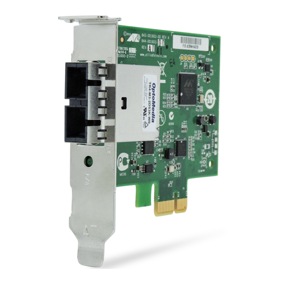
2914 Series Fiber Network Adapters with WoL Installation and User’s Guide Description The 2914 fiber network adapter series is a 100/1000Mb Ethernet PCI Express (PCIe) card equipped with one fiber optic port or SFP slot. The AT-2914GP/SP model comes with one copper port with Power over Ethernet (PoE) capability in addition to the SFP fiber slot. -
Page 17: 2914 Series Products
Chapter 1: Introduction 2914 Series The AT-2914 series includes the following models: Products AT-2914SX/SC network adapter AT-2914SX/LC network adapter AT-2914SP network adapter AT-2914GP/SP network adapter The AT-2914GP/SP model can use the optional power supply: AT-2914GP-PSU power supply unit ... -
Page 18: Sfp Slot
2914 Series Fiber Network Adapters with WoL Installation and User’s Guide The duplex LC port has the following cable requirements: 50/125 µm (core/cladding) multimode fiber optic cable up to 500m 62.5/125 µm (core/cladding) multimode fiber optic cable up to ... -
Page 19: Twisted Pair Copper Port
Chapter 1: Introduction Twisted Pair The AT-2914GP/SP network adapter is equipped with a PoE+ copper port for a 10/100/1000BASE-T twisted pair cable. See Figure 6. Copper Port LED for Twisted Pair Port LED for Fiber Optic Port Figure 6. Twisted Pair Port and LEDs The minimum cable requirement for the AT-2914GP/SP network adapter is a TIA/EIA 568-B-compliant Enhanced 5 (Cat 5e) unshielded cable. -
Page 20: The At-2914Gp/Sp Network Adapter
The adapter appears to the PC as a single port network adapter, like other 2914 series adapters. The data from the copper port and the PC is routed directly to the fiber port without any interaction from the system. -
Page 21: At-2914Gp-Psu Power Cord
Chapter 1: Introduction AT-2914GP-PSU When the optional AT-2914GP-PSU power cord is plugged into an AC power supply and connected to the AT-2914GP/SP adapter, the adapter Power Cord can provide a Powered Device (PD) connected to the adapter through the copper port up to 25.5W of power. Without the AT-2914GP-PSU power supply unit, the AT-2914GP/SP adapter provides the PD with limited power, depending on the capability of the system's PCIe 12V power rail. - Page 22 2914 Series Fiber Network Adapters with WoL Installation and User’s Guide The AT-2914GP/SP adapter can be used to add VLAN & QoS Priority tags to the phone and/or PC data traffic. To add VLAN & QoS Priority tags, see Chapter 4, “Configuring the VLAN and Priority”...
-
Page 23: Model Naming Conventions
Chapter 1: Introduction Model Naming Conventions The hardware features of the 2914 series network adapters are represented by the letters and numbers in the model names. The conventions for the 2914 series network adapters are identified in Figure 9. Figure 9. 2914 Series Model Naming Conventions The conventions are defined in Table 3. -
Page 24: Supported Operating Systems
Linux 2.6/3.x The 2914 series network adapter that is installed on Linux systems uses Linux inbox driver software to operate so that you do not need to install driver software for Linux systems. A driver supplied with an operating system is called an inbox driver. -
Page 25: Accessing Documents
Chapter 1: Introduction Accessing Documents Documents for the 2914 series network adapters are available at the Allied Telesis websites. To access documents for 2914 series network adapters, do the following: 1. Open a web browser, such as Internet Explorer or FireFox, on your system and enter the following: http://www.alliedtelesis.com/... -
Page 26: Contents Of Your Shipment
2914 Series Fiber Network Adapters with WoL Installation and User’s Guide Contents of Your Shipment The following items are Included with your network adapter: Antistatic bag The network adapter is shipped in an antistatic bag. It protects the network adapter when stored or shipped. Keep the network adapter in its packaging until ready for installation. -
Page 27: Warranty Registration
Warranty Registration Allied Telesis hardware products are covered under limited warranties. All Allied Telesis warranties are subject to and provided only on the terms and conditions set out in the Allied Telesis. For more information, visit the Allied Telesis website at:... - Page 28 2914 Series Fiber Network Adapters with WoL Installation and User’s Guide...
-
Page 29: Chapter 2: Installing The Hardware
Chapter 2 Installing the Hardware This chapter contains the following sections: “System Requirements” on page 30 “Reviewing Safety Precautions” on page 31 “Pre-Installation Checklist” on page 33 “Replacing the Bracket” on page 34 “Installing a Network Adapter” on page 36 ... -
Page 30: System Requirements
2914 Series Fiber Network Adapters with WoL Installation and User’s Guide System Requirements Before installing the 2914 series network adapter, make sure your system meets the requirements listed below: PC with one of the following operating systems: – Windows 10 in 64-bit; Microsoft certified –... -
Page 31: Reviewing Safety Precautions
Note indicates that a translation of the safety statement is available in a PDF document titled “Translated Safety Statements” posted on the Allied Telesis website at www.alliedtelesis.com/ support/software/. Warning Do not stare into the laser beam. ... - Page 32 2914 Series Fiber Network Adapters with WoL Installation and User’s Guide Warning The module is being installed in a system that operates with voltages that can be lethal. Before you remove the cover of your system, you must observe the following precautions to protect yourself and to prevent damage to the system components.
-
Page 33: Pre-Installation Checklist
Chapter 2: Installing the Hardware Pre-Installation Checklist Before installing the 2914 series network adapter, check the following list: 1. Check that your computer has an appropriate open PCIe slot. 2. Verify that your system is using the latest BIOS. 3. When you download the driver software from the Allied Telesis website, record the path to where the driver file resides on your system. -
Page 34: Replacing The Bracket
2914 Series Fiber Network Adapters with WoL Installation and User’s Guide Replacing the Bracket The 2914 series network adapter is shipped with the low-profile bracket attached to the adapter. Depending on your system, you may need to replace the bracket with the standard bracket. - Page 35 Chapter 2: Installing the Hardware Figure 11. Installing the Standard Bracket...
-
Page 36: Installing A Network Adapter
2914 Series Fiber Network Adapters with WoL Installation and User’s Guide Installing a Network Adapter The following instructions apply to installing a 2914 series network adapter in most systems. Refer to the manuals that were supplied with your system for details about performing these tasks on your particular system. - Page 37 Chapter 2: Installing the Hardware Figure 12. Removing the PC Cover 3. Select an empty, non-shared PCIe slot and remove the faceplate. Keep the faceplate in a safe place. You may need it for future use. See Figure 13. Figure 13. Removing the Faceplate From PCIe Slot 4.
- Page 38 2914 Series Fiber Network Adapters with WoL Installation and User’s Guide Figure 14. Inserting the Network Adapter Caution Do not use excessive force when seating the adapter, as the force may damage the system or the adapter. If the adapter resists seating, remove it from the system, realign it, and try again.
- Page 39 Chapter 2: Installing the Hardware Next, connect the network cables. See “Connecting the Network Cables” on page 41.
-
Page 40: Connecting The At-2914Gp-Psu Power Cord To The At-2914Gp/Sp Network Adapter
2914 Series Fiber Network Adapters with WoL Installation and User’s Guide Connecting the AT-2914GP-PSU Power Cord to the AT-2914GP/SP Network Adapter Using the AT-2914GP-PSU power supply unit, the adapter can provide a PD connected to the adapter through the copper port up to 25.5W of power. -
Page 41: Connecting The Network Cables
Chapter 2: Installing the Hardware Connecting the Network Cables The 2914 series network adapter is equipped with a fiber optic port. To connect the network adapter to the network, you must have a fiber optic cable with the appropriate connector. - Page 42 2914 Series Fiber Network Adapters with WoL Installation and User’s Guide After the system is connected to the network and power is supplied, the network adapter attempts to establish the connection as follow: With a Gigabit SFP, the network adapter attempts to negotiate ...
-
Page 43: Chapter 3: Installing The Driver Software
Chapter 3 Installing the Driver Software This chapter describes how to install driver software for the 2914 series network adapter onto your Windows platform. It contains the following topics: “Overview” on page 44 “Downloading the Driver Software” on page 45 ... -
Page 44: Overview
2914 Series Fiber Network Adapters with WoL Installation and User’s Guide Overview When you install the 2914 series network adapter in your computer, your next step is to install driver software onto your Windows operating system. You can install driver software using the Device Manager or the silent installation method. -
Page 45: Downloading The Driver Software
Chapter 3: Installing the Driver Software Downloading the Driver Software The driver for network adapters are available from the Allied Telesis website. To download the driver software, do the following: 1. Open a web browser, such as Internet Explorer or FireFox, on your system and enter the following: http://www.alliedtelesis.com/support/software... - Page 46 2914 Series Fiber Network Adapters with WoL Installation and User’s Guide 2. If you do not have an account for the Download center, fill the fields and click Request Guest Access. You will receive a guest login account and password via email.
- Page 47 Chapter 3: Installing the Driver Software 5. Select Product Search from the menu on the left bar as shown in Figure 19 on page 46. 6. Enter “2914” in the search box and click Search. The link to the driver for the 2914 products is listed. 7.
-
Page 48: Accessing The Device Manager
2914 Series Fiber Network Adapters with WoL Installation and User’s Guide Accessing the Device Manager To install or update the driver software for 2914 series network adapter, you must first access Device Manager. To access the Device Manager on your Windows 10 operating system, perform the following: 1. -
Page 49: Installing The Driver Software
3. Right-click Allied Telesis AT-2914 Series Fiber Ethernet. Note The Device Manager may list your adapter as a Broadcom device, or Allied Telesis device, depending on what drivers reside on your system. The shortcut menu appears. See Figure 21 as an example. - Page 50 2914 Series Fiber Network Adapters with WoL Installation and User’s Guide Figure 22. Update Driver Software Window 5. Select Browse my computer for driver software. The Update Driver Software window prompts you to enter the location of the driver folder. See Figure 23 as an example.
- Page 51 Chapter 3: Installing the Driver Software The confirmation message shown in Figure 24 appears when the driver software is successfully updated. Figure 24. Update Driver Software Window Confirmation 8. Click Close.
-
Page 52: Updating The Driver Software
2914 Series Fiber Network Adapters with WoL Installation and User’s Guide Updating the Driver Software If your operating system automatically installs a default driver or Broadcom driver, you need to update the driver software with the driver that you downloaded from the Allied Telesis website. To obtain the latest version of the AT-2914 network adapter driver, see “Downloading the... -
Page 53: Performing The Silent Installation
Note You can apply the silent installation method only to Microsoft certified drivers. The drivers that Allied Telesis provides for the AT- 2914 network adapters are all Microsoft certified. Use a command line utility called Driver package Installer (DPInst) for the silent installation. -
Page 54: Viewing Supported Dpinst Options
2914 Series Fiber Network Adapters with WoL Installation and User’s Guide 8. Install the driver in the silent mode by entering the following command: > dpinst /S Note Adding the /S switch to the dpinst command suppresses the display of wizard pages, user dialog boxes, and other user intervention requests. -
Page 55: Chapter 4: Configuring The Vlan And Priority
Chapter 4 Configuring the VLAN and Priority This chapter describes how to access the CLI on the AT-2914GP/SP network adapter and change the VLAN and priority settings. It contains the following topics: “Overview” on page 56 “Accessing the CLI on the AT-2914GP/SP Network Adapter” on ... -
Page 56: Overview
2914 Series Fiber Network Adapters with WoL Installation and User’s Guide Overview The AT-2914GP/SP network adapter has an internal CLI for you to modify the VLAN and priority settings through the Console port. To access the CLI, connect the adapter to your management PC and install a virtual serial port driver. -
Page 57: Accessing The Cli On The At-2914Gp/Sp Network Adapter
Chapter 4: Configuring the VLAN and Priority Accessing the CLI on the AT-2914GP/SP Network Adapter To modify VLAN and Priority settings on the AT-2914GP/SP adapter, you must access the CLI on the adapter. Guidelines Here are the guidelines for modifying the VLAN and priority settings of AT-2914GP/SP adapter by accessing the CLI: To install or update serial port driver software, you must have ... -
Page 58: Installing The Serial Port Driver Manually
2914 Series Fiber Network Adapters with WoL Installation and User’s Guide Figure 26. COM Ports In the Device Manager 5. If you do not see a Silicon Lab device in the list, the serial port driver installation failed. Go to “Installing the Serial Port Driver Manually” on page 58 to download and install the driver. -
Page 59: Accessing The Cli Using A Terminal Emulator Program
Chapter 4: Configuring the VLAN and Priority Accessing the To access the CLI on the adapter to modify VLAN and priority settings, perform the following procedure: CLI Using a Terminal 1. Connect the USB-A connector of the cable to the USB-A receptacle on Emulator a management PC. -
Page 60: Configuring The Vlan And Priority Settings On The Network Adapter
2914 Series Fiber Network Adapters with WoL Installation and User’s Guide Configuring the VLAN and Priority Settings on the Network Adapter You can specify or modify the VLAN and Priority settings on the AT-2914GP/SP adapter through the CLI. See Table 4. -
Page 61: Enabling The Vlan Tagging
Chapter 4: Configuring the VLAN and Priority Enabling the When the VLAN tagging is enabled on the adapter, VLAN and Priority tags are added to Ethernet frames. VLAN Tagging Note Make sure that the Priority & VLAN setting in the Advanced Properties is disabled. -
Page 62: Changing The Vlan Id For The Poe Copper Port
2914 Series Fiber Network Adapters with WoL Installation and User’s Guide 5. Close the serial console and power down the system. 6. Remove and re-install the AT-2914GP/SP network adapter. 7. Power on the system. The VLAN Tagging is now disabled. -
Page 63: Changing The Vlan Id For The Pc Traffic
Chapter 4: Configuring the VLAN and Priority 4. Press Enter to continue. Changing the You can specify the VLAN ID for the PC traffic. The default setting is 0. VLAN ID for the To specify the VLAN ID for the PC traffic, perform the following procedure: PC Traffic 1. - Page 64 2914 Series Fiber Network Adapters with WoL Installation and User’s Guide...
-
Page 65: Chapter 5: Configuring A Voip Phone System
Chapter 5 Configuring a VoIP Phone System This chapter describes how to configure a VoIP phone system using the AT-2914GP/SP network adapter. It contains the following topics: “Overview” on page 66 “Configuring VLAN Tagging on Adapter Ports” on page 67 ... -
Page 66: Overview
2914 Series Fiber Network Adapters with WoL Installation and User’s Guide Overview The AT-2914GP/SP network adapter is installed on a PC and connects the PC to the Ethernet network through the fiber optic port and a Powered Device (PD) through the PoE+ copper port. A PD is a device powered through an Ethernet cable by a Power Supply Equipment (PSE). -
Page 67: Configuring Vlan Tagging On Adapter Ports
Chapter 5: Configuring a VoIP Phone System Configuring VLAN Tagging on Adapter Ports To separate voice traffic coming from the VoIP phone from data traffic from the PC, several combinations of VLAN tagging settings are possible. VLAN Tagging Figure 29 illustrates possible VLAN tagging combinations. In this example, voice frames belong to the VLAN 150 and data frames belong to the VLAN Combinations 10 except Config. -
Page 68: Using Vlan-Capable Voip Phones To Set Up Vlan
2914 Series Fiber Network Adapters with WoL Installation and User’s Guide Using Some VoIP phones are capable of VLAN tagging. In Config 1 using a VLAN-capable VoIP phone, you may assign the VLAN ID 150 using the VLAN-Capable VoIP phone setting. Voice frames get the VLAN tagged at the phone, are VoIP Phones to sent to the copper port and transmitted to the switch through the fiber port. -
Page 69: Chapter 6: Modifying Advanced Properties
Chapter 6 Modifying Advanced Properties This chapter includes the following topics: “Overview” on page 70 “Accessing Advanced Properties” on page 71 “802.3az EEE” on page 72 “ARP Offload” on page 73 “Ethernet@WireSpeed” on page 74 “Flow Control”... -
Page 70: Overview
2914 Series Fiber Network Adapters with WoL Installation and User’s Guide Overview The 2914 series network adapters allow you to modify advanced properties to meet your requirements. To access the advanced properties, access Device Manager, then go to each advanced property page. -
Page 71: Accessing Advanced Properties
1. Access Device Manager. See “Accessing the Device Manager” on page 48. 2. In the Device Manager window, double-click Allied Telesis AT-2914 Series Fiber Ethernet. The properties window pops up. 3. Click the Advanced tab. -
Page 72: Az Eee
2914 Series Fiber Network Adapters with WoL Installation and User’s Guide 802.3az EEE The 802.3az EEE (Energy Efficient Ethernet) property allows you to optimize the energy usage of the interface over Ethernet. Note The setting is always disabled on the 2914 series adapter. -
Page 73: Arp Offload
Chapter 6: Modifying Advanced Properties ARP Offload The ARP Offload feature enables the adapter not to wake up when responding to an ARP request. ARP is used to verify whether a computer is still present on the network and resolve an IP address into a MAC address. -
Page 74: Ethernet@Wirespeed
2914 Series Fiber Network Adapters with WoL Installation and User’s Guide Ethernet@WireSpeed The Ethernet@WireSpeed feature connects two devices even when the devices are connected through an impaired copper cable. Note The setting is always disabled on the 2914 series adapter. -
Page 75: Flow Control
Chapter 6: Modifying Advanced Properties Flow Control The Flow Control feature allows you to control the flow between the AT-2914 adapter port and its link partner. You can enable or disable the adapter port to process received PAUSE frames and transmit PAUSE frames. - Page 76 2914 Series Fiber Network Adapters with WoL Installation and User’s Guide Tx & Rx Enabled — The adapter processes ingress PAUSE frames and transmits PAUSE frames. Rx Enabled — The adapter processes ingress PAUSE frames, but does not transmit PAUSE frames.
-
Page 77: Interrupt Moderation
Chapter 6: Modifying Advanced Properties Interrupt Moderation The Interrupt Moderation feature allows you to limit the rate of interrupts to the CPU during packet transmission and packet reception. When this feature is enabled, interrupts are handled as a group so that the CPU utilization decreases;... -
Page 78: Jumbo Mtu
2914 Series Fiber Network Adapters with WoL Installation and User’s Guide Jumbo Mtu The Jumbo Mtu (Maximum transmission unit) feature allows you to specify the maximum size of Ethernet frames that the adapter port supports. The network performance usually improves when the larger frame size is specified;... -
Page 79: Large Send Offload V2 (Ipv4)
Chapter 6: Modifying Advanced Properties Large Send Offload v2 (IPv4) The Large Send Offload v2 (IPv4) feature allows you to control the load of sending out large packets. When this feature is enabled, the adapter port segments large packets for IPv4 traffic and reduces the CPU load. This feature, which supports large packets up to 256kb, overrides the Large Send Offload (IPv4) feature if both features are enabled. -
Page 80: Large Send Offload V2 (Ipv6)
2914 Series Fiber Network Adapters with WoL Installation and User’s Guide Large Send Offload v2 (IPv6) The Large Send Offload v2 (IPv6) feature allows you to control the load of sending out large packets. When this feature is enabled, the adapter port segments large packets for IPv6 traffic and reduces the CPU load. -
Page 81: Maximum Number Of Rss Queues
Chapter 6: Modifying Advanced Properties Maximum Number of RSS Queues The RSS Queues feature assigns data to queues associated with physical CPU cores. You can specify the maximum number of RSS queues that the network adapter assigns receiving data to. To specify or change the maximum number of RSS Queues, do the following: 1. - Page 82 2914 Series Fiber Network Adapters with WoL Installation and User’s Guide RSS 4 Queues — The system allocates up to four RSS queues. RSS 1 Queue — The system allocates up to one RSS queue. RSS 2 Queue — The system allocates up to two RSS queues.
-
Page 83: Network Address
Chapter 6: Modifying Advanced Properties Network Address The Network Address property allows you to replace the MAC address originally assigned to the adapter with a user-defined address. The user- defined address that you assign to the adapter is called a locally administered address. - Page 84 2914 Series Fiber Network Adapters with WoL Installation and User’s Guide 3. In the Value text box, enter a locally administered address for the AT-2914 network adapter. By default, no locally administered address is assigned. Here are guidelines to assigning a locally administered address: The address must be unique.
-
Page 85: Ns Offload
Chapter 6: Modifying Advanced Properties NS Offload The NS (Neighbor Solicitation) Offload feature enables the adapter not to wake up when responding to an NS request. To enable or disable the NS Offload feature, do the following: 1. Access the Advanced Properties. See “Accessing Advanced Properties”... -
Page 86: Priority & Vlan
2914 Series Fiber Network Adapters with WoL Installation and User’s Guide Priority & VLAN The Priority & VLAN feature allows you to control sending and receiving tagged frames of QoS and VLAN. When the property is set to Priority & VLAN Enabled, the adapter sends and receives QoS and VLAN tagged frames;... - Page 87 Chapter 6: Modifying Advanced Properties 3. Select one of the following options: Priority & VLAN Enabled — The adapter sends and receives QoS and VLAN tagged frames. This is the default setting. Priority & VLAN Disabled — The adapter does not send and ...
-
Page 88: Receive Side Scaling
2914 Series Fiber Network Adapters with WoL Installation and User’s Guide Receive Side Scaling The Receive Side Scaling (RSS) feature allows the adapter to efficiently distribute receive processing across multiple CPU’s and to prevent from overloading a single CPU. To make this feature effective, the computer must have multiple CPU’s in a multiprocessor system. -
Page 89: Speed & Duplex
Speed & Duplex The Speed & Duplex property is set to Auto-negotiation. Note The setting is always Auto-negotiation for the 2914 series adapter. When the system is connected to the network and power is supplied, a network adapter attempts as follows: The AT-2914SX/SC and AT-2914SX/LC adapters attempt to ... - Page 90 2914 Series Fiber Network Adapters with WoL Installation and User’s Guide Figure 44. Speed & Duplex Page 3. Click OK.
-
Page 91: Tcp/Udp Checksum Offload (Ipv4)
Chapter 6: Modifying Advanced Properties TCP/UDP Checksum Offload (IPv4) The TCP/UDP Checksum Offload (IPv4) function enables the adapter port to compute the checksum of transmitting IPv4 packets and verify the checksum of receiving IPv4 packets, taking load off from the CPU. To modify the TCP/UDP Checksum Offload (IPv4) setting, do the following: 1. - Page 92 2914 Series Fiber Network Adapters with WoL Installation and User’s Guide Rx Enabled — Enables the TCP/UDP Checksum Offload (IPv4) function only for receiving IPv4 packets. Tx Enabled — Enables the TCP/UDP Checksum Offload (IPv4) function only for transmitting IPv4 packets.
-
Page 93: Tcp/Udp Checksum Offload (Ipv6)
Chapter 6: Modifying Advanced Properties TCP/UDP Checksum Offload (IPv6) The TCP/UDP Checksum Offload (IPv6) function enables the adapter port to compute the checksum of transmitting IPv6 packets and verify the checksum of receiving IPv6 packets, taking load off from the CPU. To enable or disable the TCP/UDP Checksum Offload (IPv6) feature, do the following: 1. - Page 94 2914 Series Fiber Network Adapters with WoL Installation and User’s Guide Rx Enabled — Enables the TCP/UDP Checksum Offload (IPv6) function only for receiving IPv6 packets. Tx Enabled — Enables the TCP/UDP Checksum Offload (IPv6) function only for transmitting IPv6 packets.
-
Page 95: Vlan Id
Chapter 6: Modifying Advanced Properties VLAN ID The VLAN ID property allows you to specify a VLAN ID on your network to the adapter port. The adapter port adds the value of the VLAN ID to a frame in the VLAN tag before transmitting the frame. To change the VLAN ID value, do the following: 1. -
Page 96: Wake On Magic Packet
2914 Series Fiber Network Adapters with WoL Installation and User’s Guide Wake on Magic Packet The Wake on Magic Packet feature enables the adapter to wake up from a low-power mode when the adapter port receives a Magic packet. To enable or disable the Wake on Magic Packet feature, do the following: 1. -
Page 97: Wake On Pattern Match
Chapter 6: Modifying Advanced Properties Wake on Pattern Match The Wake on Pattern Match feature enables the network adapter to wake up from a low-power mode when the packet matches the wake patterns specified in the operating system. To enable of disable the Wake on Pattern Match feature, do the following: 1. -
Page 98: Wol Speed
2914 Series Fiber Network Adapters with WoL Installation and User’s Guide WOL Speed The WOL Speed property allows you to specify the speed of Wake-on- LAN on your adapter port. This speed does not affect the speed of the fiber connection to your network. -
Page 99: Chapter 7: Uninstalling The Driver Software
Chapter 7 Uninstalling the Driver Software This chapter describes how to uninstall the driver software for the 2914 series network adapter. This chapter contains the following topics: “Overview” on page 100 “Uninstalling the Driver Software Using Device Manager” on page 101 ... -
Page 100: Overview
2914 Series Fiber Network Adapters with WoL Installation and User’s Guide Overview When you no longer use the AT-2914 network adapter for your computer, you can uninstall the driver software from your operating system. As you can install driver software for the AT-2914 network adapter using... -
Page 101: Uninstalling The Driver Software Using Device Manager
See “Accessing the Device Manager” on page 48. 3. In the Device Manager window, expand the Network Adapters folder. 4. Right-click the Allied Telesis AT-2914 Series Fiber Ethernet. The shortcut menu appears as shown in Figure 51. Figure 51. Device Manager Shortcut Menu 5. -
Page 102: Uninstalling The Driver Software Silently
2914 Series Fiber Network Adapters with WoL Installation and User’s Guide Uninstalling the Driver Software Silently You can apply the silent installation method to uninstall the driver. To uninstall the driver without user-intervention, perform the following steps: 1. Open a command prompt window with administrator privileges. -
Page 103: Chapter 8: Troubleshooting
Chapter 8 Troubleshooting This chapter describes troubleshooting procedures. It contains the following sections: “Checking the Port LED on the Adapter” on page 104 “Fiber Optic Ports” on page 105 “Twisted Pair Ports” on page 107 “Testing Network Connectivity” on page 109 ... -
Page 104: Checking The Port Led On The Adapter
2914 Series Fiber Network Adapters with WoL Installation and User’s Guide Checking the Port LED on the Adapter This section describes the states of the LEDs. LED on The 2914 series network adapter except the AT-2914GP/SP model comes with one LED. The LED indicates the link and activity status for the port. -
Page 105: Fiber Optic Ports
The TX port of the fiber connector on the 2914 series network adapter has the same wavelength as the RX port of the link partner and the RX port on the 2914 series network adapter has the same wavelength as the TX port of the link partner. - Page 106 2914 Series Fiber Network Adapters with WoL Installation and User’s Guide Remove all other adapter cards from the system and run the tests again. If the adapter card passes the tests, the other adapter cards may be causing contention.
-
Page 107: Twisted Pair Ports
Chapter 8: Troubleshooting Twisted Pair Ports The following are troubleshooting suggestions for the PoE+ RJ-45 twisted pair port on the AT-2914GP/SP network adapter: Problem 1: The network adapter is connected to the AT-2914GP-PSU power adapter but is not providing power to the powered device on the RJ-45 twisted pair port. - Page 108 2914 Series Fiber Network Adapters with WoL Installation and User’s Guide Verify that the powered device supports Mode A of the IEEE 802.3at standard. Mode A is one of two modes that define the connector pins that deliver the power from the port in the network adapter to the powered device.
-
Page 109: Testing Network Connectivity
Chapter 8: Troubleshooting Testing Network Connectivity This section describes how to test network connectivity for Windows and Linux networks. Guidelines Here are guidelines to the adapter and switch settings: When you are using the fiber optic port or a Gigabit SFP, both the ... -
Page 110: Linux
2914 Series Fiber Network Adapters with WoL Installation and User’s Guide 4. Type ping <IP address> from the command line, then press Enter. The network connectivity information is displayed, as shown in Figure 53. Figure 53. Command Window with ping displayed... -
Page 111: Appendix A: Specifications
5% to 90% (non-condensing) Altitude: 3,048 m (10,000 ft.) Power Specifications Table 9. Power Specifications Voltage Power Consumption 2914 Series 3.3V 2.0 watts Requirement for AT-2914GP/SP when Up to 36 watts supplying power to PD device (Depending on PoE load) -
Page 112: Optical Specifications
2914 Series Fiber Network Adapters with WoL Installation and User’s Guide Optical Specifications Here are the operating specifications for the duplex SC port on the AT-2914SX/SC network adapter: Output Optical Power: -9.5 (Min) -4 (Max) dBM Optical Sensitivity: -20 (Typ) -
Page 113: Rj-45 Twisted Pair Port Pinouts
Appendix A: Specifications RJ-45 Twisted Pair Port Pinouts Figure 54 illustrates the pin layout of the RJ-45 connector on the AT- 2914GP/SP network adapter: Figure 54. Pin Layout (Front View) of Twisted Pair Port Table 10 lists the pin signals at 10/100Mbps. Table 10. - Page 114 2914 Series Fiber Network Adapters with WoL Installation and User’s Guide Table 11. Pin Signals at 1000Mbps on the Twisted Pair Port (Continued) TX and RX+ TX and RX- TX and RX- TX and RX+ TX and RX-...
Need help?
Do you have a question about the 2914 Series and is the answer not in the manual?
Questions and answers