
Related Manuals for Extron electronics USB Extender Plus Series


Summary of Contents for Extron electronics USB Extender Plus Series
- Page 1 User Guide USB Extenders USER MANUAL USB Extender Plus Series Twisted Pair Extenders for USB Peripherals 68-2652-01 Rev. G 04 17...
- Page 2 Safety Instructions Safety Instructions • English Istruzioni di sicurezza • Italiano WARNING: This symbol, , when used on the product, is intended to AVVERTENZA: Il simbolo, , se usato sul prodotto, serve ad alert the user of the presence of uninsulated dangerous voltage within avvertire l’utente della presenza di tensione non isolata pericolosa the product’s enclosure that may present a risk of electric shock.
- Page 3 ついては、 エクス トロンのウェブサイ ト より 『Extron Safety www.extron.com and Regulatory Compliance Guide』 (P/N 68-290-01) をご覧ください。 © 2017 Extron Electronics. All rights reserved. Trademarks All trademarks mentioned in this guide are the properties of their respective owners. The following registered trademarks( ®...
- Page 4 FCC Class A Notice This equipment has been tested and found to comply with the limits for a Class A digital device, pursuant to part 15 of the FCC rules. The Class A limits provide reasonable protection against harmful interference when the equipment is operated in a commercial environment.
- Page 5 Conventions Used in this Guide Notifications The following notifications are used in this guide: ATTENTION: • Risk of property damage. • Risque de dommages matériels. NOTE: A note draws attention to important information. Software Commands Commands are written in the fonts shown here: ^AR Merge Scene,,0p1 scene 1,1 ^B 51 ^W^C.0 [01] R 0004 00300 00400 00800 00600 [02] 35 [17] [03] E X! *X1&* X2)* X2#* X2!
-
Page 7: Table Of Contents
Receiver (Point-to-Point Only) ...... 12 Twisted Pair Cable Termination ......37 Connecting for Serial Communication ... 13 Mounting the USB Extender Plus Series ... 38 Connecting over the Network ....... 14 Mounting USB Extender Plus Standard and HID Only ..........38 Pairing a Transmitter to Multiple Receivers .. - Page 8 USB Extender Plus Series • Contents viii...
-
Page 9: Introduction
Introduction This section provides an overview of the USB Extender Plus Series User Guide and the following products: • USB Extender Plus (rack-mountable) • USB Extender Plus HID Only USB Extender Plus AAP • • USB Extender Plus D The following topics are discussed: •... -
Page 10: Features
Extends human interface devices — The USB Extender Plus HID-only models • extend the usable distance of smart card readers and USB human interface peripheral devices that do not require special USB device drivers, including a standard keyboard, mouse, hub, and other devices. USB Extender Plus Series • Introduction... -
Page 11: Application Diagrams
USB EXTENDER Plus R Rx 3 STATUS LINK PAIR CONFIG HOST USB EXTENDER Plus R Rx 4 (running PCS 3.3 or higher software) Figure 2. USB Extender Plus using a Network Connection with Multiple Receivers USB Extender Plus Series • Introduction... - Page 12 Laptop STATUS HOST LINK HOST Extron USB Extender Plus AAP T Twisted Pair Extender for USB Peripherals USB EXTENDER Plus AAP T Figure 3. Application with Mixed USB Extenders Plus AAP and D Models USB Extender Plus Series • Introduction...
-
Page 13: Installation And Operation
Transmitter Rear Panels — USB Extender Plus T, Standard and HID-only POWER 1.0 A MAX HOST Power connector Twisted Pair Output Connector Host (Input) connector Figure 4. Transmitter Rear Panel Connectors (Rack Mountable Models) USB Extender Plus Series • Installation and Operation... -
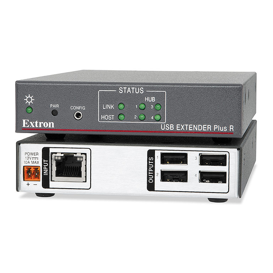
Page 14: Receiver Rear Panels - Usb Extender Plus R, Standard And Hid-Only
USB Hub connectors — The built-in four port hub has four female USB Type A connectors. The connections are USB 3.0 compatible, providing +5 VDC at up to 500 mA to connected USB peripherals requiring power. USB Extender Plus Series • Installation and Operation... -
Page 15: Transmitter And Receiver Rear Panels - Usb Extender Plus Aap And Decorator-Style
NOTE: The rear panel of the USB Extender Plus AAP receiver is identical to that of the transmitter except for the function of the RJ-45 connector. On the transmitter, this connector is used for output, while on the receiver it is used for input. USB Extender Plus Series • Installation and Operation... - Page 16 Using the Configuration Software, beginning on page 27, for more information). • For point-to-point non-network applications, pairing must be done before operation the first time the transmitter and receiver are used together. USB Extender Plus Series • Installation and Operation...
-
Page 17: Power Supply Attention Notices
Si ce produit ne dispose pas de sa propre source d’alimentation électrique, il doit être alimenté par une source d’alimentation de classe 2 ou LPS et paramétré à 12 V et 1.0 A minimum. USB Extender Plus Series • Installation and Operation... -
Page 18: Cabling And Setup
+12 VDC +12 VDC External External Power Supply Power Supply (12 VDC, 1 A ) (12 VDC, 1 A ) Figure 8. USB Extender Plus T-R Connection with Two External Power Supplies USB Extender Plus Series • Installation and Operation... -
Page 19: Installation Procedure
USB and host Rack-mountable has been established. HOST Models Connect a CATx twisted pair cable from the RJ-45 Output port of the transmitter ( ) to the Input port of the receiver ( USB Extender Plus Series • Installation and Operation... -
Page 20: Pairing And Unpairing The Transmitter And Receiver (Point-To-Point Only)
Release the button. Pair Repeat steps 1 and 2 for each transmitter and receiver. Proceed with the pairing (see Pairing the transmitter and receiver on the next page). USB Extender Plus Series • Installation and Operation... -
Page 21: Connecting For Serial Communication
The port protocol is 9600 baud, 8 data bits, 1 stop bit, and no parity. USB Extender Plus Series • Installation and Operation... -
Page 22: Connecting Over The Network
The USB Extender Plus series is compatible with both managed and unmanaged network switchers. • Multicast and Unicast do not apply to the USB Extender Plus series. This series features its own proprietary technology when the 1:N feature is enabled. •... - Page 23 • When using the USB Extender Plus series over-the-network or 1:N pairing, you can use only one high speed device at a time to one transmitter. High speed USB devices include webcams, audio devices, external hard drives, and so on.
-
Page 24: Pairing A Transmitter To Multiple Receivers
• To disable: E E 0 USBC • To enable: E E 1 USBC Remote Configuration and Control, beginning on page 22, for information on entering SIS commands. USB Extender Plus Series • Installation and Operation... -
Page 25: Front Panel Features
Transmitter Front Panel, Rack-mountable Models STATUS HOST LINK HOST USB EXTENDER Plus AAP T A A A Power LED Link LED Host Port Host LED Figure 16. Transmitter Front Panel, AAP Model USB Extender Plus Series • Installation and Operation... - Page 26 While the transmitter is being paired with the receiver, this LED blinks. When the pairing process is completed, the LED lights steadily. Host LED — This green LED lights when the transmitter is powered and is communicating with the host PC. USB Extender Plus Series • Installation and Operation...
-
Page 27: Receiver Front Panels
A A A Figure 19. Receiver Front Panel, AAP Models Power LED Host LED Link LED Extron Hub LEDs USB Hub connectors STATUS HOST LINK Figure 20. Receiver Front Panel, Decorator-Style Models USB Extender Plus Series • Installation and Operation... -
Page 28: System Operation
If problems are encountered, ensure all cables are routed and connected properly and the latest drivers for each peripheral are installed. USB Extender Plus Series • Installation and Operation... -
Page 29: Troubleshooting
LEDs are on, but no USB devices are connected. Lights when a connected A peripheral device connected peripheral is recognized by to the USB port has not been the host PC. recognized or is improperly connected. USB Extender Plus Series • Installation and Operation... -
Page 30: Remote Configuration And Control
Extender-initiated Message When power is applied to the extender or after the unit has been reset via SIS, it sends the following copyright message: (C)Copyright 20nn, Extron Electronics, USB Extender Plus Series, Vn.nn, 60-nnnn-nn where is the firmware version number and 60- is the unit part number. -
Page 31: Error Responses
ASCII to Hexadecimal Conversion The ASCII to Hex Conversion Table below is for use with the Command and Response Table. ASCII to HEX Conversion Table Space • USB Extender Plus Series • Remote Configuration and Control... -
Page 32: Symbol Definitions
192.168.254.254 = Subnet mask (Default is 255.255.0.0 = Gateway IP address (Default is 0.0.0.0 = Port number for Config port (Default is 6137 NOTE: Unless otherwise indicated, commands are not case-sensitive. USB Extender Plus Series • Remote Configuration and Control... -
Page 33: Command And Response Table For Sis Commands
IP settings. Absolute system reset Reset all extender settings to factory ZQQQ defaults except firmware version. Upload Firmware Upload firmware ...go UPLOAD is displayed after the upload is complete. USB Extender Plus Series • Remote Configuration and Control... - Page 34 Pmap K 06137 factory default (06137). Disable Config port Disable the Config port. K 0 PMAP Pmap K 00000 View Config port map X^ ] View the current Config port number. K PMAP USB Extender Plus Series • Remote Configuration and Control...
-
Page 35: Using The Configuration Software
Open the Extron Web page and select the tab. Download On the screen, click the link on the left sidebar menu (see Download Center figure 21, Figure 21. Software Links on the Download Page of the Extron Website USB Extender Plus Series • Remote Configuration and Control... - Page 36 By default, the installation creates a folder called “Extron PCS” at: c:\Program Files (x86)\Extron\Extron PCS c:\Program Files\Extron\Extron PCS If there is not already an Extron folder in your Program Files folder, the installation program creates it as well. USB Extender Plus Series • Remote Configuration and Control...
-
Page 37: Setting Up Network Operation
Command Prompt Window with IP Information Use the PCS configuration software or SIS commands to set the IP address, gateway address, and subnet mask as needed (see figure 27 on page 32). USB Extender Plus Series • Remote Configuration and Control... -
Page 38: Starting The Configuration Program
The following screen appears: Figure 24. Software Version Number on the About PCS Screen After ensuring that the software version is 3.3 or higher (see figure 24, ), click to close the window. USB Extender Plus Series • Remote Configuration and Control... - Page 39 New Configuration File Plus devices on your network. On this list, click the name of the USB extender to be configured. Figure 26. Selecting an Extender from the New Configuration File List USB Extender Plus Series • Remote Configuration and Control...
- Page 40 9600). Click the button ( ) at the bottom of the screen. The Connect Device Settings screen for your USB Extender Plus opens, showing all the current extender settings. USB Extender Plus Series • Remote Configuration and Control...
- Page 41 USB Extenders Device Directory Extender Plus devices are not listed separately.) You can now proceed to pair the transmitter and receivers (see Making Ties Using the Configuration Program on the next page). USB Extender Plus Series • Remote Configuration and Control...
-
Page 42: Making Ties Using The Configuration Program
Selecting USB Extenders on the Device Discovery Panel Click in the panel (see figure 30, USB Extenders Device Directory Click ). The screen appears (see figure 31 on the next page). Connect Ties USB Extender Plus Series • Remote Configuration and Control... - Page 43 MAC address. To display the addresses of tied products, hover the cursor over the green connection box in the matrix. The addresses of both tied products are displayed in a pop-up ( USB Extender Plus Series • Remote Configuration and Control...
- Page 44 Repeat step 2 for any additional receivers in the same row that you want to pair with the selected transmitter. Repeat steps 1 through 3 for any additional transmitters to which receivers will be paired. USB Extender Plus Series • Remote Configuration and Control...
-
Page 45: Reference Information
NOTE: Do not use Extron UTP23SF-4 Enhanced Skew-Free AV UTP cable to link the transmitter and receiver. Skew-free AV cable is designed for Extron TP transmitter and receiver AV applications. The USB Extender Series does not work properly with this cable. USB Extender Plus Series • Reference Information... -
Page 46: Mounting The Usb Extender Plus Series
• Through furniture — The transmitter or receiver can be mounted through a desk or other furniture using an optional Extron Through-Desk Mounting Kit for quarter-rack or half-rack width products (see www.extron.com). USB Extender Plus Series • Reference Information... -
Page 47: Mounting Usb Extenders Plus Aap And D
Run the TP and power supply wires into the wall, furniture, or conduits before installing the wall plate. • Follow the instructions provided with the junction box to install it. NOTE: The Decorator-Style series mounts in a standard single-gang junction box. USB Extender Plus Series • Reference Information... - Page 48 L IN L IN USB Extender lu s Plus Decorator-Style AAP 314 USB Extender Plus AAP Figure 36. Mounting a USB Extender Plus AAP and Decorator-Style to an AAP Frame and a Mud Ring USB Extender Plus Series • Reference Information...
-
Page 49: Extron Warranty
Extron Electronics makes no further warranties either expressed or implied with respect to the product and its quality, performance, merchantability, or fitness for any particular use. In no event will Extron Electronics be liable for direct, indirect, or consequential damages resulting from any defect in this product even if Extron Electronics has been advised of such damage.
Need help?
Do you have a question about the USB Extender Plus Series and is the answer not in the manual?
Questions and answers