
Related Manuals for Extron electronics VGAUXGA Line Drivers With Audio Extender Series


Summary of Contents for Extron electronics VGAUXGA Line Drivers With Audio Extender Series
- Page 1 User’s Manual Extender Series VGA –UXGA Line Drivers With Audio 68-552-01 Rev. J 06 08...
- Page 2 Safety Instructions • English This symbol is intended to alert the user of important operating and maintenance (servicing) instructions in the literature provided with the equipment. This symbol is intended to alert the user of the presence of uninsulated dangerous voltage within the product’s enclosure that may present a risk of electric shock.
- Page 3 安全须知 • 中文 这个符号提示用户该设备用户手册中 有重要的操作和维护说明。 这个符号警告用户该设备机壳内有暴 露的危险电压,有触电危险。 注意 阅读说明书 • 用 户 使 用 该 设 备 前 必 须 阅 读 并 理 解 所 有 安 全 和 使 用 说 明 。 保存说明书 • 用户应保存安全说明书以备将来使 用。 遵守警告 • 用户应遵守产品和用户指南上的所有安 全和操作说明。...
- Page 5 Quick Start Guide — Extender Series Installation and service must be performed by authorized personnel only. These products must be used with UL approved, grounded electrical boxes. Step 1 Turn all of the equipment off and disconnect the power cords from the power source.
- Page 6 Connect power and turn the equipment Step 6 Test the system and set the gain switch. Ensure that Installation Cable all devices receive power. Check and adjust cabling and gain as needed. See “Gain switch” on page 2-12. Medium – Mid-level...
-
Page 7: Table Of Contents
Chapter One • Introduction About this Manual About the Extender Series VGA Line Drivers Differences between the models ... 1-2 Features ... 1-3 Chapter Two • Installation UL Requirements Installation Instructions Preparing the Site and Installing the Wall Box Front Panel Features and Cabling Top/Rear/Bottom panel Features and Cabling Mounting the Extenders Mounting the Extender AAP or Extender AAP EX into an... - Page 8 Table of Contents, cont’d Extender AKM UK dimensions ... B-7 Extender AKM MAAP dimensions ... B-8 Extender D dimensions ... B-9 Templates ... B-10 Extender WM template ... B-10 Extender WM AAP template ... B-11 Extender MK template ... B-12 Extender WM AUS template ...
-
Page 9: Chapter One • Introduction
Extender Series Chapter One Introduction About this Manual About the Extender Series VGA Line Drivers... -
Page 10: About This Manual
About this Manual This manual contains information about the Extron Extender series line drivers, and on how to operate and configure them. “Extender” or “line driver” are used to refer to all models interchangeably when instructions apply to more than one model. -
Page 11: Features
Features Video signal boosting — The selectable gain/peaking settings boost video signals to compensate for signal degradation caused by long cables. The Extender can send a high resolution signal up to 250 feet (76.2 m) through Extron’s M59 Series mini high resolution cable. Sync restoration —... - Page 12 Introduction, cont’d Extender Series • Introduction...
-
Page 13: Chapter Two • Installation
Extender Series Chapter Two Installation UL Requirements Installation Instructions Preparing the Site and Installing the Wall Box Front Panel Features and Cabling Top/Rear/Bottom panel Features and Cabling Mounting the Extenders Application Diagram... -
Page 14: Ul Requirements
UL Requirements The Extender must be installed in an Underwriters Laboratories (UL) listed junction box. The UL approved electrical wall box (junction box) is not included with the unit; the installer is responsible for obtaining and installing the box. The unit must be installed with accordance with the National Electrical Code and with local electrical codes. - Page 15 Extron Architectural Adapter Plates (AAPs). • The Extender MK can be mounted into a standard, shallow knockout switch box (also known as a KO box or MK box) that is used in Singapore, the United Kingdom, and Australia.
- Page 16 Installation, cont’d Cable Clamp Install Cable Grounding outer braided and foil shields Insert the wall box into the opening, and attach it to the wall, stud, or furniture. • For the Extender WM, Extender WM AAP, Wall Stud Installation Cable Cable Clamp Screws or Nails Attaching a wall box to a wall stud...
- Page 17 Securing the MK knockout box to a wall or furniture Set the gain switch, and cable and test the line driver before fastening the line driver into the wall box. The switch and cables will be inaccessible after installation.
-
Page 18: Front Panel Features And Cabling
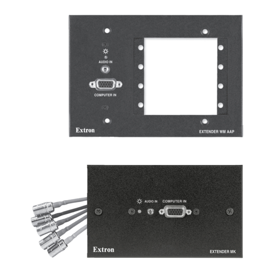
Installation, cont’d Front Panel Features and Cabling AUDIO IN AUDIO IN Faceplate screws — These secure the faceplate to the rest of the line driver. Faceplate dimensions are provided in appendix B of this manual. Do not remove these faceplate screws or the jack screw nuts on either side of the PC Input connector while the line driver is attached to the wall. - Page 19 AUDIO IN COMPUTER IN EXTENDER WM AUDIO IN COMPUTER IN Opening for Architectural Adapter Plates (AAPs) — The Extender WM AAP can have up to four optional adapter plates attached here at one time. The Extender AKM UK can hold up to three optional adapter plates at one time.
- Page 20 Installation, cont’d Other adapter plates must be ordered separately. They also must be attached to the faceplate and cabled before the line driver is installed in the wall or furniture. The screws needed for installing the adapter plates are built into the plates, so no additional screws are needed.
-
Page 21: Top/Rear/Bottom Panel Features And Cabling
Extender MK, Extender AAP, Extender AAP EX, Extender WM AUS, Audio output connector RGB video output connectors Power connector Gain switch Extender AKM UK AAP, and Extender AKM MAAP Extender AKM UK AAP, and Extender AKM MAAP Extender Series • Installation top view... - Page 22 Installation, cont’d Audio output connector — Insert wires into and tighten the screws on this 3.5 mm, 5-pole direct insertion captive screw connector for unbalanced or balanced audio output. Wire the connector as shown in the following illustrations. CAUTION For unbalanced audio, connect the sleeve(s) to the ground contact.
- Page 23 CAUTION For unbalanced audio, connect the sleeve(s) to the ground contact. DO NOT negative (-) contacts. Do not tin the wires! Extender WM is shown here wired for balanced audio output; the circuit board configuration is the same for the Extender WM AAP and the Extender D RGB video output connectors —...
- Page 24 Gain switch — Extender MK, Extender AAP, Extender AAP EX, Extender WM AUS, Extender AKM UK AAP, and Extender AKM MAAP gain switch location (access from the rear) Extender WM and Extender WM AAP gain switch location (access from the side)
- Page 25 To compensate for cable resistance and capacitance, use a small screwdriver to slide this switch to select the level of video gain that yields the sharpest, smear-free picture. Normal — unity gain (no signal boost) Medium — mid-level peaking and gain Maximum —...
-
Page 26: Mounting The Extenders
Installation, cont’d Mounting the Extenders Mounting the Extender AAP or Extender AAP EX into an AAP wall plate or device faceplate The Extender AAP or Extender AAP EX and any other adapter plates must be attached to a device faceplate or AAP wall plate and cabled before the device or wall plate is pretested or installed in a wall or furniture. - Page 27 Two Screws Each Side Front Panel D I O Cable Extron Extender AAP EX Mounting the Extender AAP EX to an HSA faceplate Repeat steps 1, 2, and 3 to mount other AAPs. Cover any openings in the faceplate with blank plates (provided). Be sure to include the AAP connectors as part of the installation pretest before final installation of the faceplate.
-
Page 28: Pre-Installation Testing/Troubleshooting
See “Gain switch” on page 2-12. If the picture appears and is stable, but it has ghosting or blooming, verify that the video input is properly terminated. -
Page 29: Mounting The Extender Wm, Extender Wm Aap, Or Extender Wm Aus To The Wall Box
Mounting the Extender WM, Extender WM AAP, or Extender WM AUS to the wall box Remove power from the line driver by disconnecting the power supply. Place the line driver through the opening in the wall or furniture and into the wall box. Take care not to damage the output cables, which fit behind the line driver at the back of the wall box. -
Page 30: Mounting The Extender D
Installation, cont’d Mounting the Extender D Remove power from the line driver by disconnecting the power supply. Place the Extender D through the opening in the wall or furniture and into the wall box. Take care not to damage the output cables, which fit behind the line driver at the back of the wall box. -
Page 31: Mounting The Extender Mk To The Knockout Box
Mounting the Extender MK to the knockout box Remove power from the line driver by disconnecting the power supply. Place the line driver through the opening in the wall or furniture and into the knockout box. Take care not to damage the cables, which lie next to the line driver at the side of the box. -
Page 32: Application Diagrams
Installation, cont’d Exterder WM.eps Application Diagrams Mini HR Cable Wall Stud D IO Extender WM Projector Extron Extender AKM MAAP Line Driver Extender Series • Installation 2-20 Projector Audio Laptop w/ Audio Mini HR Projector Cable IF T N IT M IN N IT D IO... -
Page 33: Appendix A • Specifications, Part Numbers, And Accessories
Extender Series A ppendix A Specifications, Part Numbers, and Accessories Specifications Ordering Information Accessories... - Page 34 Specifications Video Gain ... 0 dB, 0.6 dB, 1.2 dB, selectable (when Bandwidth... 300 MHz (-3 dB) ID bits are terminated (pins 4 and 11). Video input Number/signal type... 1 VGA–QXGA RGBHV, RGBS, RGsB, Connectors ... (1) 15-pin HD female Nominal level ...
-
Page 35: Audio Input
Sync Input type... RGBHV, RGBS, RGsB, RsGsBs, bi-level Output type... RGBHV, RGBS, RGsB, RsGsBs, bi-level Input level ... 2.0 V to 5.0 Vp-p Output level ... TTL: 5 Vp-p, unterminated Input impedance ... 510 ohms Output impedance ... 75 ohms Max. - Page 36 Specifications, Part Numbers, Accessories, cont’d Nominal level ... -2 dBu, balanced; -10 dBV unbalanced Maximum level (Hi-Z) ... +14 dBu, balanced, at 1% THD+N Maximum level (600 ohm)... +6 dBm, balanced, at 1% THD+N 0 dBu = 0.775 Vrms, 0 dBV = 1 Vrms, 0 dBV ≈ 2 dBu General External power supply ...
- Page 37 Extender WM Faceplate... 4.5" H x 2.8" W x 0.1" D Buffer... 2.7" H x 1.8" W x 0.75" D* Extender WM AUS Faceplate... 3.0" H x 4.7" W x 0.1" D Buffer... 2.75" H* x 1.1" W x 1.2" D Extender WM AAP Faceplate...
- Page 38 Specifications, Part Numbers, Accessories, cont’d Extender D Faceplate... 2.6" H* x 1.3" W x 0.1" D Buffer... 2.7" H x 1.8" W x 0.75" D* Product weight Extender AAP, Extender AAP EX, Extender WM Extender WM AUS... 0.3 lbs (0.1 kg) Extender WM AAP ...
-
Page 39: Mounting Accessories
Ordering Information This section lists part numbers for each Extender and Extender kit. Model Extender AAP (black, white, RAL9010 white) Extender AAP EX Extender WM Extender WM AAP (gray, black, white, RAL9010 white) Extender WM AUS Extender D Extender MK (black &... -
Page 40: Cables
Specifications, Part Numbers, Accessories, cont’d Mud rings/mounting brackets MR 100 – 1-gang modular plastic mud ring (black, white) MR 100D – 1-gang Decora modular plastic mud ring (black) MR 300 – 3-gang modular plastic mud ring (black, white) MR 300D – 3-gang Decora modular plastic mud ring (black) MK 2-gang metal mounting bracket/ mud ring (black, white, RAL9010 white... -
Page 41: Appendix B • Dimensions And Templates
Extender Series A ppendix B Dimensions and Templates Dimensions Templates... -
Page 42: Dimensions
Dimensions Extender AAP and Extender AAP EX dimensions 0.250” (REF) 0.050” (REF) ø 0.250” THRU ø 0.125” THRU 1.400 1.045 0.650 0.345 0.000 Extender Series • Dimensions and Templates The drawings in this section are not full size. Do not scale. All dimensions are given in inches. -
Page 43: Extender Wm Dimensions
Extender WM dimensions 0.000 0.610 1.107 1.550 2.010 2.570 3.392 3.890 4.500 Extender Series • Dimensions and Templates ø 0.156 THRU WITH ø 0.290 X 82° C'SINK (2 PLACES) AUDIO IN COMPUTER IN EXTENDER WM ø 0.125 THRU ø 0.330 THRU WITH ø... -
Page 44: Extender Wm Aap Dimensions
Dimensions and Templates, cont’d Extender WM AAP dimensions Extender Series • Dimensions and Templates 0.449 0.224 6.400 5.650 5.520 5.013 2.780 2.650 2.390 1.388 0.000... -
Page 45: Extender Wm Aus Dimensions
Extender WM AUS dimensions Ø 0.125” THRU Ø 0.250” THRU 3.000” COMPUTER IN AUDIO IN EXTENDER WM AUS 0.000” 2X Ø 0.125” THRU Ø 0.220” X 100° Extender Series • Dimensions and Templates... -
Page 46: Extender Mk Dimensions
Dimensions and Templates, cont’d Extender MK dimensions Extender Series • Dimensions and Templates 0.449” 0.224” 5.700 5.224 4.240 4.017 3.244 2.365 1.958 1.681 1.460 0.474 0.000... -
Page 47: Extender Akm Uk Dimensions
Extender AKM UK dimensions 7.613” 7.428” 6.638” 3.898” 5X 1.643” 0.272” 0.457” Extender Series • Dimensions and Templates 0.449” 0.224” 7.156” 3X 6.768” 3X 3.768” 0.000”... -
Page 48: Extender Akm Maap Dimensions
Dimensions and Templates, cont’d Extender AKM MAAP dimensions 4X R 0.125” 2X R 2X R 0.062 2X 2.350 1.975 1.750 1.250 1.025 2X 0.650 1.675 0.275 0.000 (0.075”) Extender Series • Dimensions and Templates 2X 0.06” X 45° +0.000 3.000 -0.015 2X 2.250”... -
Page 49: Extender D Dimensions
Extender D dimensions 1.290” 2X 0.062” X 45° 0.333” 0.625” 0.223” 0.399” 2X Ø 0.106” THRU 2X 0.111” BOTH SIDES 2X EXTRUSION FOR #6-32 SCREW TAPPING 2X 0.125” (0.223”) Ø 0.132” THRU 2.610” Ø 0.258” THRU 2.005” 1.545” 0.984” 0.905” 0.359 0.000”... -
Page 50: Templates
Dimensions and Templates, cont’d Templates Extender WM template Cut-out Template for the Extron 4.13" 4.50" (10.49 cm) (11.43 cm) Extender Series • Dimensions and Templates B-10 Always check and use the dimensions given in this appendix. Extender WM 2.79" (7.09 cm) 2.24"... -
Page 51: Extender Wm Aap Template
Extender WM AAP template Extender WM AAP Cut-out Template for the Extron 4.5" (11.43 cm) Location of Extender AAP Circuit Board Top Panel 6.4" (16.3 cm) SURFACE CUT-OUT AREA FOR MOUNTING Cut-out line for installing the electrical box. FULL SIZE Extender Series •... -
Page 52: Extender Mk Template
Dimensions and Templates, cont’d Extender MK template Cut-out Template for the Extron 5.70" (14.48 cm) Extender Series • Dimensions and Templates B-12 Extender MK 3.38" (8.56 cm) 1.24" (3.14 cm) 2.94" (7.46 cm) SURFACE CUT-OUT AREA MOUNTING FULL SIZE Panel Location of Extender AAP Circuit Board... -
Page 53: Extender Wm Aus Template
Extender WM AUS template Cut-out Template for the Extron Extender WM AUS 4.65" (11.81 cm) 3.00" (7.62 cm) 1.24" (3.14 cm) 2.94" (7.46 cm) FULL SIZE Extender Series • Dimensions and Templates Top Panel SURFACE CUT-OUT AREA FOR MOUNTING Location of Extender AAP Circuit Board To install... - Page 54 Dimensions and Templates, cont’d Extender Series • Dimensions and Templates B-14...
- Page 55 Extron Electronics warrants this product against defects in materials and workmanship for a period of three years from the date of purchase. In the event of malfunction during the warranty period attributable directly to faulty workmanship and/or materials, Extron Electronics will, at its option, repair or replace said products or components, to whatever extent it shall deem necessary to restore said product to proper operating condition, provided that it is returned within the warranty period, with proof of purchase and description of malfunction to:...
- Page 56 Extron Electronics, USA 1230 South Lewis Street Anaheim, CA 92805 800.633.9876 714.491.1500 FAX 714.491.1517 www.extron.com Extron Electronics, Europe Extron Electronics, Asia Beeldschermweg 6C 135 Joo Seng Rd. #04-01 3821 AH Amersfoort, The Netherlands PM Industrial Bldg., Singapore 368363 +800.3987.6673 +31.33.453.4040 +800.7339.8766 +65.6383.4400 FAX +31.33.453.4050 FAX +65.6383.4664...
Need help?
Do you have a question about the VGAUXGA Line Drivers With Audio Extender Series and is the answer not in the manual?
Questions and answers