Extron electronics DTP HDMI 230 Setup Manual
Digital video extender
Hide thumbs
Also See for DTP HDMI 230:
- Setup manual (2 pages) ,
- User manual (20 pages) ,
- Setup manual (2 pages)
Advertisement
Table of Contents
DTP HDMI 230 • Setup Guide
This guide provides quick start instructions for an experienced installer to set up and operate the
Extron DTP HDMI 230 digital video extender. The DTP HDMI 230 transmitter and receiver pair can
extend an HDCP-compliant HDMI signal up to 230 feet (70 m).
Installation
Step 1 — Mounting
Turn off or disconnect all equipment power sources and mount the Tx and Rx units as required.
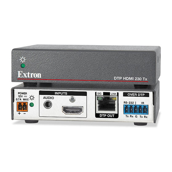
DTP HDMI 230 Tx Rear Panel
INPUTS
POWER
AUDIO
12V
0.7A MAX
7
2
Step 2 — Connections
a
HDMI Input connector (Tx) — Connect an HDMI
cable between this port and the HDMI output port of
the digital video source.
NOTE: See the
"LockIt™ Lacing
securely fasten the input HDMI connector to the transmitter.
b
Audio input (Tx) — Connect an unbalanced stereo audio source to this 3.5 mm mini
stereo jack for an analog audio input.
c
RS-232 and IR connectors — To pass serial or infrared data or control signals, such as
serial control of a projector, connect the master device to the transmitter and the slave
device to the receiver via the RS-232 and IR captive screw connectors on both units.
d
DTP RJ-45 connectors — Connect transmitter DTP Out to receiver DTP In.
Extron recommends that you terminate both cable ends in accordance with the
following specifications, at a minimum:
TIA/EIA T 568 B
z
24 AWG, solid conductor
z
ATTENTION: Do not connect these devices to a computer data or telecommunications
network.
Signal LED — Lights when the unit is receiving a TMDS clock signal on the HDMI input (transmitter) or
any valid signal on the DTP In connector (receiver).
Link LED — Lights when a valid link is established between the units on the DTP cable.
e
HDMI Output connector (Rx) — Connect a display with an HDMI input for display of the
transmitted direct digital image.
NOTE: See the
"LockIt™ Lacing
securely fasten the output HDMI connector to the receiver.
f
Audio Output connector (Rx) — Connect a balanced or unbalanced stereo or mono audio
device to the receiver via the Audio captive screw connector. See the drawing below.
Do not tin the wires!
ATTENTION:
Connect the sleeves to the ground contact. DO NOT connect the sleeves to the negative (-) contacts.
SIG
LINK
OVER DTP
RS-232
Tx Rx
DTP OUT
1
4
Brackets"on the back of this guide for to
z
Brackets"on the back of this guide for to
No Ground Here
Tip
Sleeves
Tip
No Ground Here
Unbalanced Stereo Output
DTP HDMI 230 Rx Rear Panel
POWER
12V
IR
0.7A MAX
G
Tx Rx
3
7
INPUTS
AUDIO
CAT 6A, shielded
Tip
Ring
Sleeves
Tip
Ring
Balanced Stereo Output
SIG
LINK
DTP IN
4
5
Front Panel
OVER DTP
RS-232
IR
Tx Rx
G
Tx Rx
3
Connected RS-232
Tx/Rx
and IR Device Pins
Pins
Pins:
12345678
TP Wires
OUTPUTS
AUDIO
L
R
6
DTP HDMI 230 Rx
Transmit pin on connected unit
Receive pin on connected unit
Ground
Transmit pin on connected unit
Receive pin on connected unit
TIA/EIA T
568 B
Pin
Wire color
1
White-orange
2
Orange
3
White-green
4
Blue
5
White-blue
6
Green
7
White-brown
8
Brown
OUTPUTS
AUDIO
L
R
Advertisement
Table of Contents

Related Manuals for Extron electronics DTP HDMI 230


Summary of Contents for Extron electronics DTP HDMI 230
- Page 1 This guide provides quick start instructions for an experienced installer to set up and operate the Extron DTP HDMI 230 digital video extender. The DTP HDMI 230 transmitter and receiver pair can extend an HDCP-compliant HDMI signal up to 230 feet (70 m).
- Page 2 DTP HDMI 230 • Setup Guide (Continued) Power connector — Connect an IEC power cord between the included 12 VDC power supply and a 100-240 VAC, 50-60 Hz source. Connect the power supply to Smooth Ridges either unit as shown at right. Use the included tie-wrap to strap the cord to the Captive captive screw connector.
Need help?
Do you have a question about the DTP HDMI 230 and is the answer not in the manual?
Questions and answers