Advertisement
eLink 100 • Setup Guide
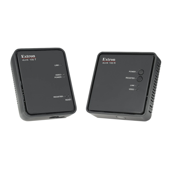
The Extron eLink 100 T (transmitter) and eLink 100 R (receiver) units wirelessly extend HDMI signals up to 100 feet (30 m) with
a clear line-of-sight. Up to four receivers can be linked to a single transmitter, allowing the HDMI video from one source to be
output on multiple displays simultaneously.
This guide provides instructions for setting up and operating the eLink 100 transmitter and receiver (sold separately).
ATTENTION:
•
This equipment complies with FCC radiation exposure limits set forth for an uncontrolled environment. This equipment
should be installed and operated with minimum distance 20 cm (7.9 inches) between the radiator and your body.
•
Cet équipement est conforme aux limites de radiation de la FCC établies pour un environnement non géré. Il doit être
installé et contrôlé à une distance minimale de 20 cm (7,9 pouces) entre le radiateur et votre corps.
Mounting
The eLink 100 extenders can be mounted to a wall or a furniture surface, if needed. See the eLink 100 User Guide (available
online at www.extron.com) for mounting instructions.
Cabling
Transmitter Connections
A
HDMI In connector — Connect an HDMI
cable between this port and the HDMI
output port of the video source device.
IR Out connector — (Optional) Connect
B
the tip-ring-sleeve end of the provided
IR emitter to this IR Out connector. Use
the included adhesive tape to attach the
head of the IR emitter directly over the IR
receiver window of the source device.
IR remote signals are passed from the receiver to the IR Out connector on the transmitter. This allows the user to point the
remote toward the receiver (by the display) instead of the source device, should the source device be in a different location.
Power input connector — Plug the external 5 VDC power supply into this 5 V jack to power the transmitter.
C
NOTES:
•
Each eLink 100 power supply kit contains a set of four plugs for use in different outlet types. See the eLink 100
User Guide for instructions on replacing the plug, if needed.
•
The USB mini-B port to the right of this connector is reserved for use by Extron service personnel.
Receiver Connections
IR sensor — Receives IR commands
A
from the included IR remote control
unit and the IR remote of the source
device.
USB Power connector — Connect
B
the USB end of the provided 5 V
jack-to-USB adapter to this USB
mini-B connector (see image below).
Connect the other end of the adapter to the provided 5 VDC power supply.
IMPORTANT:
Refer to www.extron.com for the complete
user guide, installation instructions, and
specifications before connecting the
product to the power source.
HDMI IN
IR OUT
DC Connector
on Power Supply
To Power Supply
POWER
5V
1.5A MAX
B B
HDMI
5V
1.5A MAX
HDMI OUT
POWER
Back Panel
To USB Power
Connector on
Receiver
SERVICE
Advertisement
Table of Contents

Related Manuals for Extron electronics eLink 100


Summary of Contents for Extron electronics eLink 100
-
Page 1: Transmitter Connections
100 • Setup Guide The Extron eLink 100 T (transmitter) and eLink 100 R (receiver) units wirelessly extend HDMI signals up to 100 feet (30 m) with a clear line-of-sight. Up to four receivers can be linked to a single transmitter, allowing the HDMI video from one source to be output on multiple displays simultaneously. -
Page 2: Transmitter Unit
After registration is performed at the initial setup, the transmitter and receiver connect automatically when booted. The units can be registered using the eLink 100 remote control (see the eLink 100 User Guide for instructions) or using the register buttons on the eLink 100 units (see the instructions below).
Need help?
Do you have a question about the eLink 100 and is the answer not in the manual?
Questions and answers