Table of Contents
Advertisement
Advertisement
Table of Contents

Subscribe to Our Youtube Channel
Related Manuals for Paramount Fitness Clear 03


Summary of Contents for Paramount Fitness Clear 03
-
Page 1: Installation Manual
WATER PURIFYING SYSTEM INSTALLATION MANUAL MADE IN USA 004-027-8780-00 REV110711 US Patent 7,837,951 295 East Corporate Place • Suite 100 • Chandler, AZ 85225 Toll Free: 1.800 . 621.5886 • Phone: 480.893.7607 • Fax: 480.753.3397 Paramount@1Paramount.com • www.1Paramount.com... -
Page 2: Safety Instructions
SAFETY INSTRUCTIONS IMPORTANT SAFETY INSTRUCTIONS: READ COMPLETELY BEFORE PROCEEDING WITH INSTALLATION. SAVE THESE INSTRUCTIONS When using this electrical equipment, basic safety precautions should always be followed, including the following: CAUTION: READ AND FOLLOW ALL INSTRUCTIONS WARNING: • Follow all applicable electrical codes. •... - Page 3 SAFETY INSTRUCTIONS (CONT.) shock, connect the local common bond grid in the area of the pool or spa to this terminal with an insulated or bare copper conductor not smaller than 6 AWG. WARNING: • ALWAYS wear safety glasses when using power equipment during the installation process.
-
Page 4: What Is Ozone And How Does It Work
WHAT IS OZONE AND HOW DOES IT WORK • Ozone is created from oxygen using a simple yet powerful system of UV bulbs, to be used as a pure shock (oxidizer) for the swimming pool. ® • Ozone is injected into the pool water using the Clear O3 suction injection system, where the ozone enriched air is mixed with the water going into the pool circulation pump. -
Page 5: Selecting Location & Mounting Unit
TO COMPLETE INSTALLATION YOU WILL NEED THE FOL- LOWING ITEMS (NOT INCLUDED) (1) Six (6) feet 1/2” non-metallic conduit outdoor rated. (1) 1/2" conduit compression fitting. SELECTING LOCATION & MOUNTING UNIT 1. Select a location on a wall near the pool equipment or insert posts into the ®... - Page 6 SELECTING LOCATION & MOUNTING UNIT 6. Mark the location for the two bottom brackets. ( Fig. 2 ) ® Remove the Clear O3 from the wall and install the wall anchors. ® 8. Place the Clear O3 unit back on the screws and line up the two lower brackets with the wall anchors.
-
Page 7: Making Electrical Connections
MAKING ELECTRICAL CONNECTIONS 1. A licensed electrician should make all electrical connections. Make sure the unit is grounded by connecting to the pool equipments bond wire to comply with local electrical codes. See wiring diagram ( Fig. 4 ). 2. Turn off power to the filtration system pump at the circuit breaker. 3. - Page 8 MAKING ELECTRICAL CONNECTIONS (CONT.) Fig. 5B Fig. 5A Ground Lug 4. Connect green ground wire to the time clock ground bar ( Fig. 6A ) . The ® unit is set to 240VAC to be connected to the load side ( Fig. Clear O3 6B ) of the filtration pump time clock.
- Page 9 MAKING ELECTRICAL CONNECTIONS (CONT.) ® The Clear O3 should Fig. 8 run with the filter pump as the filter pump creates the air draw through the unit needed to create ozone. Do not ® set the Clear O3 to run Ground Lug when the filter pump is off and not pulling air...
-
Page 10: Making Plumbing Connections
MAKING PLUMBING CONNECTIONS 1. Turn off power to the filtration Fig. 10 system pump at the circuit breaker. 2. Pump strainer pot installation: ( Fig. 10 ) 2.1 Check pump elevation above water level. Refer to (Chart 1) for proper check Chart 1 Pump Elevation Above Check Valve... - Page 11 MAKING PLUMBING CONNECTIONS (CONT.) Fig. 12 2.4 Install the combination needle valve flow meter on the bottom of the Clear ® unit. ( Fig. 12 ) 2.5 Install 3/8 OD x 1/4 ID tubing to compression end of check valve. ( Fig. Fig.
- Page 12 MAKING PLUMBING CONNECTIONS (CONT.) 4. OPTIONAL SUBMERGED EQUIPMENT INSTALLATION (Fig. 14B) To complete this installation option you will need a two way valve not included. 4.1 Install the two way valve on the inlet pipe to the pump suction. (before the standpipe if installed) 4.2 Make all other connections before the two way valve.
- Page 13 MAKING PLUMBING CONNECTIONS (CONT.) 5. Lay the 3/8 tubing along Fig. 15 desired route to the compression fitting on the combination needle valve ® flow meter on the Clear O3 unit. 6. Connect the tubing to the compression fitting. ( Fig. 15 ) 7.
-
Page 14: Optional Submerged Equipment Install
OPTIONAL SUBMERGED EQUIPMENT INSTALL. New Installation using Paramount venturi installation kit. Fig. 17 TO COMPLETE THIS INSTALLATION YOU WILL NEED THE FOLLOWING ITEMS (NOT INCLUDED) (2) 2” X 2” X ¾” SLIP TEE (1) ¾” X ¾” UNION BALL VALVE (2) 2” VALVES ¾” FITTINGS AND PIPE (2) ¾”... - Page 15 OPTIONAL SUBMERGED EQUIP. INSTALL.(CONT.) Install the 3/8” OD x ¼ ID tubing on Fig. 19 the barbed end of the venturi, with the check valve installed in-line. Note the correct direction of flow through the check valve. (Fig. 19A & 19B) Connect the tubing to the compression fitting.
-
Page 16: Setting Air Flow
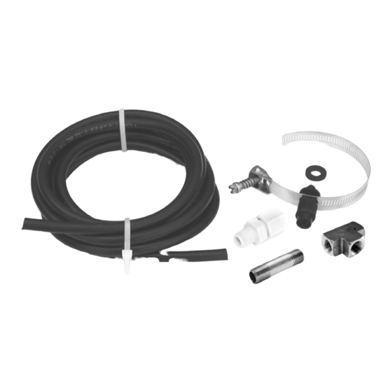
( Fig. 22 ) IMPORTANT NOTES REGARDING THE FLOW METER: ® 1. IF THE PUMP THAT THE CLEAR 03 UNIT IS INSTALLED ON IS A PUMP RUNNING A PARAMOUNT IN-FLOOR SYSTEM, lock the water valve on pause when the valve is switching ports and therefore at it’s maximum flow (the pause... - Page 17 EXTERNAL SAFETY AIR BLEED KIT INSTRUCTIONS (OPTIONAL) Sometimes the internal Fig. 23 air bleed on the filter is not sufficient to handle the extra air in the system with an ozonator installed. An External Safety Air Bleed Kit (006-402- 3872-00) ( Fig. 23 ) for in-ground swimming pools is available to remove excess air from...
-
Page 18: Bulb Replacement
EXTERNAL SAFETY AIR BLEED KIT INSTRUCTIONS (OPTIONAL) (CONT.) 6. Install the tee assembly by threading into the hole where you removed the pressure gauge ( Fig. 24 Pg. 17 ) . 7. Insert one end of the tubing into the compression fitting ( Fig. 24 Pg. 17 ) . 8. - Page 19 BULB REPLACEMENT (CONT.) 1. Turn the power off to Fig. 25 filtration system pump at circuit breaker. 2. Remove three screws in left end side cap labeled “electrical connections”. ( Fig. 25 ) 3. Remove side cap. ( Fig. 26 ) 4.
- Page 20 BULB REPLACEMENT (CONT.) 5. Remove plug from Fig. 28 light bulb. ( Fig. 28 ) 6. Pull light bulb free ® from Clear O3 unit. ( Fig. 29 ) Make sure gasket is in place on replacement light bulb. 8. Align with key and slide into hole until Fig.
-
Page 21: Troubleshooting And Service
TROUBLESHOOTING & SERVICE ISSUE SOLUTION 1. No air bubbles Clean filter then adjust entering system or pool airflow needle valve. 2. Filter empties and Replace check valve pump loses prime fitting at strainer pot. 3. Light bulb does not light Check power to Clear ®... - Page 22 CONVERTING BALLAST VOLTAGE TO ALTERNATE SETTING (CONT.) Fig. 33 While holding the bulb, wiggle the plug to loosen from the bulb and pull it free from light bulb. ( Fig. 33 ) Pull the light bulb from the unit. With a Phillips screwdriver, remove the two (2) screws inside the electrical Fig.
- Page 23 CONVERTING BALLAST VOLTAGE TO ALTERNATE SETTING (CONT.) the ballast and a nut Fig. 36 holding the two ground wires in place. ( Fig. 35 ) 10. On the back of the unit nearest the open end, remove the flatheaded screw with a Phillips screwdriver while holding the lock nut on the inside of the cavity with pliers.
- Page 24 CLEAR 03® WATER PURIFYING SYSTEM For technical assistance call 1.800.621.5886 or contact your regional representative...
- Page 25 CLEAR 03® WATER PURIFYING SYSTEM Item Part Number Description SINGLE UNIT ® 004-402-3880-00 Clear O3 Single Assembly 005-402-3834-00 Lamp 005-402-3820-00 Mounting Brackets (4Pk) Ground Lug 005-402-1384-00 Conduit Compression Fitting 1/2" Wiring Harness 3-Wire 12 Gauge X 6ft 005-402-3361-00 Tubing with Check Valve Pump Mount, &...
-
Page 26: Warranty Information
WARRANTY INFORMATION... -
Page 27: Warranty Registration
WARRANTY REGISTRATION See Warranty Certificate on page 26 POOL OWNER INFORMATION Name: Address: City: State: Zip Code: Telephone: Fax: E-mail: Pool Start-Up Date Purchased: Type of Pool (check one): Concrete Vinyl Fiberglass Type of Pool System (check one): PCC 2000 Pool Valet Cyclean Vanquish... - Page 28 Fold Here Place Stamp Here Paramount Pool & Spa Systems 295 East Corporate Place, Suite 100 Chandler, AZ 85225 Staple Here...
Need help?
Do you have a question about the Clear 03 and is the answer not in the manual?
Questions and answers