
Related Manuals for Lynxmotion AL5D-PLTW


Summary of Contents for Lynxmotion AL5D-PLTW
- Page 1 RobotShop Product Code: RB-Lyn-814 Lynxmotion SKU: AL5D-PLTW Guide release date / version V1.2 March 2018 RobotShop Inc. 305-18005 Lapointe Mirabel, Quebec, Canada J7J0G2...
-
Page 2: Table Of Contents
About Lynxmotion / RobotShop AL5D Robot Arm What’s Included Part Codes Tools Required RC Servo Technology Angle Torque Operation Assembly A. Base B. Arm Assembly C. Servo Installation D. Software / Servo Setup E. Cleanup & Mounting Important Notes Warranty Information... -
Page 3: About
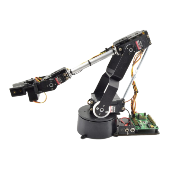
AL5D Robot Arm The AL5D - PLTW arm is part of Lynxmotion’s series of AL5 robot arms (AL5A, AL5B and AL5D; the AL5C was discontinued). The AL5D robotic arm delivers fast, accurate, and repeatable movement. -
Page 4: What's Included
Lynxmotion or on YouTube. We suggest using this guide only. If you purchase the AL5D-PLTW (RB-Lyn-814) arm, it will include everything mentioned below. The arm does not require any additional parts for use with the Project Lead The Way curriculum, though additional accessories are available separately. -
Page 5: Part Codes
Part Codes The following diagram illustrates the parts (Lynxmotion codes) used to make the standard AL5D arm (without the additional parts for PLTW). Standard AL5D Robot Arm (V1) w. Old SSC-32 Medium duty wrist rotate upgrade RobotShop Inc. 305-18005 Lapointe, Mirabel, Quebec, Canada, J7J0G2... -
Page 6: Tools Required
Note: We include a variety of additional parts which you will not use in the construction of the arm. This is because the AL5D-PLTW is nevertheless part of a modular building system, and parts / kits which make up the arm are also used in other kits. -
Page 7: Angle
RC Servo Technology The AL5D uses Hitec RC servo motor actuators at each joint. These servos are classically used in the RC hobby industry to control ailerons and landing gear on airplanes, rack and pinion steering on RC cars and come in a variety of sizes and torque ratings. Given their popularity, easy of use, low price and absolute positioning, RC servos were adapted for use in animatronics and robotics. -
Page 8: Assembly
Assembly Note that there is also an online assembly guide from Lynxmotion for the AL5D (which uses photos), as well as a YouTube video, however this manual is an updated version, so we suggest using ONLY this guide for the assembly steps. - Page 9 Step A3 (optional): Lay a piece of 400 grit sandpaper (not included) on a flat surface and carefully turn the base assembly from step 2 upside down. Press the base against the sandpaper in small circles on it to remove any imperfections on the beads. Step A4 (optional): The image below shows the circle pattern on the sandpaper and the inset shows the bearings after any imperfections have been removed.
- Page 10 Step A5 : The Hitec 485HB servo is shipped with its white plastic horn centered. If the horn is rotated by accident, ensure it lines up like the image below. It should rotate 90 degrees CCW and 90 degrees CW. Unscrew the black screw holding the horn in place and KEEP IT for step A9).
- Page 11 Step A7 : Attach the large ASB-204 multipurpose bracket onto the base top using four 2-56 x .250" phillips head machine screws and four 2-56 nuts as shown. Note, the bracket and hardware are included in the arm kit, not the base kit. Ensure the orientation looks like the image below.
- Page 12 Step A9 : Install the base top using the horn screw from step A5. The hole pattern of the top plate should line up with one row of holes pointing to the servo wire hole at the rear, and all of the lines pointing between the mounting tabs.
- Page 13 Option 2: Lynxmotion Base Electronics Carrier Kit OPTION 1 (AL5 to VEX plate) Step A11 : Screw four 4-40 x 1” long standoffs included with the Lynxmotion to VEX Adapter to the plate using four 4-40 x ⅜” long hex screws.
- Page 14 Step A12 : Use two 4-40 x ⅜” hex screws and two 4-40 x ¼” lock nuts to fix the RobotShop Inc. 305-18005 Lapointe, Mirabel, Quebec, Canada, J7J0G2...
- Page 15 RobotShop Inc. 305-18005 Lapointe, Mirabel, Quebec, Canada, J7J0G2...
- Page 16 Step A13 : Install the power plug wiring harness as shown (servo controller greyed out). To do so, you need to remove the nuts and spacers which come installed on both the switch and barrel connector. You can use a tie wrap or tape to hold the wires in place. The SSC-32U only needs the one wiring harness.
- Page 17 Step A14 : Install the SSC-32 (shown) or the SSC-32U using four more 1/4" x 3/8" hex socket screws. Do not make the electrical connections yet. The base rotate is shown just for reference so you know where it will be placed later. RobotShop Inc.
- Page 18 Step A15 : Twist each end of the multi-strand wires to ensure there are no loose wires which can cause a short circuit. This will also make the multi-strand wires easier to insert into the screw terminal. Unscrew the VS1+ and VS1- terminals so the wires can be inserted. This means rotating the screw so that the inner metal touches the bottom of the plastic (see visually).
- Page 19 Note that the lexan plate can be in either orientation - whichever works best for you. The orientation below is “standard”. Note: If you have purchased the Lynxmotion Base Rotate / Heavy Duty Base to VEX Adapter, you will not need this plate and must use that adapter plate instead for these steps.
- Page 20 Step A12 : Install the power switch bracket using two 4-40 x 3/8" hex socket screws and two 4-40 nylon insert lock nuts, ensuring the bracket is on the same side as the standoffs. The bracket can be on the left or the right side - whichever works best for your application. RobotShop Inc.
- Page 21 Step A13 : Install the power plug wiring harness as shown (servo controller greyed out). To do so, you need to remove the nuts and spacers which come installed on both the switch and barrel connector. You can use a tie wrap or tape to hold the wires in place. The SSC-32U only needs the one wiring harness.
- Page 22 Step A14 : Install the SSC-32 (shown) or the SSC-32U using four more 1/4" hex socket screws. Do not make the electrical connections yet. Step A15 : Twist each end of the multi-strand wires to ensure there are no loose wires which can cause a short circuit.
- Page 23 If you find it difficult to insert all of the wire strands, or they are too “messy”, use wire cutters (or sharp scissors) to remove some of the shielding at the end (~0.5cm) and then carefully cut some of the wire, ensuring all of the wires are straight and compact. NOTE: Once again, ensure no wires touch between the red and black leads at the screw terminals! RobotShop Inc.
-
Page 24: Arm Assembly
B. Arm Assembly Step B1 : Connect the a large "C" bracket (ASB-203) and an 805 "C" bracket (ASB-205) together as shown using two 2-56 x 1/4" screws and two 2-56 nuts. RobotShop Inc. 305-18005 Lapointe, Mirabel, Quebec, Canada, J7J0G2... - Page 25 Step B2 : The dampening panels / discs used in this step are laser cut lexan pieces (two circles). They have a protective covering that needs to be removed from both sides before assembly. You can also break the two circles apart. The yellow powder is residue from the laser cutting process.
- Page 26 The panels with the larger holes are on the outside of the bracket. RobotShop Inc. 305-18005 Lapointe, Mirabel, Quebec, Canada, J7J0G2...
- Page 27 Step B3 : Insert a 4-40 x 0.5" Phillips head screw through the hole in the multi-purpose bracket as shown. Secure with a steel nut. Ensure the right screw is used. RobotShop Inc. 305-18005 Lapointe, Mirabel, Quebec, Canada, J7J0G2...
- Page 28 RobotShop Inc. 305-18005 Lapointe, Mirabel, Quebec, Canada, J7J0G2...
- Page 29 Step B4 : Slide the large "C" bracket end of the bracket assembly over the screw as shown, and secure with a 4-40 lock nut. The amount of friction can be adjusted by tightening or loosening the lock nut. Start with the nut loose, and if the arm seems to wobble a bit, you can tighten this joint to correct the wobble.
- Page 30 Step B6 : Attach the tubing connector hub to the short side of the "L" bracket using two 2-56 x .250 screws and 2-56 nuts. Orientation of the screws, tubing connector and bracket are important ; the hole in the tubing connector should be as shown, so the tube lines up as in figure 7.
- Page 31 Step B7 : Connect the hub sub-assemblies from step B6 to the 4.50" tube using two 4-40 x .250" screws. Tighten these screws well as they have a tendency to want to unscrew themselves during operation. RobotShop Inc. 305-18005 Lapointe, Mirabel, Quebec, Canada, J7J0G2...
- Page 32 Step B8 : Attach one end of the tubing structure to a Standard Multi-Purpose bracket and the other end to a Large Multi-Purpose bracket as shown in the image, using two 2-56 x .250 screws and two 2-56 nuts for each bracket. Orientation is important, as well as which holes are used for the screws, so follow the image below.
- Page 33 Step B9 : Insert a 4-40 x 0.5" long Phillips head screw through the hole in the large multi-purpose bracket in the location shown. Secure with a steel nut. This creates the forearm subassembly. RobotShop Inc. 305-18005 Lapointe, Mirabel, Quebec, Canada, J7J0G2...
- Page 34 Step B10 : (Similar to step 4) Slide the screw on the forearm subassembly through the dampening discs, and secure with a nylon insert lock nut. The amount of friction can be adjusted by tightening or loosening the lock nut. Start with the nut loose, and if the arm seems to wobble a bit, you can tighten this joint to correct the wobble.
-
Page 35: Servo Installation
C. Servo Installation There are four sizes of servo motors included with the arm. The Hitec 805BB is the largest, followed by the 755HB, and the 422, 485 and 645 all look essentially the same.The smallest is the 255MG used in the wrist rotate upgrade. Step C1 : Remove (and keep) the screw holding down the black horn which comes fixed to the 755 servo. - Page 36 Step C2 : The white horn which comes preinstalled on the Hitec 225 and 422 servos will not be needed... HOWEVER, the output spline needs to remain zeroed, as shown in the image to the left. Remove (and keep) the screw holding the horn in place. Ensuring the horn is in exactly this orientation, pull it up and off the servo.
- Page 37 Step C3 : Install the Hitec 805 in the shoulder, starting with one M3 x 9mm screw, M3 washer and M3 nut which are part of the servo hardware attachment bag. Note that the included spring should be placed between the washer and the servo and oriented vertically as shown. Optional : pass the wire between the servo and the lower bracket so it exits at the rear.
- Page 38 Step C4 : Install the remaining three M3 screws, nuts and washers as shown. RobotShop Inc. 305-18005 Lapointe, Mirabel, Quebec, Canada, J7J0G2...
- Page 39 Step C5 : Install the 755 servo in the shoulder using the M3 screw, nut, spring and washer, placing the spring between the washer and the servo. Do not connect the two springs together yet (easier to manipulate the arm). Optional: pass the wire between the servo and the bracket so it exits at the rear.
- Page 40 Step C6 : Install the other three M3 screws, washers and nuts.One is more hidden and harder to install, but take your time. RobotShop Inc. 305-18005 Lapointe, Mirabel, Quebec, Canada, J7J0G2...
- Page 41 Step C7 : Install the 645 servo in the wrist using four M3 screws, M3 washers and M3 nuts (the servo hardware mounting kit). Optional: Pass the servo wire between the sero and the multipurpose bracket so it exits at the rear. RobotShop Inc.
- Page 42 Step C8 : (New sub-assembly) Install the 225 servo in the medium duty wrist rotate bracket using four M3 screws, nuts and washers. RobotShop Inc. 305-18005 Lapointe, Mirabel, Quebec, Canada, J7J0G2...
- Page 43 Step C9 : Slide the medium duty wrist rotate sub-assembly over the bearing in the wrist and then over the white servo horn. Orientation of the wrist rotation servo servo should be as the image below (if not, the wrist rotation will be reversed). So far, none of the horns have been attached to the brackets.
- Page 44 Step C10 : At this point the wires from the servos should be loose. Connect the following extension cables, ensuring the order of the colors stay the same from servo to extension (always yellow to yellow, red to red, black to black). ●...
-
Page 45: Software / Servo Setup
D. Software / Servo Setup Step D1 : Connect the servos to the SSC-32U and be sure to connect the yellow signal / pulse wire towards the inside of the board, and the black / GND wire to the outside as shown. ●... - Page 46 Step D2 : Re-verify the green VS1 terminal on the SSC-32U and ensure that there are no loose wires between the red and black which can cause a short circuit. Connect the power supply to the wall and then to the barrel connector. Turn the switch to ON. When the board is first turned on, LED A (green) and LED B (red) should both light up, indicating that the baud rate is set to 9600.
- Page 47 Step D5 : At the bottom right of the screen: 1. Set the Baud rate to 9600 2. Select the COM port associated with the SSC-32, or choose “AUTO” 3. The green FOUND light on screen should become solid. 4. The servos might rotate quickly if they are not centered. Step D6 : Activate servos 4 and 5 within the software by pressing each checkbox.
- Page 48 There are two gripper ways to mount the gripper (steps 7 and 8): Option 1: Standard Option 2: Inverted (to allow the gripper to pick up objects parallel to the surface) OPTION 1 Step D7 : With the servos all centered (1500) and powered, you can now connect the horns to the brackets, starting with the gripper.
- Page 49 Step D8 : Position the gripper to halfway open (0.65 inches between fingers). IMPORTANT NOTE: The direction which the horn rotates to open and close the gripper is very important. The “arms” should close around the central shaft to close the gripper. In the software, move the slider associated with servo 4 to see the open and close.
- Page 50 OPTION 2 Step D7 : With the servos all centered (1500) and powered, you can now connect the horns to the brackets, starting with the gripper. Use the same screw which you had removed from the 225MG servo. Align the gripper as shown, and press it onto the 225 servo spline. The screw is secured through the hole in the gripper.
- Page 51 Step D8 : Position the gripper to halfway open (0.65 inches between fingers). IMPORTANT NOTE: The direction which the horn rotates to open and close the gripper is very important. The “arms” should close around the central shaft to close the gripper. In the software, move the slider associated with servo 4 to see the open and close.
- Page 52 The following steps will show option 1 (standard) Step D9 : With the wrist servo still powered, align the bracket parallel to the elbow-wrist tube as shown. Two holes in the 645 servo’s horn should align with two holes in the bracket. Use two #2 x ¼”...
- Page 53 Step D10 : With the 755 elbow servo still powered and zeroed, align the bracket perpendicular to the elbow-wrist tube as shown. Two holes in the 755 servo’s horn should align with two holes in the bracket. Use two #2 x ¼” tapping screws to fix it in place. Move the slider corresponding to servo 2 to see the range of motion.
- Page 54 Step D11 : With the 805 still powered and centered, use two #4 x ⅜” steel Phillips head tapping screws to fix the bracket to the servo horn. RobotShop Inc. 305-18005 Lapointe, Mirabel, Quebec, Canada, J7J0G2...
-
Page 55: Cleanup & Mounting
E. Cleanup & Mounting RobotShop Inc. 305-18005 Lapointe, Mirabel, Quebec, Canada, J7J0G2... - Page 56 Step E1 : Cut power to the arm via the on/off switch, close the software and disconnect the USB cable and power cable. The next step is to rout the wires cleanly, ensuring that all joints have their full range of motion. RobotShop Inc.
- Page 57 Step E2 : The arm needs to be fixed to a base or else it will fall over. We suggest a flat piece of wood at least 12” x 12”. The electronics carrier is meant to be placed on the same side as the “back”...
- Page 58 Step E4 : Repeat for the elbow joint, ensuring that the wires do not prevent it from rotating over the full range. One tie wrap can be used to secure the cables to the bracket. Clean wire wrapping is an art, so before fixing the tie wraps permanently in place, try a few different ways to route the wires, and always ensure each joint can rotate its full range.
- Page 59 Step E6 : Connect power to the arm, and connect the SSC-32U to the computer via USB. You can turn the arm ON. Position it in a semi retracted position similar to the image below: RobotShop Inc. 305-18005 Lapointe, Mirabel, Quebec, Canada, J7J0G2...
- Page 60 RobotShop Inc. 305-18005 Lapointe, Mirabel, Quebec, Canada, J7J0G2...
- Page 61 Step E7 : Install FlowArm PLTW from the included CD. The license number should be included on the printed invoice. If you have any issues with locating the license, please contact supportcenter@robotshop.com When you start the program, depending on the settings, the arm may or may not snap into position.
- Page 62 Step E9 : Press the “Calibrate” button towards the bottom left of the window to enter calibration mode. The arm will move to a new position: All servos should be at 1500 (centered). If a joint seems slightly off by a few degrees, use the calibration knobs which have appeared on screen.
- Page 63 If a joint seems to be very far off the desired position, this means the bracket was not connected properly. Unscrew the center screw holding the horn in place and gently flex the bracket (with the horn still attached) away from the servo. Reposition the assembly to the desired position and gently press the horn back onto the servo and replace the screw.
-
Page 64: Warranty Information
Warranty Information The warranty on the Lynxmotion AL5D - PLTW arm is one year from the date of receipt under normal use. RobotShop Inc. 305-18005 Lapointe, Mirabel, Quebec, Canada, J7J0G2...
Need help?
Do you have a question about the AL5D-PLTW and is the answer not in the manual?
Questions and answers