Table of Contents
Advertisement
Quick Links
Symmetric Quadruped Robot Kit Assembly
Instructions Rev. 1.
Safety first! Wear eye protection and never
touch a powered robot!
The purpose of this guide is to construct the
chassis, attach the legs, and install the
electronics. Both the top and bottom body plates
are identical. This guide shows the PS2 receiver
and plate which are purchased separately from
the kit.
Step 1. Build the Lower Body.
Both the top plate and bottom plate are identical.
Place the small black rivet through the 9V metal
clip and push down through one of the two inner
holes as shown. It does not matter which side.
This will become the bottom plate.
1 x
Step 2.
Use six 4-40 x 1/4" hex socket screws to attach
the long aluminum spacers to the bottom body
plate.
6 x
6 x
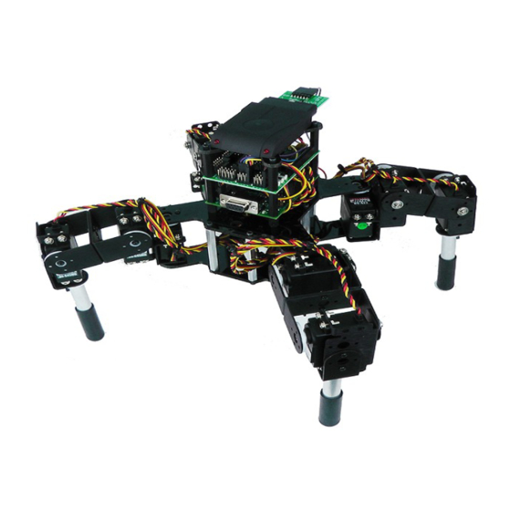
Image of completed Robot.
(Shown with optional PS2 receiver and mount)
Figure 1.
Figure 2.
Advertisement
Table of Contents

Related Manuals for Lynxmotion Symmetric Quadruped Robot Kit


Summary of Contents for Lynxmotion Symmetric Quadruped Robot Kit
- Page 1 Symmetric Quadruped Robot Kit Assembly Instructions Rev. 1. Safety first! Wear eye protection and never touch a powered robot! The purpose of this guide is to construct the chassis, attach the legs, and install the electronics. Both the top and bottom body plates are identical.
- Page 2 Step 3. Use the second (top) plate for this step. Use four 4-40 x 1/4" hex socket screws to attach the 1/4" long M/F plastic spacers to the plate. If you only plan to use the SSC-32 and Bluetooth, use a F/F spacer instead of the M/F spacer.
- Page 3 Step 6. Here are some general guidelines when inserting the wires into the SSC-32 and BotBoarduino. Use a 2mm wide flat blade screw driver. Rotate the screw both directions looking into the end of the terminal. When you see it open up (moving downwards), keep turning until it is open completely.
- Page 4 Figure 7. SSC-32 - Bluetooth Wiring Step 8. Plug the Servos In. Plug the servos into the SSC-32 as shown in figure 9 with the yellow signal wire towards the inside of the board. Simply plug in the servo associated with the function to the corresponding pin (see step 9).
- Page 5 Figure 7. Servo wiring to SSC-32 Step 10. Powering the Robot. Connect a 9v battery to the battery clip to power the electronics and turn the On/Off switch to On. You should see the green LED in the upper right corner of the SSC-32 switch on. There is also a power LED on the BotBoarduino If these LEDs do not switch on, IMMEDIATELY power off your robot and...
- Page 6 Step 11. Connect the 6vdc battery pack to the battery harness to power the servos. Flip the switch to turn the servo power on. The LEDs should NOT switch on this time. If they do, immediately power off your robot and double check your connections.
- Page 7 Step 14a. It is likely that when you assembled the legs, the positions were not exactly at 90 degrees. You have two options to position each of the servos, the first of which is to use Lynxterm. Download and install Lynxterm (software section under "Products").
Need help?
Do you have a question about the Symmetric Quadruped Robot Kit and is the answer not in the manual?
Questions and answers