Table of Contents
Advertisement
Quick Links
420-0029-00UK
1
st
PRINTING
Sega Amusements International Limited.
42 Barwell Business Park, Leatherhead Road, Chessington, Surrey, KT9 2NY. United Kingdom.
Telephone: +44 (0) 208 391 8090
Facsimile:
+44 (0) 208 391 8099
email: mailbox@sega.co.uk
Web: http://www.segaarcade.com
© SEGA
Errors & Omissions Excepted (E&OE)
IMPORTANT
• Before using this product, read this manual carefully to understand the
contents herein stated.
• After reading this manual, be sure to keep it near the product or in a
convenient place for easy reference when necessary.
Advertisement
Table of Contents

Related Manuals for Sega TARGET BRAVO OPERATION GHOST


Summary of Contents for Sega TARGET BRAVO OPERATION GHOST
- Page 1 420-0029-00UK PRINTING Sega Amusements International Limited. 42 Barwell Business Park, Leatherhead Road, Chessington, Surrey, KT9 2NY. United Kingdom. Telephone: +44 (0) 208 391 8090 Facsimile: +44 (0) 208 391 8099 email: mailbox@sega.co.uk Web: http://www.segaarcade.com © SEGA Errors & Omissions Excepted (E&OE) IMPORTANT •...
- Page 2 BEFORE USING THE PRODUCT, BE SURE TO READ THE FOLLOWING: To maintain safety: To ensure the safe operation of this product, be sure to read the following before usage: The following instructions are intended for the users, operators and the personnel in charge of the operation of the product.
- Page 3 SEGA shall not be held responsible for any accidents, compensation for damage to a third party, resulting from the specifications not designated by SEGA.
-
Page 4: Introduction
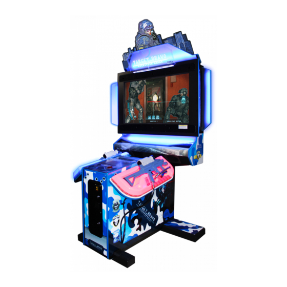
Indicates a warning or caution that, if ignored, may result in the mishandling of the product and cause faulty operation or damage to the product. Sega Amusements Europe Limited. 42 Barwell Business Park, Leatherhead Road, Chessington, Surrey, KT9 2NY. United Kingdom. European Sales: +44 (0) 208 391 8090... - Page 5 SPECIFICATIONS 55inch Cabinet Machine Dimensions: 1.78m (70.1in.) [Width] x 1.13m (44.4in.) [Depth] Machine Height: 2.71m (106.6in.) (Installed) Machine Weight: 250kg Approx (Installed) Power, maximum current: -225w- Rating: 1.2A @ 240vac 2.4A @ 120vac Licensing DYNA Font The typefaces included herein are solely developed by DynaComware.
- Page 6 Definition of 'Site Maintenence Personnel or Other Qualified Individuals’ Procedures not described in this manual or marked as ‘to be carried out by site maintenance personnel or other qualified professionals’ should not be carried out by personnel without the necessary skill or technology. Work carried out by unqualified persons may cause serious accidents, including electrocution. Parts replacement, maintenance inspections and troubleshooting should be carried out by site maintenance personnel or other qualified professionals.
- Page 7 The symbol shown below will be placed on all products manufactured from 13th August 2005, which indicates this product must NOT be disposed of with other normal waste. Upon purchasing any EEE from SEGA Amusements International Ltd. The user accepts responsibility to dispose of their waste equipment by arranging to return it to a designated UK collection point (AATF) or an Approved Exporter (AE) for the correct recycling of waste electrical and electronic equipment.
-
Page 8: Table Of Contents
TABLE OF CONTENTS INTRODUCTION HANDLING PRECAUTIONS PRECAUTIONS REGARDING INSTALLATION PRECAUTIONS REGARDING OPERATION 3-1 BEFORE OPERATION 3-2 PAYING ATTENTION TO CUSTOMERS PART DESCRIPTIONS ACCESSORIES ASSEMBLY AND INSTALLATION 6-1 INSTALLING THE CABINET 6-2 FIXATION TO SITE 6-3 POWER SUPPLY AND OTHER CONNECTIONS 6-4 TURNING ON THE POWER 6-5 CONFIRMATION OF ASSEMBLY 6-6 APPLYING WARNING LABELS (EPILEPTIFORM SEIZURES) - Page 9 EXPLANATION OF TEST AND DATA DISPLAY 9-1 SWITCH UNIT AND COIN METER. 9-2 SYSTEM TEST MODE 9-3 GAME TEST MODE 9-4 SYSTEM INFORMATION 9-5 STORAGE INFORMATION 9-6 JVS TEST 9-7 MONITOR TEST 9-8 SPEAKER TEST 9-9 COIN ASSIGNMENTS 9-10 CLOCK SETTINGS 9-11 NETWORK TEST 9-12 EXIT CONTROLLER UNIT(S)
- Page 10 16-3 RINGWIDE COMPONENTS 16-4 ERROR CODES DISPLAY 16-5 REPLACING THE BUTTON BATTERY 16-6 CLEANING RINGWIDE 16-7 GAME BOARD (RINGWIDE) LOCATION AND REMOVAL FUSES AND FUSE REPLACEMENT 17-1 CONTROLLER AND LED FUSE REPLACEMENT 17-2 MAIN FUSE REPLACEMENT 17-3 AC DISTRIBUTION FUSE BD DESIGN-RELATED PARTS PARTS LIST WIRE COLOUR CODE TABLE...
-
Page 11: Handling Precautions
• SEGA shall not be held responsible for damage or compensation for damage to a third party caused by specification changes not designated by SEGA. - Page 12 • Some parts are not designed or manufactured specifically for this game machine. The manufacturers may discontinue or change the specifications of such general-purpose parts. If this is the case, SEGA cannot repair or replace a failed game machine whether or not a warranty period has...
- Page 13 CONCERNING THE STICKER DISPLAY This SEGA product has stickers attached describing the product manufacture No. (Serial No.) and Electrical Specifications. It also has a Sticker describing where to contact for repair and for purchasing parts. When inquiring about or asking for repairs, mention the Serial No. and Name of Machine indicated on the Sticker.
-
Page 14: Precautions Regarding Installation
PRECAUTIONS REGARDING INSTALLATION • This product is an indoor game machine. Do not install it outside. Even indoors, avoid installing in places mentioned below so as not to cause fire, electric shock, injury and/or malfunction: • Places subject to rain/water leakage or places subject to high humidity, in the proximity of an indoor swimming pool and/or shower, etc •... - Page 15 Securing a safe area for operation as described in this manual will ensure safe operation for players and observers. SEGA shall not be held responsible for damage or compensation for damage to a third party, resulting from the failure to observe this instruction.
- Page 16 • To install this product, the entrance must be at least 1.45m (57.1in) in width and 2.1m (82.6in) in height (without Assy Billboard) and 2.45m (96.4in) (with Assy Billboard). If the entrance is too narrow, do not tilt the product carelessly. If all the product weight is put on the casters at one side only, there could be damage or deformation, causing serious accidents such as workers getting caught underneath.
- Page 17 To install this product, the entrance must be at least 1.8m (70.8in) in width and 2.37m (93.3in) in height (without Assy Billboard) and 2.75m (108.2in) in height (with Assy Billboard). If the entrance is too narrow, do not tilt the product carelessly.
-
Page 18: Precautions Regarding Operation
PRECAUTIONS REGARDING OPERATION To avoid injury and trouble, be sure to pay attention to the behaviour of visitors and players. 3-1 BEFORE OPERATION • In order to avoid accidents, check the following before starting the operation: • To ensure maximum safety for the players and the customers, ensure that where the product is operated has sufficient lighting to allow any warnings to be read. - Page 19 • To avoid injury, be sure to provide sufficient space by considering the potentially crowded situation at the installation location. Insufficient installation space can cause contact, collisions, and/or trouble between customers. • During daily cleaning, be sure to check the surface of the control unit and other parts that the player touches with his/her hands for damage, cracks, or loose screws.
-
Page 20: Paying Attention To Customers
3-2 PAYING ATTENTION TO CUSTOMERS To avoid injury and trouble, be sure to constantly give careful attention to the behaviour and manner of the visitors and players. DURING OPERATION (PAYING ATTENTION TO CUSTOMERS) • For safety reasons, do not allow any of the following people to play the game: Those who have high blood pressure or a heart problem. - Page 21 ● Players directly hold the control unit with their bare hands, so it is recommended that wet towels (paper towels) be provided. ● Diligently clean the parts that players touch directly to ensure a pleasant game playing experience. ● Inspect the coin insertion slots to make sure no foreign objects have been in- serted and that they have not otherwise been tampered with as this will prevent play.
-
Page 22: Part Descriptions
PART DESCRIPTIONS Assy Upper Reflector Assy Billboard Assy LCD Assy Reflector R Assy Reflector L Assy Control Panel Assy Gun Holder R Assy Gun Holder L Assy DFMD Assy Controllers Assy Game Bd... -
Page 23: Accessories
ACCESSORIES Confirm that the accessories listed in the table below are present when setting up the product. Accessories marked “Spare” in the note column are consumable items but included as spares. Part name / number Diagram Quantity Owner’s Manual (Pt No 420-7353-01UK) Master key Security Key Power Lead... -
Page 24: Assembly And Installation
ASSEMBLY AND INSTALLATION • Perform assembly work by following the procedure herein stated. Failure to comply with the instructions can cause electric shock. • Perform assembly as per this manual. Since this is a complex machine, incorrect assembling can cause an electric shock, machine damage and/or improper functioning as per specified performance. -
Page 25: Installing The Cabinet
INSTALLING THE CABINET • To perform work safely and securely, be sure to prepare a step which is in a safe and stable condition. Performing work without using a step may lead to injury or damage to components. Tools required for installation Wrench (M6) Wrench (M8) Adjustable wench... - Page 26 6-1-1 INSTALLING THE ASSY REFLECTOR L & R • The Side Reflectors weigh approx 3kg and the Upper Reflector approx 5kg. Have at least 2 people performing this operation. Working alone could result in personal injuries, etc. • To perform work safely and securely, be sure to prepare a step which is in a safe and stable condition.
- Page 27 6-1-2 INSTALLING THE BILLBOARD HEADER • To perform work safely and securely, be sure to prepare a step which is in a safe and stable condition. Performing work without using a step may lead to injury or damage to components. Fit and secure the Billboard to the top of the Display Cabinet in the position shown using M5x12 M SCR PAN PAS (2).
- Page 28 6-1-3 INSTALLING THE ASSY UPPER REFLECTOR • The Upper Reflector weighs approx 5kg. Have at least 2 people performing this operation. Working alone could result in personal injuries, etc. • To perform work safely and securely, be sure to prepare a step which is in a safe and stable condition.
-
Page 29: Fixation To Site
FIXATION TO SITE • Make sure that all the adjusters contact the floor. Otherwise the cabinet could move, causing an accident. • Provide a ventilation space at least 20cm wide behind the cabinet. There are ventilation holes on the back of the cabinet. Do not block the ventilation holes. Doing so could trap heat inside resulting in fire. - Page 30 • Provide a ventilation space at least 20cm wide behind the cabinet. There are ventilation holes on the back of the cabinet. Do not block the ventilation holes. Doing so could trap heat inside resulting in fire. It could also result in equipment damage or cause parts to become exhausted prematurely.
-
Page 31: Power Supply And Other Connections
POWER SUPPLY AND OTHER CONNECTIONS • Use the power supply equipped with an earth leakage breaker. Use of power supply without such a breaker could result in fire if there is a current leakage. • Have available a securely grounded indoor ground terminal. Without proper grounding, customers could be electrocuted and product operations might not always be stable. -
Page 32: Turning On The Power
Set the main switch of the AC unit to ON and engage the power. When you turn on the power, a loading screen will be displayed on screen. After the SEGA LOGO start up screen is displayed on the LCD screen, the Advertise (Attract) Mode will start. - Page 33 COMPONENTS WHICH CHANGE STATE WHEN POWER IS APPLIED Soldier/Skyline illuminates Billboard illuminates LCD screen powers on, shows SEGA logo then attract LEDs reflect of panels in attract Sound is emitted from speakers Coin door lamp illuminates LEDs illuminate from front and rear of gun housing.
-
Page 34: Confirmation Of Assembly
CONFIRMATION OF ASSEMBLY In the test mode, ascertain that the assembly has been made correctly and IC Board is satisfactory. In the test mode, perform the following tests (refer to chapter 9): 9-3-3 INPUT TEST This menu is used to test the system inputs such as triggers, pedals and buttons. To implement the test, press each device that is listed and check the results on screen. -
Page 35: Applying Warning Labels (Epileptiform Seizures)
6-6 APPLYING WARNING LABELS (EPILEPTIFORM SEIZURES) • The operator MUST apply the Epileptiform Seizure Label to this product. Failing to apply this label may result in the player/observer suffering from a photosensitive seizure. Warning the potential player/observer of this before the start of a game may prevent such accidents. •... -
Page 36: Precautions When Moving The Machine
PRECAUTIONS WHEN MOVING THE MACHINE • Always disconnect the power cable before moving the product. If it is moved with the power cable connected, the cable could be damaged, causing fire or electric shock. • To move the unit over the floor, pull in the adjusters and have the casters contact the floor. -
Page 37: Precautions When Moving From Site
PRECAUTIONS WHEN MOVING FROM SITE • When moving the cabinet, do not grip or push the Reflector Plates. Doing so could deform or damage the part. • If moving through a door or place with a low ceiling such as an elevator, you should take apart the billboard and Upper Reflector plate. -
Page 38: Game Description
GAME DESCRIPTION HOW TO PLAY When you insert coins, they will be counted in the credit display at the bottom of the screen. When you insert enough coins for a game, the message at the bottom will change from “INSERT COIN(S)” to “PRESS START BUTTON,” and the start buttons on both sides will flash. -
Page 39: Reloading
RELOADING When the player has fired all bullets in their ammo clip, the gun will be empty. The player can then reload the weapon by aiming it outside the screen. The player can reload this way even if there are still bullets left. The gun is also reloaded automatically when the trigger is pulled with no ammo remaining. -
Page 40: Rto (Real Time Tactical Order)
8-5 RTO (REAL TIME TACTICAL ORDER) While progressing through the game, the RTO icon will sometimes be displayed at the top of the screen. By pressing the action button while the RTO icon is displayed, the player can issue tactical orders to their teammates. NOTE: Giving tactical orders via the RTO icon makes it easier to progress through the game, but in some cases the player will earn a higher score for progressing without giving tactical orders. -
Page 41: Events
EVENTS Various events occur throughout the course of the game. An explanation of the control method for the event will be displayed before the event begins. Successfully completing events will lead to an increase in the mission success rate (the evaluation displayed after clearing the mission), and the player can earn a higher score. -
Page 42: Game Over
Shooting the boss drains the boss’ LIFE gauge. Attacking the boss’ weak point drains the boss’s LIFE gauge significantly. When the boss’ LIFE gauge reaches zero, the boss is defeated. BOSS’S WEAK POINT PROMPT BOSS BATTLE screen 2 GAME OVER If both players run out of LIFE, the game ends. -
Page 43: Continue Play Bonus
8-10 CONTINUE PLAY BONUS The player receives body armour as a continue play bonus when they choose to continue. Body armour will take the damage from 1 enemy attack while equipped. NOTE: This feature can be set in GAME TEST MODE (see 11-5). CONTINUE PLAY BONUS screen CONTINUE PLAY BONUS PROMPT... -
Page 44: Explanation Of Test And Data Display
EXPLANATION OF TEST AND DATA DISPLAY Perform tests and data checks periodically by manipulating the TEST Button and SERVICE Button in the cabinet. Follow the instructions in this chapter to conduct checks when the game machine is first installed, when money is being collected, or when the game machine does not operate properly. -
Page 45: Switch Unit And Coin Meter
9-1 SWITCH UNIT AND COIN METER. Never touch places other than those specified. Touching places not specified can cause electric shock and short circuit accidents. • Adjust the sound to the optimum volume, taking into consideration the environmental requirements of the installation location. •... -
Page 46: System Test Mode
9-2 SYSTEM TEST MODE The details of changes to Test Mode settings are saved when you exit from each Test Mode by selecting EXIT. If the power is turned off before that point, changes to the settings will be lost. SYSTEM TEST MODE can be used to check the information or the operation of RINGWIDE, adjust Monitor color, and perform coin/credit settings. -
Page 47: Game Test Mode
9-3 GAME TEST MODE ● To change settings in the GAME TEST MODE, simply making changes on the setting screen will not be effective. Complete the TEST MODE in normal fashion. ● Use with the specified settings. If settings other than those specified are used, inappropriate operations or malfunction may occur. - Page 48 9-3-2 BOOKKEEPING Each game record can be viewed: BOOKKEEPING 1/3 COIN CHUTE #1 COIN CHUTE #2 TOTAL COINS COIN CREDITS SERVICE CREDITS TOTAL CREDITS PRESS TEST BUTTON TO CONTINUE BOOKKEEPING SCREEN 1/3 COIN CHUTE #1 Number of coins inserted in coin chute 1. COIN CHUTE #2 Number of coins inserted in coin chute 2.
- Page 49 Bookkeeping – Page 2 – Data on Average Game Times BOOKKEEPING 2/3 NUMBER OF GAMES NUMBER OF GAME START NUMBER OF GAME JOIN NUMBER OF CONTINUE TOTAL TIME *D **H **M **S PLAY TIME *D **H **M **S AVERAGE PLAY TIME **M **S LONGEST PLAY TIME **M **S...
- Page 50 Bookkeeping – Page 3 – Data on Game Mode Plays BOOKKEEPING 3/3 0M : 00S - 0M : 29S 0M : 30S - 0M : 59S 1M : 00S - 1M : 29S 1M : 30S - 1M : 59S 2M : 00S - 2M : 29S 2M : 30S - 2M : 59S 9M : 00S - 9M : 29S...
- Page 51 9-3-3 INPUT TEST Select INPUT TEST to display the following screen and check the status of input devices. This test should be used periodically to check that each input device is functioning correctly. INPUT TEST PLAYER TRIGGER ACTION CHANGE SIGHT-X SIGHT-Y SCREEN START...
- Page 52 9-3-4 OUTPUT TEST This screen is for confirming the proper operation of each output device used by the game. Periodically use this screen to check the status of each output device. OUTPUT TEST 1P START LAMP 1P RECOIL 1P HOLDER LAMP 2P START LAMP 2P RECOIL 2P HOLDER LAMP...
- Page 53 9-3-5 GAME ASSIGNMENTS Adjust all game settings. GAME ASSIGNMENTS DIFFICULTY NORMAL LIFE REACTION ADVERTISE SOUND DAMAGE EFFECT ARMOUR DRESS CODE SWIPE CARD TO PLAY EXIT SELECT WITH SERVICE AND PRESS TEST BUTTON GAME ASSIGNMENTS screen ■ Controls - Press the SERVICE Button to select menu item. - Press the TEST Button to change the value of the selected item.
- Page 54 Sets whether female soldier designs will be included in boss images to ON/OFF (default setting: OFF). DRESS CODE Female soldier designs will not be included in boss images. Female soldier designs will be included in boss images. Sets the changing of the INSERT COIN(S) display to SWIPE CARD TO PLAY to ON/OFF (default setting: OFF).
- Page 55 9-3-6 LED ADJUSTMENT Conduct adjustment of the full-colour LEDs surrounding the monitor. LED ADJUSTMENT MAX R MAX G MAX B SET DEFAULT COLOUR PATTERN EXIT BOARD STATE READY SELECT WITH SERVICE AND PRESS TEST BUTTON LED ADJUSTMENT screen ■ Controls - Press the SERVICE Button to select menu item.
- Page 56 9-3-7 CONTROLLER ADJUSTMENT This screen allows for the adjustment of the control unit’s crosshair settings which are used during gameplay. CONTROLLER ADJUSTMENT LEFT LEFT CENTER X CENTER X CENTER Y CENTER Y BOTTOM BOTTOM RIGHT RIGHT CHECK CHECK CANCEL CANCEL DEFAULT DEFAULT EXIT (WITH SAVE)
- Page 57 9-3-8 BACKUP DATA CLEAR Delete various game data. BACKUP DATA CLEAR YES (CLEAR) NO (CANCEL) SELECT WITH SERVICE BUTTON AND PRESS TEST BUTTON BACKUP DATA CLEAR screen (1/2) BACKUP DATA CLEAR COMPLETED PRESS TEST BUTTON TO EXIT BACKUP DATA CLEAR screen (2/2) ■...
-
Page 58: System Information
9-4 SYSTEM INFORMATION The SYSTEM INFORMATION screen displays system information. The following information is displayed on this screen. SYSTEM INFORMATION 1/2 The SYSTEM INFORMATION 1/2 screen displays system information. ■ SYSTEM INFORMATION 1/2 Screen SYSTEM INFORMATION 1/2 KEYCHIP KEYCHIP ID A72*-*********** MODEL TYPE REGION MOTHER BOARD MAIN ID ****-***********... - Page 59 SYSTEM INFORMATION 2/2 The SYSTEM INFORMATION 2/2 screen displays system information. Press the TEST Button on the SYSTEM INFORMATION 2/2 screen to return to the SYSTEM TEST MODE screen. ■ SYSTEM INFORMATION 2/2 Screen SYSTEM INFORMATION 2/2 VOLTAGE CPU CORE +*.**[V] VOLTAGE 3.3V +*.**[V] VOLTAGE 5V +**.**[V] VOLTAGE 12V...
-
Page 60: Storage Information
9-5 STORAGE INFORMATION The STORAGE INFORMATION screen displays information on the game stored in the program installer device. This screen is also used when uninstalling the game stored within the program installer device. Until preparations to launch the game are complete, a now checking screen will be displayed and uninstall cannot be performed. -
Page 61: Jvs Test
If no JVS I/O boards are connected, the message “NO JVS NODE” will be displayed. ■ JVS TEST Screen JVS TEST INPUT TEST NODE -> EXIT NAME SEGA ENTERPRISES,LTD.: I/O BD JVS :837-13551: Ver1.00 CMD VER JVS VER COM VER SWITCH... - Page 62 The following information is displayed on this screen. The currently displayed JVS I/O board number and the total number of connected NODE JVS I/O boards NAME Name of the connected I/O board, etc. CMD VER Command format version JVS VER JVS standard version COM VER Communication version...
- Page 63 JVS INPUT TEST Use the JVS INPUT TEST to test the JVS input. The hexadecimal input information from the JVS I/O board will be displayed in real time. ■ JVS INPUT TEST Screen JVS TEST INPUT TEST NODE SYSTEM ROTARY 0000 PLAYER 0000 ROTARY 0000 PLAYER 0000...
-
Page 64: Monitor Test
9-7 MONITOR TEST Use MONITOR TEST to check the output of the monitor. Enter MONITOR TEST and the MONITOR TEST 1/2 Screen will be displayed. ■ MONITOR TEST Screen 1/2 MONITOR TEST 1/2 PRESS TEST BUTTON TO NEXT Press TEST Button and the screen will change to the MONITOR TEST 2/2 Screen. ■ MONITOR TEST Screen 2/2 MONITOR TEST 2/2 PRESS TEST BUTTON TO EXIT... -
Page 65: Speaker Test
9-8 SPEAKER TEST Use SPEAKER TEST to check the output of each speaker by having them each emit a test sound. Select each speaker with the cursor and press the TEST Button to turn that speaker ON or OFF. When set to ON a test sound will be emitted from that speaker. It is possible to set multiple speakers to emit the test sound at the same time. -
Page 66: Coin Assignments
9-9 COIN ASSIGNMENTS Use COIN ASSIGNMENTS to alter the credit settings. The game will award players the number of credits determined here. Settings will only be saved if they have been changed. ■ COIN ASSIGNMENTS Screen COIN ASSIGNMENTS COIN CHUTE TYPE COMMON •••••••••••••••••••••• (A) SERVICE TYPE COMMON •••••••••••••••••••••••••... - Page 67 (C-1) COIN CHUTE #1 COIN TO CREDIT RATE (Coin and credit conversion rate 1) 1 COIN(S) COUNT AS 1 CREDIT(S) 1 coin counts as 1 credit 2 COIN(S) COUNT AS 1 CREDIT(S) 2 coins count as 1 credit 3 COIN(S) COUNT AS 1 CREDIT(S) 3 coins count as 1 credit 4 COIN(S) COUNT AS 1 CREDIT(S) 4 coins count as 1 credit...
- Page 68 The following information is displayed on this screen. (E-1) COIN CHUTE #1 MULTIPLIER Coin conversion rate for #1 (how many coins 1 inserted coin counts for). (E-2) COIN CHUTE #2 MULTIPLIER Coin conversion rate for #2 (how many coins 1 inserted coin counts for). NOTE: When (A) COIN CHUTE TYPE is set to “COMMON,”...
- Page 69 (H) GAME COST SETTING Use the COIN ASSIGNMENTS GAME COST SETTING screen to set the cost (number of required credits) that the game program will use to determine if there are enough credits to play the game. A total of 8 game costs can be defined. The game cost is defined by the BOOT ID, and when the second boot recognizes the game, the game cost defined by the BOOT ID will be displayed.
-
Page 70: Clock Settings
9-10 CLOCK SETTINGS Use CLOCK SETTING to set the date and time. Use the SERVICE Button to move the cursor to the category that you wish to change and press the TEST Button to increase that value. Holding the TEST Button down will make the value continuously increase. ■... - Page 71 CLOCK SETTING CLOCK 20**/ */ *(TUE) 12:00:00 TIMEZONE UTC+09:00 DAYLIGHT SAVING TIME(DST) •••••••••••••••••••••• ENABLE DST START MAR/2nd/SUN 02:00:00 DST END NOV/1st/SUN 02:00:00 -> EXIT SELECT WITH SERVICE BUTTON AND PRESS TEST BUTTON [DAYLIGHT SAVING TIME (DST): ENABLE] (C) DAYLIGHT SAVING TIME (DST) Displays the daylight saving time setting.
-
Page 72: Network Test
9-11 NETWORK TEST Use NETWORK SETTING to determine network settings or to test the network. There is no need to alter these settings for a game that does not use a network. ■ NETWORK SETTING (Setting Menu) Screen NETWORK SETTING MAIN NETWORK NETWORK TEST -> EXIT SELECT WITH SERVICE BUTTON AND PRESS TEST BUTTON The following information is displayed on this screen. - Page 73 MAIN NETWORK Select MAIN NETWORK on the NETWORK SETTING (Setting Menu) and the following screen will be displayed. ■ NETWORK SETTING (Network Setting) Screen NETWORK SETTING MAC ADDRESS **-**-**-**-**-** ••••••••••••••••••• A DHCP ******** •••••••••••••••••••••••• B IP ADDRESS ••••••••••••••••••••••••••••••••••• C ***.***.***.*** SUBNET MASK ••••••••••••••••••••••••••••••••• D ***.***.***.*** GATEWAY ••••••••••••••••••••••••••••••••••••...
-
Page 74: Exit
NETWORK TEST Check the network connection. The test will begin as soon as this screen is displayed. The machine cannot be operated until the test is finished. ■ NETWORK TEST Screen NETWORK TEST DHCP ------------ **** LOOPBACK -------- **** LINKUP ---------- **** GATEWAY --------- **** ROUTER ---------- **** HOPS SERVER ---------- ****... -
Page 75: Controller Unit(S)
10 CONTROLLER UNIT(S) ● Before starting work, be sure to turn the power off. Working without turning the power off can cause an electric shock or short circuit. ● Be careful not to damage the cables. Damaged cables may cause electric shock, short circuit or present a risk of fire. - Page 76 If the control unit does not operate satisfactorily and adjustments in TEST MODE are ineffective, it could be that parts inside the control unit have been damaged. Follow the steps given below to remove the control unit, dismantle unit and replace parts. To replace parts in the control unit, remove the speaker unit and detach the L and R covers of the outer part.
-
Page 77: Removing The Controller Uits
10-1 REMOVING THE CONTROLLER UNITS Remove the 1P/2P control unit. Turn power off. Unlock and remove side service door. 1&2 Player Controllers Remove top panel... - Page 78 Locate the connectors for each of the controllers and disconnect. Locate and disconnect Player 1 controller connector Remove the M4x16 M SCR TMP PRF CRM (4) from the cable housing at the side of the cabinet. Once removed carefully pull the connector through the access hole. M4x16 M SCR CRM TMP PRF (4) The controller can now be removed from the cabinet...
-
Page 79: Removing The Controller Support
10-2 REMOVING THE CONTROLLER SUPPORT Refer to 10-1“REMOVING THE CONTROL UNIT “ and take off the control unit. Using an Allen wrench, remove the 6 hexagon socket head screws, and take off the 4 controller supports. NOTE: When reattaching reinforcement parts, always refer to the fiture to ensure that screws are not put into the wrong places. -
Page 80: Removing The Scope
10-3 REMOVING THE SCOPE Refer to 10-1 “REMOVING THE CONTROL UNIT ”and take off the control unit. Remove the 2 screws and take off the lens cap. LENS CAP SCREW (2) M3 x 12, w/flat & spring washers Remove the 7 screws and take off the scope body L. SCREW (7) M3 x 12, w/flat &... - Page 81 Remove the 1 screw and undo the 1 cord clamp. TAPPING SCREW (1) M4 x 8 CORD CLAMP (1) Disconnect the 1 connector. CONNECTOR (1) PA2P Remove the scope body R from the control unit. At this point, the speaker net and speaker come loose easily, so be careful not to lose them.
-
Page 82: Removing The Microswitch
10-4 REMOVING THE MICROSWITCH There are microswitches for the trigger and shot selector and action button inside the control unit. Refer to 14-2 “REMOVING THE CONTROLLER SUPPORT ” and 14-3 “REMOVING THE SCOPE,” take off the controller support and scope body. Place cover R face down on the work surface and remove the 15 screws to take off the cover L. - Page 83 Remove the soldered part and then remove the microswitch. MICROSWITCH 509-5080 Solder and attach the new microswitch. Protect the soldered part with heat-shrinkable tubing. Refer to Step 1 to 4 and work in reverse order to reassemble the control unit. Be careful not to tighten screws excessively.
-
Page 84: Replacing The Solenoid
10-5 REPLACING THE SOLENOID Refer to 14-2 REMOVING THE CONTROLLER SUPPORT” and 14-3 “ REMOVING THE SCOPE” to “ take off the controller support and scope body. Refer to Step 2 of 14-4 “REPLACING THE MICROSWICH” and take off the cover L. Disconnect the 1 connector. - Page 85 Remove the 8 screws and replace the solenoid. OTE: When attaching it, use a thread sealant. SCREW (8) M3 x 6, w/spring washer SOLENOID 124-5113 Refer to Step 1 to 5 and work in reverse order to reassemble the control unit. Refer to the figure and be careful with the order in which the small parts are attached and the direction the side with the solenoid cable faces.
-
Page 86: Graphics Display
GRAPHICS DISPLAY 11-1 PRECAUTIONS WHEN HANDLING THE LCD DISPLAY [Responding to breakdown or abnormality] ● If you notice smoke or an odd smell, immediately unplug the power cable from the power plug. Continuing to use the product may cause a fire or an electric shock. -
Page 87: Cleaning The Screen Surface
● Do not tap or strike the surface of the LCD, as doing so may break the glass and cause injury. If the glass breaks and the liquid crystal leaks out, do not touch the liquid. The liquid can cause damage if it comes into contact with eyes or skin. -
Page 88: Screen Adjustment
11-3 ADJUSTMENT METHOD All adjustment values are set accurately at the time of shipping from the factory. Do not re-adjust these values needlessly or apply adjustments not specified in this manual. The display may not appear properly if the values are incorrect. - Page 89 55” LCD Panel On-screen display controls Power Supply LCD Controller PCB 11-3 ADJUSTMENT METHOD Button Names and Functions 11-3 Fig. 03 MENU: Turn the Picture Menu display ON and OFF. SELECT: Gains entry to the Item selected in the menu (highlights in yellow when selected). Exits the Item adustment.
- Page 90 On-Screen Display (OSD) Press the MENU Button while the OSD is not displayed to bring up the Picture Menu. On the Picture Menu, it is possible to perform various screen adjustments. 11-3 Fig. 04 Use the UP and DOWN Buttons to move the ‘Black Bar’to the item you want to adjust. After selecting the desired item, pressing the SELECT Button will extend the MENU Screen and allow adjustments to be changed.
- Page 91 On-Screen Display (OSD) <continued> 11-3 Fig. 06 Available Settings (Selects Operation Mode)) Selection availble - 6500K - 9300K - USER BRIGHTNESS (Adjust Brightness) Adjust screen Brightness. - Values: 0 - 100 (0” being the darkest setting, and “100” being the brightest) CONTRAST (Adjust Contrast) Adjust Contrast level.
-
Page 92: Coin Handling
COIN HANDLING Handling the Coin Jam If the coin is not rejected when the REJECT button is pressed, open the coin chute door and open the selector gate. After removing the jammed coin, put a normal coin in and check to see that the selector correctly functions. - Page 93 CLEANING THE COIN SELECTOR (MECHANICAL). Remove and clean smears by using a soft cloth dipped in water or diluted chemical detergent and then squeezed dry. Remove the CRADLE.. When removing the retaining ring (E ring) be very careful so as not to bend the rotary shaft. Remove stain from the rotary shaft and CRADLE shaft receiving portions by wiping off with a...
- Page 94 CLEANING THE COIN SELECTOR (SR3 / NRI) Remove and clean smears by using a damp soft cloth dipped in water. DO NOT use any diluted chemical detergent or cleansing agent as this will impair the workings of the component. GATE Open the reject gate to gain access to the rundown path.
-
Page 95: Fault Finding
12-2 FAULT FINDING Fault Finding The following information is presented for customers’ guidance in rectifying a fault but does not cover all possible causes. All acceptors with electronic faults should be returned to an approved service centre for repair. SYMPTOM INVESTIGATE POSSIBLE CAUSE Poor Contact... -
Page 96: Adjusting The Price Of Play (Excel)
12-3 ADJUSTING THE PRICE OF PLAY (EXCEL) ● The price of play is determined by the configuration of switches located on either an EXCEL board or VTS board. The type of board used is determined by product location. Switch settings for both types of board remain the same. This product comes equipped with a Crane NRI Coin Acceptor. -
Page 97: Adjusting The Price Of Play (Vts)
12-4 ADJUSTING THE PRICE OF PLAY (VTS) This product comes equipped with a Crane NRI Coin Acceptor. To adjust the price of play ALL credit setting are adjusted via the VTS CREDIT BOARD. IMPORTANT! The CREDIT SETTINGS within the SYSTEM TEST MODE must be set to 1 coin 1 credit to allow the CREDIT BOARD to function correctly. -
Page 98: Lamps And Lighting
LAMPS AND LIGHTING • When working with the product, be sure to turn the power off. Working with the power on may cause an electric shock or short circuit. • You may get burned by a hot fluorescent lamp or other lamps. Pay full attention to the lamps when performing the work. -
Page 99: Start Button Lamp Replacement
13-2 START BUTTON LAMP REPLACEMENT MAKE SURE THAT THE MAIN SUPPLY VOLTAGE TO THE MACHINE IS SWITCHED OFF BEFORE ATTEMPTING TO CARRY OUT THIS WORK Before replacing any lamp, TURN THE POWER OFF. To gain access to the Start Lamps, first remove the Control Panel by unscrewing the 4 M4x16 Socket Cap Screws (4) fitted at each corner. -
Page 100: Screen Led Strip Replacement
13-3 SCREEN LED STRIP REPLACEMENT Before replacing any lamp, TURN THE POWER OFF. To gain access to the Screen LED Strips, access the back of the Monitor by unlocking the back service door. Back Service Door Disconnect the connector between the LED Strip and the Cabinet. LED Strip Connector... - Page 101 Remove the corresponding Reflector to access LED Strip (for Reflector removal, please refer to Chapter 6-1-1). Remove LED Strip from cable housing and replace with new Strip. LED Strip Cable Housing Reapply Reflectors securely.
-
Page 102: Periodic Inspection
PERIODIC INSPECTION The items listed below require periodic check and maintenance to retain the performance of this machine and to ensure safe business operation. When handling the controller, the player will be in direct contact with it. In order to always allow the player to enjoy the game, be sure to clean it regularly. - Page 103 Cleaning the Cabinet Surfaces When the cabinet surfaces are badly soiled, remove stains with a soft cloth dipped in water or diluted (with water) chemical detergent and squeezed dry. To avoid damaging surface finish, do not use solvents such as thinner, benzine, etc. other than ethyl alcohol, or abrasives, bleaching agent and chemical dustcloth. Some general-purpose household, kitchen and furniture cleaning products may contain strong solvents that degrade plastic components, coatings, and print.
-
Page 104: Troubleshooting
TROUBLESHOOTING 15-1 TROUBLESHOOTING (WHEN NO ERROR MESSAGE IS SHOWN) • This work should be performed by site maintenance personnel or other skilled professionals. Work performed by non-technical personnel can cause a severe accident such as an electric shock. If there are no site maintenance personnel or other skilled professionals available, turn off the power immediately and contact the office given in this manual or from point of purchase. - Page 105 If a problem occurs, first check to make sure that the wiring connectors are properly connected. 15 TABLE 01 PROBLEM CAUSE COUNTERMEASURES The power is not ON. Firmly insert the plug into the outlet. Make sure that the power supply/voltage Incorrect power source/voltage.
-
Page 106: Game Board
GAME BOARD ● When working with the product, be sure to turn the power off. Working with the power on may cause an electric shock or short circuit. ● Be careful not to damage the wires. Damaged wires may cause an electric shock, short circuit or present a risk of fire. -
Page 107: Handling Precautions
RINGWIDE. Failure to observe these instructions may cause overheating and fire. ● Always follow the usage conditions from SEGA as well as the usage conditions for the cabinet you are using for RINGWIDE. Failure to do so may cause an overheating and fire. -
Page 108: Parts Details
16-2 PARTS DETAILS Shield case Exhaust vent (Do not block or cover.) Intake vent (Do not block or cover.) Board number Board serial number... - Page 109 ● Do not connect components to JVS I/O that are not designated by SEGA. Connecting unspecified components could cause an accident such as an electric shock or fire.
- Page 110 1 Power Input Port Terminal Signal Terminal Signal Name Name +12V DC IN +12V DC IN +12V DC IN +12V DC IN NOTE: Before connecting, be sure to check the type of connector. 2 External Power Supply Port Terminal Signal Terminal Signal Maximum Output Current...
- Page 111 4 DIP SW No. 1, No. 2 and No.3: Use differs depending on game software. Set according to the Service Manual provided with the game software itself. No. 4: Changes the facing of the monitor. Use differs depending on game software. Set according to the Service Manual provided with the game software itself.
-
Page 112: Ringwide Components
16-3 RINGWIDE COMPONENTS ■ ACCESSORIES Parts not labeled with part numbers are as yet unregistered or cannot be registered. Be sure to handle all parts with care, as some parts are not available for purchase separately. DESCRIPTION/PART NO. FIGURES/NOTES TAPPING SCREW 011-P00412 Used for installing the RINGWIDE. -
Page 113: Error Codes Display
16-4 ERROR CODES DISPLAY ● If an error code is displayed, get on-site maintenance personnel or other qualified professional to look at it. An unqualified person attempting to resolve an error code problem may lead to electric shock, short circuit and risk of fire. If no on-site maintenance personnel or qualified professional is available, immediately turn off the power and contact the customer services in this manual or your supplier. - Page 114 DISPLAY Error 0008 Keychip Access Failed CAUSE The key chip could not be accessed. COUNTERMEASURES Reinsert the key chip and restart RINGWIDE. If this does not fix the problem, contact the office listed in this manual or the point of purchase for this product. DISPLAY Error 0010 Unexpected Game Program Failure...
- Page 115 DISPLAY Error 0042 Game Program Not Found on Install Media CAUSE Some part of the game program is missing. COUNTERMEASURES Check how the game was installed. If this does not fix the problem, contact the office listed in this manual or the point of purchase for this product.
- Page 116 DISPLAY Error 0082 Game Program Access Failed CAUSE The storage device cannot be recognized. COUNTERMEASURES Reinstall the game program. If this does not fix the problem, contact the office listed in this manual or the point of purchase for this product. DISPLAY Error 0083 Storage Device Not Acceptable...
- Page 117 DISPLAY Error 0531 (No message) CAUSE The connected graphics device cannot be recognized. COUNTERMEASURES Turn the power off and then restart the RINGWIDE. If this does not fix the problem, contact the office listed in this manual or the point of purchase for this product. DISPLAY Error 0532 (No message)
- Page 118 DISPLAY Error 0906 Sound Function Not found CAUSE The RINGWIDE sound function cannot be recognized. COUNTERMEASURES Contact the office listed in this manual or the point of purchase for this product. DISPLAY Error 0907 Not Enough System Memory CAUSE RINGWIDE does not have enough memory. COUNTERMEASURES Contact the office listed in this manual or the point of purchase for this product.
- Page 119 DISPLAY Error 8001 Network address error (DHCP) CAUSE The network connection settings could not be initialized. COUNTERMEASURES Check the network connection and follow the startup procedures to restart the system. DISPLAY Error 8002 Network setting error (SYSTEM) CAUSE The SYSTEM TEST MODE NETWORK SETTING is incorrect. COUNTERMEASURES Check the NETWORK SETTING.
- Page 120 DISPLAY Error 8103 ALL.Net System error (TIMEOUT) CAUSE A connection could not be established with ALL.Net. COUNTERMEASURES Check the RINGWIDE network connection, the in-store network connection and the connection between the ALL.Net router and the network cable, and then follow the startup procedures to restart the system. If the error persists, check the maintenance information.
- Page 121 DISPLAY Error 8202 ALL.Net System error (REG) CAUSE ALL.Net registration could not be confirmed. COUNTERMEASURES Check to make sure ALL.Net registration (the agreement) has been successfully completed. DISPLAY Error 8301 Network error (GAME-LAN) CAUSE The connection with the devices that make up this game could not be confirmed.
- Page 122 Other ERROR codes. DISPLAY Error 1000 Force Feedback Error CAUSE Failed to initialise motor controller during power on cycle. COUNTERMEASURES Check all connection to and from Motor Controller. Possible failure of Motor Controller PCB. Replace and restart. DISPLAY <TICKET ERROR> PLEASE CONTACT OPERATOR CAUSE Ticket has jammed or tickets are empty.
- Page 123 Manual Recovery Use the following procedure to return the RINGWIDE system software to a previous state. Press the TEST and SERVICE Buttons simultaneously with the RINGWIDE power off. Hold the buttons down and turn on the power. After RINGWIDE starts up and the following message is displayed, release the buttons. The system software will recover automatically.
-
Page 124: Replacing The Button Battery
16-5 REPLACING THE BUTTON BATTERY ● Make sure you do not damage the printed board and wires. Such damage can lead to electric shock, short circuit and fire hazard. ● To prevent overheating, explosion, or fire: - Do not recharge, disassemble, heat, incinerate, or short the battery. - Do not allow the battery to come into direct contact with metallic objects or other batteries. - Page 125 The button battery that requires replacement can be found on the main board, inside the RINGWIDE shield case. Remove the unit on which RINGWIDE is placed from the game cabinet. RINGWIDE must be removed still attached to the base (wooden shelf, etc.). Remove 2 screws for the RINGWIDE lid.
-
Page 126: Cleaning Ringwide
16-6 CLEANING RINGWIDE ● Clean RINGWIDE once a year or whenever either “Error 0090” or “Error 0091” occurs. Dust accumulating in game boards may not function properly. ● Set each cabinet to correct settings after cleaning the product. Be sure to set RINGWIDE to correct settings when returning. - Page 127 Clean around installment parts of RINGWIDE in the cabinet with a vacuum cleaner. Be sure not to damage wirings and boards. Electronic devices on boards may damage by static electricity, and be sure not to vacuum electronic devices by a vacuum cleaner. Set each RINGWIDE you removed by the reverse method.
-
Page 128: Game Board (Ringwide) Location And Removal
16-7 GAME BOARD (RINGWIDE) LOCATION AND REMOVAL ● When returning the game board after making repairs or replacements, make sure that there are no errors in the connection of connectors. Erroneous connections can lead to electrical shock, short circuits or fires. ● When connecting a connector, check the direction carefully. Connectors must be connected in only one direction. - Page 129 Disconnect all the connections to Ringwide. Note: When disconnecting connectors always pull by the connector housing and never the wires Remove the M4x16 M SCR (4) from the Ringwide. Ringwide M 4 x 1 6 M a c h i n e Screws (2) M 4 x 1 6 M a c h i n e Screws (2)
- Page 130 Do not open the Game Board without the express permission of SEGA. If for any reason entry has been gained into the Game Board without the permission of SEGA, then all warranty rights become void.
-
Page 131: Fuses And Fuse Replacement
FUSES AND FUSE REPLACEMENT ● In case fuse replacements other than those stated in this manual are necessary, contact where you purchased the product from for inquiries regarding this matter. ● In order to prevent an electric shock, be sure to turn power off and unplug from the socket outlet before performing work by touching the internal parts of the product. - Page 132 Unlock the side service door to gain access to the fuses. Fuse Bd Location Identify the fuse to replace and replace with the same type and value. Failing to replace with the same type and value will cause component damage and may cause a fire. FUSE 0.2 A 250 V (2P SENSOR UNIT) FUSE 2 A 250 V (1P SOLENOID) 514-5143-200...
-
Page 133: Main Fuse Replacement
17-2 MAIN FUSE REPLACEMENT For continued protection against risk of fire, replace only with the same type of fuse having the same electrical ratings. Open the fuse compartment drawer to view the main power fuse. Inside the drawer there are two compartments (a front compartment and a rear compartment). -
Page 134: Ac Distribution Fuse Bd
17-3 AC DISTRIBUTION FUSE BD Unlock the side service door to gain access to the Auxillary Fuse Bd Side Service Door Locate the Distribution PCB and replace fuse with the correct value and type.. Distribution PCB Ceramic Fuse 6.3A Ceramic Fuse 6.3A... -
Page 135: Design-Related Parts
DESIGN RELATED PARTS For the warning display stickers, refer to Section 1. TB-1023UK TB-1025UK TB-1014UK TB-1059UK TB-1062UK TB-2002UK TB-1024UK TB-5054UK TB-1061UK TB-1052UK TB-1060UK TB-2001UK TB-1055UK TB-1056UK... - Page 136 TB-1542UK TB-1532UK TB-1533UK TB-1543UK TB-1534UK TB-1544UK TB-1545UK TB-1535UK TB-1546UK TB-1536UK TB-1547UK TB-1537UK TB-1548UK TB-1538UK TB-1035UK TB-1034UK...
-
Page 137: Parts List
PARTS LIST ASSY STRUCTURE - TARGET BRAVO: OPERATION G.H.O.S.T. GST-0000UK TOP ASSY Target Bravo: Operation GHOST TB-1000UK TB-1001UKP GST-1002UK ASSY MAIN CABI ASSY SUB CABI MAIN ASSY FRONT CABINET GST-1080UKP GST-1502UK ASSY AC UNIT ASSY CONTROLLER CABINET GST-1090UKP ASSY SW UNIT TB-1100UKP ASSY LED DISPLAY TB-1140UKP... - Page 138 1 ASSY AC UNIT (GST-1080UKP) (D-1/1) 101 102 ITEM NO PART NUMBER DESCRIPTION ***1 RD-1541UK AC BRKT ***2 ST-0403UK PLATE AC CAP ***3 LB1096 STICKER PROTECTIVE EARTH ***4 LB1131 LABEL ON/OFF ***101 EP1302 EUROSOCKET FUSED 10A 250VAC ***102 514-5078-5000 FUSE 5X20 CERAMIC SB 5000mA ***103 SW1109 SWITCH ROCKER 250V AC...
- Page 139 2 ASSY SW UNIT (GST-1090UKP) (D-1/1) ITEM NO PART NUMBER DESCRIPTION ***1 GST-1091UK PLATE SW VOL BD ***2 LB1152 STICKER VTS ***3 LB1155 STICKER COINS IN ***4 LB1168 STICKER VOLUME ***101 838-14548-01UK SW & VOL CTL BD ***102 280-L00706-PM STANDOFF 6.4MM HOLE PM ***103 EP1380-01 CREDIT BOARD EXCEL...
- Page 140 3 ASSY 43" LED DISPLAY (TB-1100UKP) (D-1/1) ITEM NO PART NUMBER DESCRIPTION ***1 GST-1101UK PLATE LCD MOUNT ***2 TRF-1210UK PNL PRISMA BD DMODULE ***3 GST-1211XUK GLASS LCD SCREEN PROTECTOR ***4 TRF-1207UK COVER PRIMSA BD DMODULE ***5 GST-1132UK STRIP 42" LED TOP PAC ***101 200-6043-AUO 43"...
- Page 141 4 ASSY FAN GST 12VDC (GST-1350UK) (D-1/1) ITEM NO PART NUMBER DESCRIPTION ***1 GST-1008UK BRKT FAN ***101 260-0012-01UK FAN DC 12V ROHS EEC0 ***102 FN1012 FAN GUARD METAL 120MM (FG 12) ***201 000-P00312-W M3X12 MSCR PAN W/FS PAS ***301 OS1195 RIVET SNAP SR-4080B...
- Page 142 5 ASSY CONTROL PANEL (GST-2000UKP) (D-1/1) ITEM NO PART NUMBER DESCRIPTION ***1 TB-2001UKS PLATE CONTROL PANEL ***101 509-0001-BL BUTTON 12V 1.2W BLU S'POINT S.PO ***102 509-0001-RE BUTTON 12V 1.2W RE S'POINT S.PO ***301 GST-60023UK WH BUTTON...
- Page 143 6 ASSY CONTROLLER (GST-2100) (D-1/2)
- Page 144 6 ASSY CONTROLLER (GST-2100) (D-2/2) ITEM NO PART NUMBER DESCRIPTION GLG-2130X SENSOR UNIT GST-2101 COVER L GST-2102 COVER R GST-2104 MAIN TRIGGER GST-2105 SUB TRIGGER GST-2106 SELECTOR CTF-2107 SELECTOR HOLDER CTF-2108 SELECTOR JOINT CTF-2009 PAD BASE CTF-2110 BEARING HOLDER CTF-2111 CTF-2112 SOLENIOD FRAME CTF-2113...
- Page 145 7 ASSY MAIN BD (TB-4000UKP) (D-1/1) ITEM NO PART NUMBER DESCRIPTION ***1 GST-4001UK BOARD WOODEN BASE MAIN ***2 847-0001D ASSY CASE WDE W 1GB EXP ***3 253-5644-098BE KEY CHIP RGW GST ***101 837-14572 I/O CONTROL BD 3 FOR JVS ***102 838-0038UK AMP 2.1W KEENE EMC ***103...
- Page 146 8 ASSY ELEC (GST-4100UKP) (D-1/1) ITEM NO PART NUMBER DESCRIPTION ***1 GST-4101UK BOARD WOODEN BASE SUB ***2 CFB-4003-01UK EARTH PLATE ***3 GST-4102UK COVER ELEC BOARD ***101 838-14551-02UK AC DISTRIBUTION BD ***102 400-5483 SW REGU EADP-130CF A DELTA ***103 400-075-024-01 PSU 24VDC 75W MW LPS-75-24 ***104 400-050-012-01 PSU 12VDC 50W MW LPS-50-12...
-
Page 147: Wire Colour Code Table
WIRE COLOUR CODE TABLE The DC power wire color for this product is different from previous SEGA titles. Working from the previous wire colors will create a high risk of fire. The color codes for the wires used in the diagrams in the following chapter are as follows:... - Page 148 - SEGA TOTAL SOLUTIONS - 42 Barwell Business Park Leatherhead Road, Chessington, Surrey, KT9 2NY United Kingdom Tel: +44 (0) 208 391 8060 Fax: +44 (0) 208 391 8096 xclusive uppliers of pares To Heathrow Airport...
Need help?
Do you have a question about the TARGET BRAVO OPERATION GHOST and is the answer not in the manual?
Questions and answers