Table of Contents
Advertisement
Advertisement
Table of Contents

Related Manuals for Sega Sonic Allstarts


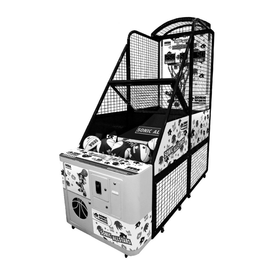
Summary of Contents for Sega Sonic Allstarts
- Page 1 !!!!
-
Page 2: Table Of Contents
Table of Contents I .Product Check-list ....................3 1.Parts list......................4 2. Half-Assembly type parts list ................5 II.Product Specifications .....................6 III. Introduction of Product Appearance ..............6 IV.Assembly and disassembly ..................7 1. Assembly and disassembly for Disassembly type.........7 2. Assembly and disassembly for Half-Assembly type........16 3. -
Page 3: I .Product Check-List
Precautions First, we would like to thank you for choosing our product. We hope you will read the manual before use to maintain user safety and ensure proper operation of the product. In this manual you will find product features, precautions and some simple troubleshooting methods. Please keep this manual in case of future problems or accidents. -
Page 4: Parts List
1.Parts list 1A Sensor for basket 1B Basket kits 2A Basket board 2BR Back right net (WO-RNPW2) stander kit 2BL Back left net 2C 2 Front net 3A Front right net 3B Front left net stander kit stander stander kit stander kit bridge(short) 2E 2 Front net... -
Page 5: Half-Assembly Type Parts List
2. Half-Assembly type parts list Main frame 4B Base holder FB 4C Base holder FF Top cover 5B Ball holder kit Lower Side Net(Frame Included)×4 5C Ball guide kits 6A Ball net holder kit 6B Main part Metal Shelf (optional) Basketball - 5 -... -
Page 6: Ii.product Specifications
II.Product Specifications Position direction Machine Dimensions : W1030×D2500×Top cover H2643mm Weight : 260 kg / 558.4 lbs (Accessories not Included ) (Top cover 6.6kg, Metal Shelf 3.4kg, Lower Side Net 4.2kg×4) Voltage : AC110V~120V/AC220V~240V(50/60Hz) Use Electrical plug display as a glide Located behind the machine. Power Consumption : 200W Fuse : 3A Token size : Ø22mm~27mm... -
Page 7: Iv.assembly And Disassembly
IV.Assembly and disassembly 1. Assembly and disassembly for Disassembly type Step 1 : Screw Lower Side Net on the basket board front. screw(M4×10)×12 screw(M4×10)×12 Assembly parts 2BR Back right net stander kit 2BL Back left net stander kit Front right net stander kit Front left net stander kit Lower Side Net(Frame Included) - 7 -... - Page 8 Step 2 : Screw 1B Basket kits on the basket board front. Assembly parts 1A Sensor for basket 1B Basket kits 2A Basket board screw(M5×15)×6 nut(M5)×6 - 8 -...
- Page 9 Step 3 : 1. Screw 2BR 2BL Back left & right net stander kits on basket board left and right. 2. Screw 2C Front net stander bridge(short) on Back left & Right net stander kits. Assembly parts Insert position Basket board 2BR Back right net stander kit 2BL Back left net stander kit Front net stander...
- Page 10 Step 4 : Assemble 3A 3B Front right & left net stander kit on basket board left and right, connect with screw & fixed it as drawing. Insert position Assembly parts 3A Front right net stander kit 3B Front left net stander kit screw (M8×70)×4 nut (M8)×4 - 10 -...
- Page 11 Step 5 : Screw the BB BF FB FF Base holders & Front net stander bridge(short) step by step as drawing. Assembly parts (short) 2C Front net stander bridge(short) 2E 2 Front net stander (long) bridge(long) 4A Base holder BF 4B Base holder FB 4C Base holder FF 4D Base holder BB...
- Page 12 Step 6 : Screw the 5A Wooden base A type 5B Ball holder kit 5C Ball guide kits step by step as drawing. 6E Rubber pad Wooden base A type 6E Rubber pad Ball holder kit Ball guide kits Assembly parts 5A Wooden board A type 5B Ball holder kit 5C Ball guide kits...
- Page 13 Step 7 : 1. Screw 6A Ball net holder kit . 2. Screw 6B Main part Metal Shelf (optional) . Assembly parts 6A Ball net holder kit 6B Main part Ball net holder kit Metal Shelf (optional) Metal Shelf (optional) Main part Hexagonal Phillips screw with 2...
- Page 14 Step 8 : 1.Fix the 3 main cords as the following drawing. 2.Run the IC board plug and the ball holder kit plug located underneath the front of the ball net holder, through the hole in back of the main part. 3.Now connect plugs as shown in drawing.
- Page 15 Step 9 : Screw Top cover(optional) step by step as drawing. Assembly parts Top cover(optional) Top cover(optional) screw (M5×38)×4 Nut(M5)×4 Step 10 : 1.connect the I/O control board with Top cover. 2.Now connect plugs as shown in drawing. I/O control Board Top cover Insert position - 15 -...
-
Page 16: Assembly And Disassembly For Half-Assembly Type
2. Assembly and disassembly for Half-Assembly type Step 1 : Turn the left and right frame180° to the position as drawing picture . connect with screw & fixed it as drawing. screw (M8×70)×4 nut (M8)×4 - 16 -... - Page 17 Step 2 : Screw the base frame FB and base frame FF as drawing picture. Assembly parts 4B Base holder FB 4C Base holder FF screw (M6×48)×2 nut (M6)×2 screw (M6×26)×2 nut (M6)×2 - 17 -...
- Page 18 Step 3 : Screw the 5B Ball holder kit and 5C Ball guide kits as drawing picture. Assembly parts 5B Ball holder kit 5C Ball guide kits Ball holder kit Ball guide kits screw (M6×26)×12 nut (M6)×12 washer(M6.5x13.5)×12 - 18 -...
- Page 19 Step 4 : 1. Screw 6A Ball net holder kit . 2. Screw 6B Main part Metal Shelf (optional) . Assembly parts 6A Ball net holder kit 6B Main part Ball net holder kit Metal Shelf (optional) Metal Shelf (optional) Main part Hexagonal Phillips screw with 2...
- Page 20 Step 5 : 1.Fix the 3 main cords as the following drawing. 2.Run the IC board plug and the ball holder kit plug located underneath the front of the ball net holder, through the hole in back of the main part. 3.Now connect plugs as shown in drawing.
- Page 21 Step 6 : Screw Top cover(optional) step by step as drawing. Assembly parts Top cover(optional) Top cover(optional) screw (M5×38)×4 Nut(M5)×4 Step 7 1.connect the I/O control board with Top cover. 2.Now connect plugs as shown in drawing. I/O control Board Top cover Insert position - 21 -...
-
Page 22: Set-Up Position & Maintenance
3. SET-UP Position & maintenance Fix position after assembly 1.Hoist the machine from the hoist point. 50CM(20’’) 2.Keep at least 50cm(20”) space from the back for maintenance and to avoid over heating. Electrical plug display Attention: The power must be turned off before any movements. Check the power rate before use A C110V~120V/AC220V~240V, Check Electrical plug display as a glide. -
Page 23: Link Adjustment
1.Link adjustment Cable link SET-UP The link set-up must follow DIP-SW-SEP-UP N0.1~15 machines. Intermittent allowed, but repeat. A . Link up to 15 machines B . Only one main frame is needed. C . Any game could be used as the main frame. Link Plug connect The link machines must Link Plug connect... -
Page 24: Link Main Board Adjustment
Link main board adjustment Multi-function button : 1.Press and turn on the power, for TEST function. 2.In Standby mold is SERVICE function, Press once means one coin, but No record. 3.In audit mold is RESET function. 4.In ticket dispenser error mode, press is Key out function. -
Page 25: Adjustment
Link mode starting display : L I N E – T E S T C X X _ _ _ Program type(CXX type) Link mode station NO,(XX=1-15) When turn on the main control machine, the other machines will link as set situation. 2.Adjustment L I N E –... -
Page 26: Set-Up 2 Additional Tickets
SET-UP 2 Additional tickets M I N – O U T 0 ticket dispensed after every _ _ 2 _ _ 0 game is ended Press then release Each time game over _ _ 2 _ _ 1 Release 1 additional tickets Press then release _ _ 2... -
Page 27: Set-Up 4 Game Time Set-Up
Press then release _ _ 3 _ 4 0 40 points 1 ticket Press then release _ _ 3 _ 5 0 50 points 1 ticket Press then release _ _ 3 _ 6 0 60 points 1 ticket Press then release _ _ 3 _ 7 0... -
Page 28: Set-Up 5 Basket Motor Auto Test
Stage 1 60 seconds _ _ 4 _ 6 0 Stage 2 50 seconds Stage 3 40 seconds Stage 4 30 seconds Press for 1 second then release to enter SET-UP 5 SET-UP 5 Basket motor AUTO test STE–MOT-1 _ _ 5 _ _ _ Press then release-Start basketball motor AUTO test... -
Page 29: Set-Up 8 Set-Up Demo Music On Or Off
SET-UP 8 SET-UP DEMO music ON or OFF XXXXXX ( Displays Company logo _ _ 8 _ _ _0 DEMO music OFF Press then release XXXXXX Displays Company logo _ _ 8 _ _ 1 DEMO music ON Press then release to enter SET-UP 9 SET-UP 9 Difficulty Set Up Link PCB DIS SWITCH First stage pass points... -
Page 30: Led Lighting Test
3.LED Lighting Test Testing 1. Press and turn on the power in the same time to enter LED testing mode. Release the test button until is displayed ”1” on the LED. 2.Check if the LED is displayed correctly. 3.When testing is finished you will enter into the standby function. LED test function display XXXXXXXX LED displays Company logo, from right to left. -
Page 31: Error Code
Press then release, enter into audit 4 SHIFT - OUT Record total dispensed tickets 3 C X X X X up to 999999, counter reset is allowed. Press then release, return back to audit function The end XXXXXX Displays Company logo _ _ _ _ _ _ Press... -
Page 32: Vi.how To Play
Warning alarm action Ticket dispenser is disconnected T I C K E T Error 5 Ticket dispenser adjustment error No tickets Press for clean tickets. Warning alarm action Coin counter is disconnected COUNT - IN Error 6 Coin counter error Warning alarm action COUNT-OUT Error 7... -
Page 33: Vii.screw And Nut List
VII.Screw and Nut list Total picture Specification Position quantity screw (M4×10) Knock down machine Step 1 screw (M5×15) Knock down machine Step 2 Knock down machine Step 9 screw (M5×38) Semi-assemble machine Step 6 Knock down machine Step 3.5 screw (M6×48) Semi-assemble machine Step 2 Knock down machine Step 5.6 screw (M6×26) -
Page 34: Wires Layout
VIII. Wires Layout Sonic Basketball Wire diagram (EU) For 220V 1/2 - 34 -... - Page 35 Sonic Basketball Wire diagram (EU) For 220V 2/2 - 35 -...
- Page 36 Sonic Basketball Wire diagram (US) For 110V - 36 -...
-
Page 37: Ix.expended View
Quantity Basket acrylic board (SEGA#2) 1121-13801202 Wooden basket board (SEGA) 2246-13800501 Main wooden board(SEGA) 1134-13801701 I/O control board (SEGA) 2213-13800101 Running display board (SEGA) 2212-13800201 3 Digital display board (SEGA) 2212-13800401 2 Digital display board (SEGA) 2212-13800301 - 37 -... - Page 38 Item Name Part Number Quantity Frame for main wooden board fix use (SEGA) 1134-13850411 Board cover (SEGA) 1134-13850561 Basket cover (SEGA) 1134-13850571 Box cover (SEGA) 1134-13850581 - 38 -...
- Page 39 Sliding railway for basket(SEGA) 1134-13801601 Bearing cover(SEGA) 1132-13802601 Basket motor holder(SEGA) 1132-13801101 Basket holder(SEGA) 1132-13801431 Basket left holder(SEGA) 1132-13802701 Basket right holder 1132-13802801 Connecting rod for basket unit(SEGA) 1134-13801001 Gear motor (KGB-215-8130B1)(SEGA) 0912-00001061 Basket position board(SEGA) 1134-13803001 - 39 -...
- Page 40 Item Name Part Number Quantity Basket net kit(SEGA) 1134-13800741 3M reflection sticker(SEGA) 1032-13800941 Sensor for basket (WO-RNPW2) (SEGA) 0955-13800001 Basket sensor railway(SEGA) 1134-13807141 Bearing (SEGA) 1151-13800301 Bearing (6002ZZ)(SEGA) 1243-13800101 Holder for basket sensor(SEGA) 1132-13801331 Sonic No.5 Basketball 1064-00000011 - 40 -...
- Page 41 The knob for wooden box(SEGA) 1119-00000001 Base for transformer fixed use (SEGA) 1134-13850651 Castor(SEGA) 1155-00010111 3 in 1 door (SEGA for one coin mech) 2239-13800601 3 in 1 door (SEGA for dual coin mech) 2239-13800701 Ventilation duct of speaker box (SEGA) 1294-00000202...
- Page 42 For One Coin Mech Item Name Part Number Quantity Coin selector (SEGA)-SR3 1219-10000105 Coin Door with Hinge (SEGA for one coin 1634-03003001 mech) Variable resistor 10K 3P(SEGA) 0106-00001001 Counter (SEGA) 0922-00001081 Audit push button (Red) (SEGA) 0944-00000091 Ship-Type switch(SEGA) 0944-00000141...
- Page 43 For Dual Coin Mech Item Name Part Number Quantity Coin selector (SEGA)-TW400 1291-10000041 Coin Door with Hinge (SEGA for Dual 1634-03002301 coin mech) Variable resistor 10K 3P(SEGA) 0106-00001001 Counter (SEGA) 0922-00001081 Audit push button (Red) (SEGA) 0944-00000091 Ship-Type switch(SEGA) 0944-00000141...
- Page 44 Item Name Part Number Quantity Wooden board B-type (SEGA) 2246-13802101 Base of ball holder unit (SEGA) 1134-13850671 Ball holder kit (SEGA) 1134-13850681 Hinge for ball holder (650*46.6)(SEGA) 1134-13803301 Gear Motor KGB-215-6130B1(SEGA) 0912-00001061 Motor Frisked for ball holder kit(SEGA) 1134-13850661 Bearing D-Type for ball holder(SEGA)
- Page 45 AM-BK1 LED Holder A 1132-13805201 AM-BK1 LED Holder B 1132-13805301 AM-BK1 LED Holder fixed 1132-13805001 MR16 LEDWhite Light(3W) 0962-00005401 LED (White Light) Bulb Holder 0962-00001041 Item Name Part Number Quantity AM-BK1 Top Cover (SEGA) 1134-13810501 AM-BK1 4LED Board (Red) 2212-13800601 - 45 -...
- Page 46 AM-BK1 4LED Board (Blue) 2212-13800701...
Need help?
Do you have a question about the Sonic Allstarts and is the answer not in the manual?
Questions and answers