
Related Manuals for Sega Ghost Squad


Summary of Contents for Sega Ghost Squad
- Page 1 1ST PRINTING NOVEMBER ‘04 ® Deluxe Version Owner’s Manual SEGA AMUSEMENTS USA, INC. MANUAL NO. 4201-6831-01 GAME CODE: CTF...
- Page 2 BEFORE USING THE PRODUCT, BE SURE TO READ THE FOLLOWING: To maintain the safety: To ensure the safe usage of the product, be sure to read the following before using the product. The following instructions are intended for the users, operators and the personnel in charge of the opera- tion of the product.
- Page 3 SEGA shall not be held responsible for any accidents, compensation for damage to a third party, resulting from the specifications not designated by SEGA.
-
Page 4: Table Of Contents
TABLE OF CONTENTS BEFORE USING THE PRODUCT, BE SURE TO READ THE FOLLOWING: TABLE OF CONTENTS INTRODUCTION OF THE OWNER’S MANUAL 1. HANDLING PRECAUTIONS ..................1 - 2 2. PRECAUTIONS CONCERNING INSTALLATION LOCATION ........3 - 4 3. OPERATION ........................5 - 8 4. - Page 5 SEGA AMUSEMENTS USA, INC. / CUSTOMER SERVICE 45133 Industrial Drive, Fremont, California 94538, U.S.A. Phone : (415) 701-6580 Fax : (415) 701-6594 ◆ PRODUCTION DATE ◆ This SEGA product was produced in the year of: 2004 This signifies that this work was disclosed in 2004.
- Page 6 DEFINITION OF LOCATION MAINTENANCE MAN AND SERVICEMAN Non-technical personnel who do not have technical knowledge and expertise should refrain from performing such work that this manual requires the location's main- tenance man or a serviceman to carry out, or work which is not explained in this WARNING! manual.
- Page 7 Notes:...
-
Page 8: Handling Precautions
• SEGA shall not be held responsible for damage, compensation for damage to a third party, caused by specification changes not designated by SEGA. - Page 9 ● Some parts are the ones designed and manufactured not specifically for this game machine. The manufacturers may discontinue, or change the specifications of, such general-purpose parts. If this is the case, Sega cannot repair or replace a failed game machine whether or not a warranty period has expired.
-
Page 10: Precautions Concerning Installation Location
2. PRECAUTIONS CONCERNING INSTALLATION LOCATION This product is an indoor game machine. Do not install it outside. Even indoors, avoid installing in places mentioned below so as not to cause a fire, electric shock, injury and WARNING! or malfunctioning. ● Places subject to rain or water leakage, or places subject to high humidity in the proximity of an indoor swimming pool and or shower, etc. - Page 11 To avoid machine malfunctioning and a fire, do not place any obstacles near the ventilation opening. ● SEGA shall not be held responsible for damage, compensation for damage to a third party, resulting from the failure to observe this instruction.
-
Page 12: Operation
3. OPERATION PRECAUTIONS TO BE HEEDED BEFORE STARTING THE OPERATION To avoid injury and trouble, be sure to constantly give careful attention to the behavior and man- ner of the visitors and players. In order to avoid accidents, check the following before starting the operation: ●... - Page 13 ● Do not put any heavy item on this product. Placing any heavy item on the product can cause a falling down accident or parts damage. WARNING! ● Do not climb on the product. Climbing on the product can cause falling down accidents.
- Page 14 PRECAUTIONS TO BE HEEDED DURING OPERATION(PAYING ATTENTION TO CUSTOMERS) To avoid injury and trouble, be sure to constantly give careful attention to the behavior and man- ner of the visitors and players. ● To avoid injury and accidents, those who fall under the following categories are not allowed to play the game.
- Page 15 STOP ● The Gun Controller for use on 1P side (left side) and 2P side (right side) are different. Ensure that players do not confuse the right and left side guns when IMPORTANT! starting play. ● Make sure to avoid disturbing customers when moving/removing the machine from its current location.
-
Page 16: Name Of Parts
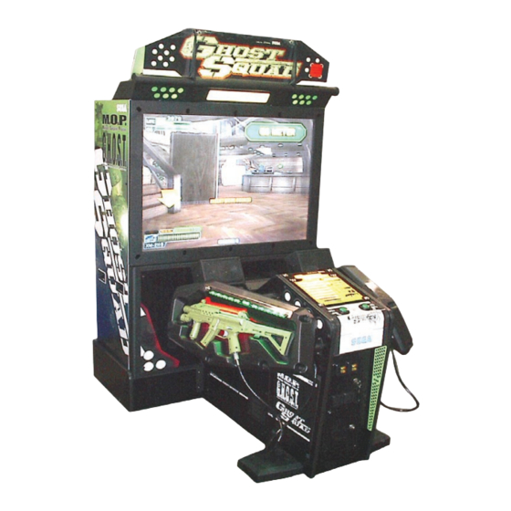
4. NAME OF PARTS BILLBOARD 50 TYPE PROJECTION DISPLAY IC CARD UNIT COIN CHUTE DOOR PTV BASE CASHBOX DOOR GUN CONTROLLER MAIN CABLINET AC UNIT FIG. 4 TABLE 4 Width × Depth × Height Weight 88.19 in × 21.9 in × 65.7 in 220.4 lb PTV BASE 47.2 in ×... -
Page 17: Accessories
5. ACCESSORIES When transporting the machine, make sure that the following parts are supplied. TABLE 5 a ACCESSORIES DESCRIPTION OWNERS MANUAL KEY MASTER 220-5576 (2) Part No.(Qty.) 4201-6831-01 For opening/closing For the CASHBOX DOOR Note the doors Figures NOTE: Parts not labeled with part numbers are as yet unregistered or cannot be registered. - Page 18 HOW TO USE THE CHIHIRO BOARD CARTON BOX STOP Replacement or repair of the Game Board (Chihiro) for this product should be under- taken at the appropriate repair center. Be sure to follow the specifications below when IMPORTANT! requesting repairs/sending the board to the repair center. Not following the specifications may result in the board not being accepted or in extra charges being made.
- Page 19 FIG. 5 a FIG. 5 b www.sauservice.com...
- Page 20 The following Table 5b lists the parts that had been separately packed when the product was shipped from the factory but are necessary when you use the product. These parts will be mounted on the product when installing and assembling it. TABLE 5 b GD SOFT KIT CTF KEY CHIP (1)
- Page 21 The following Table 5c lists the parts that are separately marketed but are necessary when booting this product's software. When having unpacked the shipping crate, make sure that all the parts in this Table 5c are in the crate. If not so, contact where you have obtained the product. TABLE 5 c (XKT-0833 : GD-ROM DRIVE KIT) GD-ROM DRIVE GD-ROM DRIVE CARTON BOX...
- Page 22 HOW TO USE THE CARTON BOX (GD-ROM DRIVE) STOP When you want to order for replacing or repairing service of the GD-ROM drive that is used by the product, pack it in a carton box as instructed below, and then deliver the IMPORTANT! carton box to a service agent.
-
Page 23: Assembly And Installation
6. ASSEMBLY AND INSTALLATION ● Perform assembly work by following the procedure herein stated. Failing to comply with the instructions can cause electric shock hazard. WARNING! ● Perform assembling as per this manual. Since this is a complex machine, erroneous assembling can cause an electric shock, machine damage and or not functioning as per specified performance. - Page 24 When carrying out the assembling and installation, follow the following 9-item sequence. ASSEMBLING THE BILLBOARD ASSEMBLING THE PTV ASSEMBLING THE CABINET SECURING IN PLACE(ADJUSTER TUNING) ATTACHING THE FLUORESCENT LIGHTS AND LAMPS INSTALLING THE GD-ROM DRIVE(SETTING THE GD-ROM DISC) POWER SUPPLY AND EARTH CONNECTION TURNING THE POWER ON ASSEMBLY CHECK The master key (accessories) in addition to the tools such as a Phillips type screwdriver, wrench, socket...
- Page 25 ASSEMBLING THE BILLBOARD ● Undo the 2 truss screws, and remove the pop bracket. POP BRACKET TRUSS SCREW (2), black M4×8 PHOTO 6. 1 a ● Undo the 3 truss screws, and remove the pop holder. TRUSS SCREW (3), black M4×8 POP HOLDER PHOTO 6.
- Page 26 ● Attach the assembled billboard pop using the 2 truss screws. TRUSS SCREW (2), black M4×8 PHOTO 6. 1 d www.sauservice.com...
- Page 27 ASSEMBLING THE PTV ● By using 2 Flat Head screws, secure the 2 Mask Bracket Uppers to the PTV ceiling. ● Secure the Mask Bracket Lower to the front of PTV with 4 screws. FLAT HEAD SCREW (2 each) M4×8 MASK BRACKET UPPER MASK BRACKET LOWER SCREW (4), black...
- Page 28 Install Mask to the PTV front. Install the Mask in a manner hooking up to both 2 Mask ● Bracket Uppers and the Mask Bracket Lower. Simultaneously insert the projections of the Mask into the square holes in the PTV screen left and right. Secure the Mask by fastening a screw for each from both sides of PTV.
- Page 29 ASSEMBLING THE CABINET Move the PTV to the back of the PTV base. ● Put the PTV on the PTV base. To do this, you will need at least 4 people to lift the PTV, and another per- ● son to hold the PTV base to stop it from moving. Lower the PTV until it touches the supports. Take care not to damage any wiring during this step.
- Page 30 Have 2 people lift the billboard and place it on the PTV. Lower the ● billboard so that the two mask bracket uppers that were attached in step 2 fit into the 2 rectangular holes in the billboard base plate, and push the billboard towards the PTV screen.
- Page 31 Connect the internal billboard connector to ● the connector in the PTV ceiling. BILLBOARD INTERNAL CONNECTOR PTV CEILING CONNECTOR PHOTO 6. 3 e Attach the connector lid using the single truss screw. ● Bring the main cabinet next to the PTV. ●...
- Page 32 Tighten the 2 hexagon bolts on ● each of the left and right brackets of the main cabinet to affix the cabinet. HEXAGON BOLT (2 ea), black w/spring washer, flat washer used BRACKET PHOTO 6. 3 h Attach the joint bracket uppers to the left and right sides of the joint between the main cabinet and the ●...
- Page 33 SECURING IN PLACE (ADJUSTER TUNING) Make sure that all of the adjusters are in contact with the floor. If they are not, the cabi- net can move and cause an accident. WARNING! This product has 8 casters (4 for PTV Base, 4 for MAIN CABINET) and 6 Adjusters (4 for PTV Base, 2 for MAIN CABINET).
- Page 34 ATTACHING THE FLUORESCENT LIGHTS AND LAMPS Fluorescent Light Undo the 4 screws using the supplied L- ● wrench, and remove the instruction panel. INSTRUCTION PANEL HEXAGON SOCKET SCREW (4) M5×10, special washer used PHOTO 6. 5 a Attach the globe-shaped fluorescent light. ●...
- Page 35 Halogen Lamp Undo the 4 truss screws, and remove the lamp lid. ● TRUSS SCREW (2), black M4×20 LAMP LID TRUSS SCREW (2), black M4×8 PHOTO 6. 5 c Attach the halogen lamp. ● HALOGEN LAMP 40W 390-6732-40N PHOTO 6. 5 d Reattach the lamp lid in its original position using the 4 screws.
- Page 36 INSTALLING THE GD-ROM DRIVE (SETTING THE GD-ROM DISC) STOP ● Carefully handle the GD-ROM drive so as not to contaminate the disc and the read- out lens with stains and dust particles. IMPORTANT! ● Do not continue to use the scratched GD-ROM disc. The scratched GD-ROM disc may cause the system to malfunction.
- Page 37 Use the 4 tapping screws to fix the GD-ROM drive bracket onto the GD-ROM drive. Be careful about a ● fixing direction. TAPPING SCREW (4) 4×8 FIG. 6. 6 a Remove the 1 truss head screw that ● fixes the GD-ROM drive lid (DISC LID).
- Page 38 Set the GD-ROM disc onto the GD-ROM drive with its labeled side facing upward. ● Return the lid to its original place, and fix it with 1 truss head screw. Be careful not to fasten the screw ● too tightly. PHOTO 6.
- Page 39 Unplug the 3 connectors. ● CONNECTOR (3) PHOTO 6. 6 f Undo the fixing screws on the left and right ● sides of the D-SUB connector that connects to the side of the game board on the ASSY MAIN BD. Unplug the USB connector. USB CONNECTOR D-SUB CONNECTOR PHOTO 6.
- Page 40 Take out the ASSY MAIN BD from ● the main cabinet. Be careful not to damage the wires in this instance. ASSY MAIN BD PHOTO 6. 6 i Place the ASSY MAIN BD on a flat horizontal surface. ● Using the 4 screws, fix the GD- ●...
- Page 41 Insert Key Chip straight into the hole on the Media Board side of upper part of the Game Board. ● Be sure to check the alignment of the key chip and push it all the way in. KEY CHIP PHOTO 6. 6 l Affix the enclosed stickers to the Game Board.
- Page 42 POWER SUPPLY AND EARTH CONNECTION ● Be sure to independently use the power supply socket outlet equipped with an Earth Leakage Breaker. Using a power supply without an Earth Leakage Breaker can WARNING! cause a fire when electric leakage occurs. ●...
- Page 43 Connect one end of the earth wire to the AC Unit ● Connect the Earth Wire earth terminal, and the other end to the indoor earth to the Earth Terminal. terminal. The AC Unit earth terminal has a Bolt and Nut combination.
- Page 44 TURNING THE POWER ON Turn the main switch on the AC unit on to turn the power on. When the power is turned on, the fluores- cent lights in the billboard and instruction panel turn on. A few second later, the system startup screen is displayed, then the waiting screen for customers (advertising screen) is displayed.
- Page 45 ASSEMBLY CHECK In the TEST MODE, ensure that the assembly has been made correctly and IC BD. is satisfactory (refer to Section 9). In the test mode, perform the following test: 9-1 MEMORY TEST When "MEDIA BOARD TEST" is selected from the System Test Mode Menu Screen the Game Board memory is automatically tested.
- Page 46 9-2 C.R.T. TEST C.R.T. TEST 1/2 In the TEST mode menu, selecting C.R.T. TEST allows the screen (on which the pro- jector is tested) to be displayed. Although the projector adjustments have been made at the time of shipment from the factory, make GREEN judgment as to whether an adjustment is needed by watching the test mode screen.
- Page 47 9-4 OUTPUT TEST Select OUTPUT TEST from the menu in the test mode to cause the screen (on which each lamp and wir- ing connections are tested) to appear. Ensure that lamp light up satisfactorily. OUTPUT TEST PLAYER 1 START LAMP PLAYER 2 START LAMP PLAYER 1 HALOGEN LAMP OFF PLAYER 2 HALOGEN LAMP OFF...
- Page 48 THE HOUSE OF THE DEAD 3, U/R type and DX type ● VIRTUA COP 3, U/R type and DX type ● GHOST SQUAD, U/R type and DX type ● Turn the power off. ● Undo the 2 truss screws and remove the side door ●...
- Page 49 The interference prevention wire is connected to the sensor board on the lower right side. ● If multiple units of the same game are installed side by side, make sure that the game units that are connected to the interference prevention wires are arranged so that they alternate with the units that are not connected.
-
Page 50: Precautions When Moving The Machine
7. PRECAUTIONS WHEN MOVING THE MACHINE ● When moving the machine, be sure to pull out the plug from the power supply. Mov- ing the machine with the plug as is inserted can cause the power cord to be damaged WARNING! and could result in a fire and or electric shock. - Page 51 Do not push PTV from the back. Pushing the PTV from the back can cause the PTV to fall down. Push it from the side. Have caster make contact with the floor. FIG. 7 a GRIP PORTION When transporting the product in places with steps or step-like differ- ences in grade, disassemble into each unit before transporting.
- Page 52 Cautions When Transporting the Machine Do not tie machine down using Plastic Parts as an anchor. ● When using straps or tie downs (rope etc), use caution. Use protective material where tie downs contact machine to avoid damage. To keep machine from shifting during transport, be certain all leg adjusters are in contact with the pallet.
-
Page 53: Game Description
8. GAME DESCRIPTION The following explanations apply to the case the product is functioning satisfactorily. Should there be any moves different from the following contents, some sort of faults may have occurred. Immediately look into the cause of the fault and eliminate the cause thereof to ensure satisfactory operation. The fluorescent lights in the billboard and in the instruction panel are always on whenever the power is turned on. - Page 54 ("Only without the IC Card") is explained separately as needed. (1) GAME OUTLINE The player is a member of the special forces unit, "Ghost Squad", out to suppress vicious terrorists. Each mission contains multiple routes, allowing the player to choose how to proceed. Special events occur throughout the game depending on the route chosen, such as securing hostages or providing friendly cover fire.
- Page 55 (3) CHARACTERS ● Alpha Unit The Alpha Unit are the main characters in the game and are young hot-shot members of "Ghost Squad", an unofficial unit of the anti-terrorist group, "M.O.P." (Multiple-Operation-Program) ● Fellow M.O.P. Members The Commander provides radio backup and pertinent advice to the Alpha Unit.
- Page 56 (4) GAME FLOW AND ON-SCREEN DISPLAY ● Card Insertion Screen [Only with the IC Card] The IC Card Insertion Screen is displayed when starting a game. Insert an IC Card into the card slot to read stored data. To play a game without using an IC Card, select the "Start game without card." panel. IC Card updates are also handled on this screen.
- Page 57 ● Customize Screen [Only with the IC Card] On the Customize Screen, weapons and costumes can be changed. With sufficient game progress, name change and screen display type selection also become available. Customize Screen (A)(B) Item Scroll Buttons Scrolls through costume type indicators. Rapid scrolling is possible by keeping it held down.
- Page 58 ● Customize Screen [Only without the IC Card] Starting the game without an IC Card will display the following screen and allow weapon and costume selection. ● Name Entry Screen When starting a game with a new IC Card, the Name Entry Screen is first displayed. A name chosen once can later be changed on the Customize Screen.
- Page 59 ● Gun Controller Explanation Screen Exiting the Customize Menu plays the demo explaining how to use the gun controller. This explains the shooting stance, and how to use the SHOT SELECTOR and ACTION button. It is possible to skip this explanation with the START button. Gun Controller Explanation Screen ●...
- Page 60 ● Mission Select Screen On this screen, the player selects which mission to play from 3 available missions. Playing one mission all the way to the end displays this screen once again, allowing the player to select another mission. A mission played once cannot be played again in the same game. Mission Achievement Mission Level...
- Page 61 (5) Mission Level : Level of the current mission. (6) Terrorist : Find and suppress! (7) Fellow Troops : Members of the "Ghost Squad". (8) Correspondence : Support requests from fellow troops, or advice from the Commander appears here. (9) Firing Mode : Selectable firing modes and the currently selected firing mode...
- Page 62 ● Mission Results Screen [Only with the IC Card] After either successfully completing a single mission or dying partway, the Mission Result Screen is displayed. Mission information, including the route taken or event results, can be confirmed on this screen. This screen also displays a notification if the Mission Level has increased.
- Page 63 (5) GAME RULES AND GAMEPLAY Life During play, the player's life is displayed at the top part of the screen. Life is diminished by enemy attack or accidental fire on hostages. Once the player's life runs out, play stops. The amount of life to start a game with can be configured in Test Mode settings. Changing life settings will not affect the length of the life gauge.
- Page 64 E-Marker When discovered, the terrorists commence fire upon the player. However, not all shots result in injury. An "E-Marker" will be displayed on any enemy whose shots will inflict damage, serving as a warning to the player. When under fire from multiple enemies, first defeating enemies marked with an E-Marker should help the player avoid damage.
- Page 65 The number of selectable tactics will increase along with the Mission Level. Also, a "NEW" label will be displayed on any newly appearing tactics panels. [When no IC Card is being used, the number of Tactics Selection panels will not increase.] Mission level-up Initially only one route Branching routes...
- Page 66 Auxiliary Items Auxiliary items appear in certain situations during the game. There are two types of auxiliary items—items that are put to use and disappear immediately after picking up, and those that are stocked and continue to be effective over time. The latter type can be used only one at a time.
- Page 67 Costumes This game has 14 different costumes. Initially only 2 are available ("GHOST SQUAD" and "JUNGLE"), but that number increases with further play. The chosen costume can be viewed during in-game cut scenes. Costumes have no direct effect on damage, score, or other game content.
- Page 68 Mid-game Entry It is possible for an additional player to join later, even if a player is in the middle of play. If the necessary number of credits has been inserted, a message (as shown below) is displayed on the bottom part of the screen.
- Page 69 (6) IC CARDS [ONLY WITH THE IC CARD] ● Number of Uses The number of uses per IC Card is 100. This number includes expenditure for starting or continuing games. An IC Card with 0 remaining uses cannot be used to start a game. However, if the remaining uses reaches 0 during play, it is possible to continue a game.
-
Page 70: Explanation Of Test And Data Display
9. EXPLANATION OF TEST AND DATA DISPLAY By operating the switch unit, periodically perform the tests and data check. When installing the machine initially or collecting cash, or when the machine does not function correctly, perform checking in accordance with the explanations given in this section. The following shows tests and modes that should be utilized as applicable. - Page 71 9-1 SWITCH UNIT AND COIN METER Never touch places other than those specified. Touching places not specified can cause electric shock and short circuit accidents. WARNING! STOP ● Adjust the sound to the optimum volume, taking into consideration the environmental requirements of the installation location. IMPORTANT! ●...
- Page 72 9-2 SYSTEM TEST MODE STOP Any settings that are changed by users during TEST MODE are saved upon exiting ● TEST MODE with the EXIT command in the SYSTEM MENU. If the unit is IMPORTANT! powered off prior to exiting, changes to settings will not take effect. You may not enter GAME TEST MODE while the unit is reading from or checking ●...
- Page 73 B. MEDIA BOARD TEST STOP Powering off the system during the MEDIA BOARD TEST with a DIMM BOARD will erase the game programme data. It may be necessary to reload the data. IMPORTANT! Always wait for the test to complete before attempting to exit. MEDIA BOARD TEST is used to check the memory and IC on the MEDIA BOARD connected to the Chihiro.
- Page 74 C. SYSTEM INFORMATION Use SYSTEM INFORMATION to check version and other information for system programmes. Screens may differ depending on the type of MEDIA BOARD connected to the unit. ● The following is the SYSTEM INFORMATION screen for a unit with a DIMM BOARD. SYSTEM INFORMATION MAIN BOARD REGION...
- Page 75 D. JVS TEST JVS TEST is used to verify the specs of the I/O BOARD connected to the Chihiro and to run input tests. I/O BOARD specs are displayed initially. Screens may differ depending on the type of I/O BOARD connected to the unit. JVS TEST INPUT TEST NEXT NODE...
- Page 76 INPUT TEST Screen JVS TEST INPUT TEST NODE SYSTEM PLAYER 1 0000 PLAYER 2 0000 COIN 1 0000 COIN 2 0000 ANALOG 1 0000 ANALOG 2 0000 ANALOG 3 0000 ANALOG 4 0000 ANALOG 5 0000 ANALOG 6 0000 ANALOG 7 0000 ANALOG 8 0000 PRESS TEST AND SERVICE BUTTON TO EXIT ●...
- Page 77 E. SOUND TEST Use SOUND TEST to test sound output and to select the stereo/mono/surround setting. SOUND TEST OUTPUT TYPE STEREO RIGHT SPEAKER LEFT SPEAKER →EXIT SELECT WITH SERVICE BUTTON AND PRESS TEST BUTTON ● Use the SERVICE Button to move the cursor to the desired test item. ●...
- Page 78 F. C.R.T. TEST Use the C.R.T. TEST to adjust monitor colours and verify screen size. COLOUR CHECK Screen ● Monitor COLOUR CHECK screen is displayed initially. Each of the colours (red, green and blue) is darkest at the far left and gets progressively lighter (32 steps) towards the right.
- Page 79 G. COIN ASSIGNMENTS Use COIN ASSIGNMENTS to set the credit rate for each coin inserted. ● Use the SERVICE Button to move the cursor to the desired test item. ● Press the TEST Button to change the setting or to open the detailed settings. ●...
- Page 80 COIN TO CREDIT RATE Set the CREDIT RATE for each coin inserted. The "x COIN(S) COUNT AS y CREDIT(S)" setting indicates that "Inserting x coins equals y credits". Set this to "FREE PLAY" to allow game play without credits. When (A) COIN CHUTE TYPE is set to "COMMON", COIN CHUTE #2 settings are restricted to some extent by the settings for COIN CHUTE #1.
- Page 81 GAME COST SETTING Use this mode to set the number of credits required to start a game. Screens may differ depending on the game. COIN ASSIGNMENTS GAME COST SETTING 1 CREDIT(S) TO START 1 CREDIT(S) TO CONTINUE →EXIT SELECT WITH SERVICE BUTTON AND PRESS TEST BUTTON Set the number of credits required to start a game.
- Page 82 H. CLOCK SETTING Use CLOCK SETTING to set the Chihiro internal clock. CLOCK SETTING 20XX/XX/XX(XXX) XX:XX:XX YEAR MONTH HOUR MINUTE →EXIT SELECT WITH SERVICE BUTTON AND PRESS TEST BUTTON ● Use the SERVICE Button to move the cursor to the item to be set. ●...
- Page 83 I. NETWORK SETTING (CORE) Use the LAN PORT attached to the Main Board, and carry out the settings necessary for network communication. Note: This function is not available with this product. NETWORK SETTING (CORE) ->REMOTE(C) ENABLE IP ADDRESS(C) ---.---.---.--- SUBNET MASK(C) ---.---.---.--- GATE WAY(C) ---.---.---.---...
- Page 84 J. NETWORK SETTING (MEDIA) Use NETWORK SETTING to establish and test network connections. This is only displayed the following error message screen. • This game does not support network communication connections. NETWORK SETTING(MEDIA) COMMUNICATION ERROR www.sauservice.com...
- Page 85 9-3 GAME TEST MODE STOP When changing the game configuration, changes will not take effect until the Game Test Mode has been completed. Be sure to exit the Game Test Mode properly after configu- IMPORTANT! ration changes. Select ENTER GAME TEST from the System Menu screen to display the Game Test Menu screen as follows.
- Page 86 A. INPUT TEST Select INPUT TEST to display the following screen and check the status of input devices. This test should be used periodically to check that each input device is functioning correctly. INPUT TEST PLAYER TRIGGER ACTION CHANGE CARD IN GUN-X GUN-Y SCREEN...
- Page 87 B. OUTPUT TEST Select OUTPUT TEST to display the following screen and check the status of each lamp. This test should be used periodically to check that the lamps are functioning correctly. Press the SERVICE Button to move the cursor and the TEST Button to select. Displays ON when selected.
- Page 88 C. GAME ASSIGNMENTS Select GAME ASSIGNMENTS to display the current game settings and make changes. GAME ASSIGNMENTS DIFFICULTY NORMAL LIFE REACTION CALIBRATION ADVERTISE SOUND ON CARD -> EXIT SELECT WITH SERVICE BUTTON AND PRESS TEST BUTTON FIG. 9. 3 c GAME ASSIGNMENTS screen Perform the following settings for each item.
- Page 89 D. GUN ADJUSTMENT Select GUN ADJUSTMENT to display the following screen. This screen allows you to adjust the gun using the five calibration targets (TOP, LEFT, CENTER, RIGHT, BOTTOM). Use each target to calibrate as follows. Use the standard gun controller, carefully aim at the correct target and pull the trigger to calibrate the value.
- Page 90 Details for each item are as follows. ● TOP x y: Set the TOP value. The number on the left (x) is the horizontal component, and the number on the right (y) is the vertical component. Aim the controller at the TOP target (circle) and pull the trigger to set the value.
- Page 91 E. CARD READ/WRITE TEST Select CARD READ/WRITE TEST to display the following screen with testing options for the reading and writing of IC Cards. Use this screen regularly to test the functionality of the machine. First, insert an IC Card into the slot, then press the SERVICE button to choose the item for testing. When the cursor is on the desired item, press the TEST Button.
- Page 92 F. CLOSE SETTING Select CLOSE SETTING to display the following screen with a list of store closing time settings. When only 30 minutes is left until the set closing time, it will no longer be possible to use an IC Card to start the game.
- Page 93 G. BOOKKEEPING Select BOOKKEEPING on the Game Test Menu screen to display the three screens of operating status data. Press the TEST Button on the BOOKKEEPING 1/3 and BOOKKEEPING 2/3 screens to move to the second and third (BOOKKEEPING 3/3) screens. Press the TEST Button in the third screen to return to the Game Test Menu Screen.
- Page 94 BOOKKEEPING 2/3 NUMBER OF GAMES NUMBER OF GAME START NUMBER OF GAME JOIN NUMBER OF CONTINUE TOTAL TIME 0D 0H10M49S PLAY TIME 0D 0H 1M55S LONGEST PLAY TIME 0H 1M24S SHORTEST PLAY TIME 0H 0M14S AVERAGE PLAY TIME 0H 0M38S PRESS TEST BUTTON TO CONTINUE FIG.
- Page 95 H. BACKUP DATA CLEAR Select BACKUP DETA CLEAR to clear the contents of BOOKKEEPING, ranking data and coin/credit data. BACKUP DATA CLEAR YES (CLEAR) -> NO (CANCEL) SELECT WITH SERVICE BUTTON AND PRESS TEST BUTTON FIG. 9. 3 h BACKUP DATA CLEAR screen To clear data, use the SERVICE Button to move the cursor to YES (CLEAR) and then press the TEST Button.
-
Page 96: Control Unit (Gun Controller)
10. CONTROL UNIT (GUN CONTROLLER) ● In order to prevent any electric shocks or short circuits, be sure to turn the power off before performing any work that involves touching the interior parts of the product. WARNING! ● Be careful not to damage the wires. Damaged wires may cause electric shocks or short circuits, or present a risk of fire. - Page 97 REPLACING THE MICROSWITCH To replace the Gun Controller's internal components, first separate the left shell (Cover L) and right shell (Cover R). The controller's internal components are mounted on the right shell, so work with the gun lying on its right side. To replace the Shot Selector button microswitch, first remove the Shot Selector button from the right shell.
- Page 98 ● With the right shell lying flat, carefully lift the left shell from the right shell. COVER L COVER R PHOTO 10 b ● Remove the microswitch to be replaced from Cover R. There are a total of three microswitches. MICROSWITCH 509-5080 PHOTO 10 c...
- Page 99 ● Solder the new microswitch in place to reconstruct the gun controller. When performing this step, verify the points listed below before reattaching Cover L and Cover R. ●The wires and connectors are laid out correctly in Cover R. ●The bearing holder is securely in place when the pad assembly spring is compressed. ●The selector is laid out horizontally.
- Page 100 ● Operate the TRIGGER, SHOT SELECTOR and ACTION buttons to make sure that the microswitches turn ON/OFF correctly. SHOT SELECTOR ACTION BUTTON TRIGGER FIG. 10 c ● After replacement, perform an INPUT TEST, referring to the instructions in "Game Test Mode". www.sauservice.com...
- Page 101 REPLACING THE SENSOR UNIT ● Follow instructions of "Replacing the Microswitch" to remove the cover L. ● Remove the connector to replace the sensor unit. SENSOR UNIT JPT-2030 Remove the connector. PHOTO 10 f ● Refer to the previous item, then attach COVER R while being careful of each of the parts. ●...
- Page 102 ● Remove the 2P connector, wire and 4 screws to take off the solenoid assembly. Remove the connector. SOLENOID ASSEMBLY SCREW (4) WIRE M3×6, w/spring washer PHOTO 10 g ● Remove the 8 screws and replace the solenoid. SCREW (8) M3×6, w/spring washer SOLENOID PHOTO 10 h...
-
Page 103: C Card Unit
11. IC CARD UNIT ● When working with the product, be sure to turn the power off. Working with the power on can cause an electric shock or short circuit accident. WARNING! ● Be careful not to damage the wires. Damaged wires may cause electric shock, short circuit or present a risk of fire. - Page 104 ● Turn the power off. ● Unlock the coin chute door using the master key. COIN CHUTE DOOR PHOTO 11. 1 a ● Lift the control panel by pulling it up while you pull on the internal ceiling flap. Make sure that the stay remains hooked in place.
- Page 105 ● Disconnect the single connector. Disconnect the connector. PHOTO 11. 1 c ● Remove the 2 truss screws. TRUSS SCREW (2), black M4×8 PHOTO 11. 1 d ● Pull the IC card unit towards you to remove IC CARD UNIT PHOTO 11.
- Page 106 ● Undo the 2 screws and remove the sensor bracket. SENSOR BRACKET SCREW (2) M4×10, w/flat & spring washers PHOTO 11. 1 f ● Undo the 4 screws, and remove the RW guide upper. SCREW (4) RW GUIDE UPPER M4×10, w/flat & spring washers PHOTO 11.
- Page 107 ● Wipe any dirt off the surfaces that touch the IC cards. Clear any foreign matter that has collected in the unit. The roller is a small component, so take the same precautions that you would for the screws to avoid losing it.
- Page 108 ● Attach the RW guide upper by inserting the push rod from the RW guide lower into the hole in the RW guide upper. Take care not to lose the roller at this time. RW GUIDE LOWER PUSH ROD RW GUIDE UPPER PHOTO 11.
- Page 109 11-2 FIXING JAMMED CARDS If an IC card becomes jammed, push out the IC card using your fingertips through the square hold in the RW guide. PHOTO 11. 2 a If an IC card becomes jammed, it may be due to one of the following various reasons. •...
-
Page 110: Projector
12. PROJECTOR Since the Projector has been adjusted at the time of shipment, avoid making further adjustments without good reason. CAUTION! STOP The Projector is subject to color deviation due to Convergence deviation caused by the geomagnetism at the installation location and peripheral magnetic field. After the IMPORTANT! installation of machine, and before commencing operation, check for Convergence deviation and if deviated, make adjustments. - Page 111 12-2 PROJECTOR ADJUSTMENT SETTING THE INTERFACE STOP In this product, set to INPUT LEVEL: 0.7 V and IMPEDANCE: 75Ω. Failure to observe this can cause CRT membrane to burn or Shutdown device to function resulting IMPORTANT! in power off. The Projector's Connector Panel contains the Interface setting SW. REMOTE CONTROL BUTTONS When adjusting the Projector, direct the Remote Control's light emitting portion towards the Projector Screen.
- Page 112 AUTOMATIC COLOR MATCHING The Projector may be subject to color deviations affected by earth magnetism, the building steel frames, etc. When the Projector is initially installed or the Projector's installation position is changed, have the color matching performed automatically. ● Keep pressing the P button (red) for approximately 3 seconds to have the ensuing movements performed automatically.
- Page 113 ADJUSTING THE ON-SCREEN CONTRAST Although the on-screen picture quality has been adjusted at the time of shipment from the factory, the on-screen contrast can be readjusted if desired. When the Game Board is replaced, readjustment may be necessary. Changing the CONTRAST causes the light and shade of the on-screen images to be changed. ▲...
- Page 114 ADJUSTING THE SCREEN BRIGHTNESS Although the on-screen picture quality has been adjusted at the time of shipment from the factory, readjustment can be made if desired. When the Game Board is replaced, readjustment may be necessary. Changing the BRIGHTNESS causes the brightness of the on-screen images of black portions to be changed.
- Page 115 ADJUSTING THE ON-SCREEN DISPLAY POSITION Although the on-screen display position (H. POSI, V. POSI) has been adjusted at the time of shipment from the factory, readjustment can be made if desired. When the Game Board is replaced, readjustments may be necessary. ▲...
- Page 116 ADJUSTING THE SCREEN SIZE Although the on-screen size (H. SIZE, V. SIZE) has been adjusted at the time of shipment from the factory, readjustment can be made if desired. When the Game Board is replaced, readjustments may be necessary. ▲ ▼...
- Page 117 CONVERGENCE ADJUSTMENT (manual color matching) To avoid circuitry malfunctioning due to electrical load increase, never utilize CONVERGENCE ADJUSTMENT (Line Convergence Adjustment in particular) for CAUTION! adjusting screen size changes. There is no means to restore the Convergence Adjustment data once stored, to its original state.
- Page 118 STATIC CONVERGENCE ADJUSTMENT In the STATIC CONVERGENCE adjustment, each of red and blue images is comprehensively moved to and superimposed on the green color. If automatic color matching function is not sufficiently satisfactory, perform this adjustment. Be sure to perform automatic color matching before starting the above adjustment.
- Page 119 LINE CONVERGENCE ADJUSTMENT In the LINE CONVERGENCE adjustment, the adjustment point of the column line (vertical) or row line (horizontal) is comprehensively moved for color matching. It is convenient to utilize this adjustment when the color of the column line or row line is uniformly deviated. (1) Keep pressing the TEST button for approximately 3 The screen changes to ADJUST MODE from the Game Board mode and displays the green test...
-
Page 120: Coin Selector
13. COIN SELECTOR HANDLING THE COIN JAM If the coin is not rejected when the REJECT button is pressed, open the coin chute door and open the selector gate. After removing the jammed coin, put a normal coin in and check to see that the selector correctly functions. -
Page 121: Replacing The Fluorescent Lights And Lamps
14. REPLACING THE FLUORESCENT LIGHTS AND LAMPS ● When performing work, be sure to turn power off. Working with power on can cause electric shock and short circuit hazards. WARNING! ● The Fluorescent Lamp, when it gets hot, can cause burn. Be very careful when replacing the Fluorescent Lamp. - Page 122 ●Remove the acrylic panel. ACRYLIC PANEL PHOTO 14 b ● Replace the fluorescent light. FLUORESCENT LIGHT PHOTO 14 c www.sauservice.com...
- Page 123 Instruction Panel Internal Fluorescent Light ● Turn the power off. ● Undo the 4 screws using the supplied L- wrench, and remove the instruction panel. INSTRUCTION PANEL HEXAGONAL SOCKET SCREWS (4) M5×10, using special washers PHOTO 14 d ● Replace the globe-shaped fluorescent light. GLOBE-SHAPED FLUORESCENT LIGHT 13W 390-6782 PHOTO 14 e...
- Page 124 Halogen Lamp ● Turn the power off. ● Undo the 4 truss screws and remove the lamp lid. TRUSS SCREW (2), black M4×20 LAMP LID TRUSS SCREW (2), black M4×8 PHOTO 14 f ● Replace the halogen lamp. HALOGEN LAMP 40W 390-6732-40N PHOTO 14 g www.sauservice.com...
-
Page 125: Periodic Inspection
15. PERIODIC INSPECTION The items listed below require periodic check and maintenance to retain the performance of this machine and to ensure safe business operation. When handling the control unit, the player will be in direct contact with it . In order to always allow the player to enjoy the game, be sure to clean it regularly. - Page 126 CLEANING THE CABINET SURFACES When the cabinet surfaces become dirty, remove stains with a soft cloth soaked in water or diluted (with water) chemical detergent and then wrung dry. To avoid damaging the finish, do not use such solvents as thinner, benzene, etc.
-
Page 127: Troubleshooting
16. TROUBLESHOOTING 16-1 PROBLEMS NOT INVOLVING THE GAME BOARD In case a problem occurs, first check wiring connector connections. ● In order to prevent electric shock and short circuit, be sure to turn power off before performing work. WARNING! ● Be careful not to damage the wires. Damaged wires may cause electric shock or short circuit or present a fire risk. - Page 128 TABLE 16.1b PROBLEMS CAUSE COUNTERMEASURES No sound is emit- Sound volume adjustment is not ap- Adjust sound volume (see Sec. 9). ted. propriate. Board and Amplifier Perform the sound test and confirm (see malfunctioning Sec. 9-2). Control Unit sight- Sights are not aligned due to changes Perform sighting adjustment in the test ing is not satisfac- in the surrounding environment.
- Page 129 REPLACING THE LED BD In case two of LED's do not emit light, failure and malfunctioning may be considered. Replace in the following procedure. When removing surface soils, also use the following procedure. If the light emission from the 2 LED's can not be seen, replace. / FIG.
- Page 130 REPLACING THE FUSE ● Fuse replacements other than those specified can cause accidents and are strictly forbidden. In case fuse replacements other than those stated in this manual are WARNING! necessary, contact where you purchased the product from for inquiries regarding this matter.
- Page 131 ● Replace the fuse. There are 200mA (for the sensors) and 2A (for the solenoids) fuses. FUSE4: 250V 2A(514-5086-2000) 2P gun solenoid FUSE3: 250V 200mA(514-5086-200) 2P gun sensor FUSE1: 250V 200mA(514-5086-200) 1P gun sensor FUSE2: 250V 2A(514-5086-2000) 1P gun solenoid PHOTO 16.
- Page 132 16-2 ERROR CODES ● If an error code is displayed, have a Location's Maintenance Man or Serviceman resolve it. If someone without specialized or technical knowledge attempts to rec- WARNING! tify the problem, electric shock, short circuits or fire may result. If there is no store maintenance person or technician available, turn the power OFF immediately, and contact your retailer or the office listed in this manual.
- Page 133 Error 11 [DISPLAY] Error 11 JVS I/O board is not connected to main board. [CAUSE] (1) I/O BOARD is not connected. (2) Unreliable connection between MAIN BOARD and I/O BOARD. [COUNTERMEASURES] (1) Connect the I/O BOARD to the MAIN BOARD. Verify that the power cable is connected to I/O BOARD.
- Page 134 Error 24 [DISPLAY] Error 24 GD-ROM is not found. [CAUSE] GD-ROM disc is not found. [COUNTERMEASURES] Insert the GD-ROM disc correctly. Verify that the disc is a Chihiro GD-ROM disc. Check the GD-ROM disc for scratches, dust or dirt. Error 25 [DISPLAY] Error 25 Cannot access GD-ROM drive.
- Page 135 Error 32 [DISPLAY] Error 32 DIMM memory is not enough. [CAUSE] (1) Insufficient DIMM MEMORY on DIMM MEDIA BOARD. (2) DIMM MEMORY is not connected securely. [COUNTERMEASURES] (1) Provide a suitable amount of DIMM MEMORY for the software. (2) Verify that the DIMM MEMORY is connected securely to the DIMM BOARD.
-
Page 136: Game Board
17. GAME BOARD ● In order to prevent electric shock and short circuit hazards, be sure to turn power off before performing work. ● Be careful not to damage the wires. Damaged wires may cause electric shock or short circuit or present a fire risk. ●... - Page 137 ● Disconnect the single connector that connects the wires in the cabinet to the ASSY MAIN BD in the main cabinet. CONNECTOR (1) PHOTO 17. 1 b ● Unplug the 3 connectors. CONNECTOR (3) PHOTO 17. 1 c ● Unscrew and remove the screws that fix the left and right sides of the D-SUB connector that connects to the side of the Chihiro board.
- Page 138 ● Remove the 2 screws that fix the base (wood) of the ASSY MAIN WING SCREW M4×30, flat washer used PHOTO 17. 1 e ● Extract the ASSY MAIN BD from the cabinet with the Chihiro Board attached. At this time, be careful not to damage the wiring.
- Page 139 ● Unplug all connectors connected to the Unplug all connectors. Chihiro Board. Unplug the GD Cable connector on the side of the Media Board on the upper part of the Chihiro Board. PHOTO 17. 1 g ● Unplug the AVIP Cable connected to the Chihiro Board.
- Page 140 REMOVING THE GD-ROM DRIVE Take out the ASSY MAIN BD from the main cabinet; and then remove the GD-ROM drive from the ASSY MAIN BD as follows: ● Carry out the "Removing the Game Board" procedures and remove the ASSY MAIN BD from the cabinet.
- Page 141 17-2 COMPOSITION OF THE GAME BOARD STOP Once the Chihiro Board has the Key Chip inserted, it is this product's specialized Game Board. IMPORTANT! ASSY CASE BOX CTF EXP(843-0012D-02) FIG. 17. 2 a DIP SW SETTING Use this product with the DIP SW settings shown in the figure below. FIG.
- Page 142 17-3 REPLACING THE MAIN BOARD BATTERY ● To prevent overheating, explosion, or fire: • Do not recharge, disassemble, heat, incinerate, or short the battery. WARNING! • Do not allow the battery to come into direct contact with metallic objects or other batteries.
- Page 143 17-4 REPLACING THE MEDIA BOARD BATTERY PACK Prohibitions and Cautions to Handle the Battery Pack Be careful when handling the battery pack. We bear no responsibility for problems caused by handling clearly contrary to the content of this manual. ● Do not disassemble the battery pack and the batteries. If you should fail to observe this instruction, the internal wires and/or protective WARNING! devices may be damaged;...
- Page 144 ● Do not tightly seal the battery pack when installing it onto an external device. Flammable gas is generated from the battery when its safety mechanism has WARNING! functioned. If you should fail to observe the above-described instruction, sparks from motors, switches, etc. may cause the gas to fire. Therefore, install the battery pack so that the gas can be quickly released from the external device.
- Page 145 If the GD-ROM read time becomes excessively long, it is likely that the Media Board battery pack life if running low. No battery pack charger is available. Follow the procedure to replace the battery pack. ● Remove 4 screws from the upper face of the board. ●...
-
Page 146: Design Related Parts
18. DESIGN RELATED PARTS For the Warning Display stickers, refer to Section 1. www.sauservice.com... - Page 147 19. DESIGN RELATED PARTS 1 TOP ASSY CTF DX 2 CTF-0500 3 CTF-0510 ASSY PTV PTV W/STICKER CTF 4 CTF-0550 7 CTF-0660 ASSY BILLBOARD DX ASSY SUB PTV BASE 8 CTF-0670 5 CTF-0600 AC UNIT ASSY FRONT PANEL 6 CTF-0650 28 CTF-4200 ASSY PTV BASE ASSY XFMR 100V AREA...
- Page 148 TOP ASSY CTF DX (D-1/2) www.sauservice.com...
- Page 150 ASSY PTV (CTF-0500) (D-1/2) www.sauservice.com...
- Page 151 ASSY PTV (CTF-0500) (D-2/2) ITEM NO. PART NO. DESCRIPTION NOTE CTF-0510 PTV W/STICKER CTF CTF-0550 ASSY BILLBOARD DX CTF-0600 ASSY FRONT PANEL CTF-0650 ASSY PTV BASE SPY-0530 ASSY MASK FRQ-1114 MASK BRKT LOWER SMB-1501 MASK BRKT LOWER DYN-0501 PANEL MOUNT BRKT L DYN-0502 PANEL MOUNT BRKT R 000-T00520-0B...
- Page 152 PTV W/STICKER CTF (CTF-0510) ITEM NO. PART NO. DESCRIPTION NOTE CTF-0511 STICKER PTV SIDE L CTF-0512 STICKER PTV SIDE R 200-5788-31 PROJECTION DSPL T 50 TYPE 31K www.sauservice.com...
- Page 153 ASSY BILLBOARD DX (CTF-0500) (D-1/2) www.sauservice.com...
- Page 154 ASSY BILLBOARD DX (CTF-0500) (D-2/2) ITEM NO. PART NO. DESCRIPTION NOTE CTF-0551 BILLBOARD BOX CTF-0552 BILLBOARD STAY CTF-0553 BILLBOARD STAY HOLDER CTF-0554 CONNECTOR LID CTF-0555 BILLBOARD PLATE CTF-0556 BILLBOARD FRONT PLATE CTF-0557 BILLBOARD LID CTF-0558 BILLBOARD POP CTF-0559 BILLBOARD FL BRKT CTF-0561 FRONT PLATE SASH CTF-0562...
- Page 155 ASSY FRONT PANEL (CTF-0600) ITEM NO. PART NO. DESCRIPTION NOTE CTF-0601 FRONT PANAL CTF-0602 PANEL BRKT UPPER CTF-0603 PANEL BRKT LOWER EZT-0603 SIDE BRKT CTF-0604 STICKER FRONT PANEL L CTF-0605 STICKER FRONT PANEL R 050-F00500 FLG NUT M5 068-552016 FLT WSHR 5.5-20X1.6 www.sauservice.com...
- Page 156 ASSY PTV BASE (CTF-0650) ITEM NO. PART NO. DESCRIPTION NOTE CTF-0660 ASST SYB PTV BASE CTF-0670 AC UNIT 000-T00420-0B M SCR TH BLK M4X20 000-P00430-S M SCR PH W/S M4X20 068-441616 FLT WSHR 4.4-16X1.6 CTF-4200 ASSY XFMR 100V AREA <AC 110-120V AREA> www.sauservice.com...
- Page 157 ASSY SUB PTV BASE (CTF-0660) (D-1/2) www.sauservice.com...
- Page 158 ASSY SUB PTV BASE (CTF-0660) (D-2/2) ITEM NO. PART NO. DESCRIPTION NOTE CTF-0661 PTV BASE CTF-0662 BASE NUT BRKT SCR-1008 NUT PLATE FOR CASTER ARC-1006 LEG BRACKET 117-5233 PLATE LEG BRACKET BLACK 253-5460-01 AIR VENT BLACK 601-5699X LEG ADJUSTER BOLT M16X75 601-6224 CASTER 75 601-9377...
- Page 159 ASSY SUB PTV BASE (CTF-0670) (D-1/2) www.sauservice.com...
- Page 160 ASSY SUB PTV BASE (CTF-0670) (D-2/2) ITEM NO. PART NO. DESCRIPTION NOTE FZR-1051 AC BRKT 421-7468-02 STICKER C.P W/PIC 421-8202 STICKER EARTH MARK 270-5115 NOISE FILTER 15A GT-215J 450-5134 MAGNET CONTACT S-NIOCX 230V <OTHERS> 509-5453-91-V-B SW ROCKER J8 V-B 214-0202 AC INLET PANEL TYPE 512-5046-8000 C.P 8000MA CE UL...
- Page 161 ASSY MASK (SPY-0530) ITEM NO. PART NO. DESCRIPTION NOTE SPY-0531 MASK BASE JPT-1082 IR COVER 838-13145-02 LED BD GUN SENSOR HOD 280-5008 CORD CLAMP 15 050-U00300 U NUT M3 068-330808-PN FLT WSHR PLASTIC 3.3-8X0.8 050-H00400 HEX NUT M4 060-F00400 FLT WSHR M4 060-S00400 SPR WSHR M4 069-000026...
- Page 162 ASSY CABINET DX (CTF-1000) (D-1/2) www.sauservice.com...
- Page 163 ASSY CABINET DX (CTF-1000) (D-2/2) ITEM NO. PART NO. DESCRIPTION NOTE CTF-1100 ASSY SUB CABI DX CTF-1150 IC RW UNIT CTF-1200 ASSY SPEAKER PIPE CTF-1300 ASSY CONTROLLER HOLDER L CTF-1320 ASSY CONTROLLER HOLDER R CTF-2000 ASSY CONTROLLER PANEL CTF-2100 CONTROL UNIT CTF-4000 ASSY MAIN BD CTF-4100...
- Page 164 ASSY SUB CABI DX (CTF-1100) (D-2/4) ITEM NO. PART NO. DESCRIPTION NOTE CTF-1160 SW UNIT CTF-1170 ASSY LATCH STR-1070 FAN UNIT 610-0549-03 METER UNIT SUNGLE YL CTF-1101 CABINET DX CTF-1102 SIDE DOOR L CTF-1103 SIDE DOOR R CTF-1106 FOOT BASE CTF-1107 PIPE SUPPORT A CTF-1108...
- Page 165 ASSY SUB CABI DX (CTF-1100) (D-3/4) ITEM NO. PART NO. DESCRIPTION NOTE 601-5471 CASTER 601-6056-01 CASTER 50 PH 220-5575 CAM LOCK MASTER W/O KEY 220-5574 CAM LOCK W/ KEYS 214-0123 BULB SOCKET E-26 (ES-T250-E26) 214-0199-04 SOCKET E11 W/CONN VL WH 310-5029-F20 SUMITUBE F F 20MM 280-5009-01...
- Page 166 ASSY SUB CABI DX (CTF-1100) (D-4/4) ITEM NO. PART NO. DESCRIPTION NOTE CTF-6001 ASSY WIRE SUBCABI AC CTF-6002 ASSY WIRE SUBCABI DC 600-6972-0100 WIRE HARN EARTH ID5 0100MM 600-6455-02 WIRE HARN C.C DOOR SINGLE CTF-60019 WH AC FAN CTF-60020 WH AC FL LAMP CTF-60034 WH COIN EXT CTF-60039-0120...
- Page 167 ASSY SUB CABI DX (CTF-1100) (D-1/4) www.sauservice.com...
- Page 168 SW UNIT (CTF-1160) ITEM NO. PART NO. DESCRIPTION NOTE CTF-1161 SW PLATE 421-11826 STICKER SW UNIT CTF 838-13739-02 SW BD TFN 000-P00308-W M SCR PH W/FS M3X8 www.sauservice.com...
- Page 169 ASSY LATCH (CTF-1170) (D-1/2) www.sauservice.com...
- Page 170 ASSY LATCH (CTF-1170) (D-2/2) ITEM NO. PART NO. DESCRIPTION NOTE CTF-1171X LATCH CTF-1172 LATCH BRKT CTF-1173 LATCH SPRING L CTF-1174 LATCH SPRING R 065-E00700 E RING 7MM www.sauservice.com...
- Page 171 FAN UNIT (STR-1070) ITEM NO. PART NO. DESCRIPTION NOTE 105-5340-01 FUN BRKT LONG 260-0011-03 AXIAL FLOW FAN AC100V 50-60HZ 601-8543 FAN GUARD 000-P00312-W M SCR PH W/FS M3X12 www.sauservice.com...
- Page 172 METER UNIT SINGLE YL (610-0549-03) ITEM NO. PART NO. DESCRIPTION NOTE OCN-1521 METER BRKT 421-9168-01 STICKER COIN METER 220-5778-01 MAG CNTR 4P MZ674-DC5V-D28 www.sauservice.com...
- Page 173 METER UNIT SINGLE YL (610-0549-03) This is comprised of the following wire harnesses. ASSY drawing is not available. ITEM NO. PART NO. DESCRIPTION NOTE 601-0460 PLASTIC TIE BELT 100 M/M CTF-60018 WH AC EXT FRINT CABI CTF-60037 WH AC EXT2 FRONT CABI CTF-60038 WH EARTH MASK CTF-60039-1720...
- Page 174 IC RW UNIT (CTF-1150) (D-1/2) www.sauservice.com...
- Page 175 IC RW UNIT (CTF-1150) (D-2/2) ITEM NO. PART NO. DESCRIPTION NOTE CTF-1151 RW BASE CTF-1152 CUSHION SPONGE RW TBA-1662 RW GUIDE LOWER TBA-1663 RW GUIDE UPPER CFB-1664 ROLLER CFB-1665 SOL BASE CFB-1666 SENSOR BRKT TBA-1667 LOCK ARM TBA-1668 SHAFT TBA-1669 SHAFT GUIDE 125-5225 TOR SPRING LOCK ARM...
- Page 176 ASSY SPEAKER PIPE (CTF-1200) Attach so that the speakers are on the outside and the bass reflex ducts are on the inside. ITEM NO. PART NO. DESCRIPTION NOTE CTF-1201 JOINT PIPE REAR 130-5228-01 SPEAKER BOX 40OHM 40W 280-5275-SR10 CORD CLAMP SR10 000-P00512-WB M SCR PH W/FS BLK M5X12 012-P00512-0B...
- Page 177 ASSY CONTROLLER HOLDER (CTF-1300) Fastening Torque: : 1.4N•m(14kgf•cm) ITEM NO. PART NO. DESCRIPTION NOTE CTF-1340 ASSY HOLDER LIGHT CTF-1301 CONTROLLER HOLDER L CTF-1302 CONTROLLER HOLDER PLATE L CTF-1303 CONTROLLER HOOK CTF-1002 WASHER CTF FAS-290037 HEX SKT LH CAP SCR SCR STN M5X20 FAS-120031 TAP SCR P-TITE TH BLK 4X16 www.sauservice.com...
- Page 178 ASSY CONTROLLER HOLDER (CTF-1320) Fastening Torque: : 1.4N•m(14kgf•cm) ITEM NO. PART NO. DESCRIPTION NOTE CTF-1340 ASSY HOLDER LIGHT CTF-1321 CONTROLLER HOLDER R CTF-1322 CONTROLLER HOLDER PLATE R CTF-1303 CONTROLLER HOOK CTF-1002 WASHER CTF FAS-290037 HEX SKT LH CAP SCR SCR STN M5X20 FAS-120031 TAP SCR P-TITE TH BLK 4X16 www.sauservice.com...
- Page 179 ASSY HOLDER LIGHT (CTF-1340) (D-1/2) www.sauservice.com...
- Page 180 ASSY HOLDER LIGHT (CTF-1340) (D-2/2) ITEM NO. PART NO. DESCRIPTION NOTE CTF-1341 HOLDER LIGHT COVER CTF-1342 HOLDER LIGHT PLATE CTF-1343 LED BD BRKT 838-14463 LED BAR BD GREEN 280-5247 ONE TOUCH BUSHING 280-5248-5.7 ONE TOUCH COLLAR M3 L=5.7 280-5275-SR10 CORD CLAMP SR10 050-U00300 U NUT M3 060-F00300...
- Page 181 ASSY CONTROL PANEL (CTF-2000) ITEM NO. PART NO. DESCRIPTION NOTE CTF-2001 CONTROL PANEL BASE CTF-2002X CARD ENTRY PLATE CTF-2003 ENTRY PLATE SASH CTF-2004X LOCK BRKT CTF-2005 CUSHION SPONGE CONT PNL CTF-2006-01 STICKER CONTROL PANEL ENG 509-6069 SW PB OBSA-45UM-G-1FLED-G-5V 280-5009-01 CORD CLAMP 21 050-F00400 FLG NUT M4...
- Page 182 CONTROL UNIT (CTF-2100) (D-1/2) www.sauservice.com...
- Page 183 CONTROL UNIT (CTF-2100) (D-2/2) ITEM NO. PART NO. DESCRIPTION NOTE JPT-2030 SENSOR UNIT CTF-2101 COVER L CTF-2102 COVER R CTF-2103 FRONT SIGHT CTF-2104 MAIN TRIGGER CTF-2105 SUB TRIGGER CTF-2106 SELECTOR CTF-2107 SELECTOR HOLDER CTF-2108 SELECTOR JOINT CTF-2109 PAD BASE CTF-2110 BEARING HOLDER CTF-2111 CTF-2112...
- Page 184 SENSOR UNIT (JPT-2030) ITEM NO. PART NO. DESCRIPTION NOTE JPT-2031 SENSOR HOLDER 838-13144 SENSOR BD GUN SENSE 012-P00306 TAP SCR #2 PH 3X6 www.sauservice.com...
- Page 185 ASSY MAIN BD (CTF-4200) ITEM NO. PART NO. DESCRIPTION NOTE CTF-4001 WOODEN BSE MAIN 843-0001D-22 ASSY CASE BOX COM DIMM EXP 400-5443-01 SW REGU FOR CHIHIRO VW 280-5009-01 CORD CLAMP 21 280-0419 HARNESS LUG 270-5117 FERRITE CORE TDK ZCAT3035-1330 000-P00406-W M SCR PH W/FS M4X16 011-F00312 TAP SCR #1 FH 3X12...
- Page 186 ASSY ELEC (CTF-4100) (D-1/2) www.sauservice.com...
- Page 187 ASSY ELEC (CTF-4100) (D-2/2) ITEM NO. PART NO. DESCRIPTION NOTE CTF-4101 WOODEN BASE ELEC 837-13844-02 I/O CONTROL BD 2 W/O 232C DOG 839-1073-01UL SSR BD 2 AC 2A 601-10369 STEREO PWR AMP 47 838-11856-UL CONNECT BD UL 400-5421-03012 SW REGU LCA30S-12 400-4521-07524 SW REGU LCA75S-24 838-14465...
- Page 188 ASSY XFMR 100V AREA (CTF-4200) ITEM NO. PART NO. DESCRIPTION NOTE CTF-0663 TRANS BASE 560-5384 XFMR 100-120V 100V 10A WB 280-5207 HARNESS LUG CC-1005 030-000620-S HEX BLT W/S M6X20 068-652016 FLT WSHR 6.5-20X1.6 011-T03512 TAP SCR TH 3.5X12 CTF-60036 WH AC EXT PTV CABI EXP www.sauservice.com...
- Page 189 ASSY XFMR 200V AREA (CTF-4300) ITEM NO. PART NO. DESCRIPTION NOTE CTF-0663 TRANS BASE 560-5377 PWR XFMR 200-240V 100V 10A CE 280-5207 HARNESS LUG CC-1005 030-000620-S HEX BLT W/S M6X20 068-652016 FLT WSHR 6.5-20X1.6 011-T03512 TAP SCR TH 3.5X12 CTF-60036 WH AC EXT PTV CABI EXP www.sauservice.com...
- Page 190 THIS IS BLANK www.sauservice.com...
- Page 191 20. WIRE COLOR CODE TABLE THE WIRE COLOR CODE is as follow: PINK SKY BLUE BROWN PURPLE LIGHT GREEN Wires other than those of any of the above 5 single colors will be displayed by 2 alphanumeric characters. BLUE YELLOW GREEN WHITE ORANGE...
- Page 192 Warranty Your new Sega Product is covered for a period of 90 days from the date of shipment. This certifies that the Printed Circuit Boards, Power Supplies and Monitor are to be free of defects in workman- ship or materials under normal operating conditions. This also certifies that all Interactive Control Assemblies are to be free from defects in workmanship and materials under normal operating condi- tions.
Need help?
Do you have a question about the Ghost Squad and is the answer not in the manual?
Questions and answers