Table of Contents
Advertisement
1
PRINTING
at
FEBRUARY 2020
Sega Amusements International Limited.
42 Barwell Business Park, Leatherhead Road, Chessington, Surrey, KT9 2NY. United Kingdom.
Telephone: +44 (0) 208 391 8090
Facsimile:
+44 (0) 208 391 8099
mailbox@sega.co.uk
segaarcade.com
Sega Games Co,. Ltd.
1-2-12, Haneda, Ota-ku, Tokyo, 144-8531. Japan.
Telephone: +81-3-5736-7111
Facsimile:
+81-3-6871-7672
sega-games.co.jp
© SEGA
Errors and omissions excepted (E&OE)
OPERATOR AND SERVICE
MANUAL
IMPORTANT
• Before using this product, read this manual carefully to understand the
contents herein stated.
• After reading this manual, be sure to keep it near the product or in a
convenient place for easy reference when necessary.
Advertisement
Table of Contents

Related Manuals for Sega MARIO & SONIC AT THE OLYMPICS GAMES TOKYO 2020


Summary of Contents for Sega MARIO & SONIC AT THE OLYMPICS GAMES TOKYO 2020
- Page 1 PRINTING FEBRUARY 2020 OPERATOR AND SERVICE MANUAL Sega Amusements International Limited. 42 Barwell Business Park, Leatherhead Road, Chessington, Surrey, KT9 2NY. United Kingdom. Telephone: +44 (0) 208 391 8090 Facsimile: +44 (0) 208 391 8099 mailbox@sega.co.uk segaarcade.com Sega Games Co,. Ltd.
- Page 2 BEFORE USING THE PRODUCT, BE SURE TO READ THE FOLLOWING: To maintain safety: To e n s u r e t h e s a f e o p e r a t i o n o f t h i s p r o d u c t , b e s u r e t o r e a d t h e f o l l o w i n g b e f o r e u s a g e : The following instructions are intended for the users, operators and the personnel in charge of the operation of the product.
- Page 3 INSPECTIONS IMMEDIATELY AFTER TRANSPORTING THE PRODUCT TO THE LOCATION Normally, at the time of shipment, SEGA products are in a status allowing for usage immediately after transporting to the location. Nevertheless, an irregular situation may occur during transportation. Before turning on the power, check the following points to ensure that the product has been transported in a satisfactory status: Are there any dented portions or defects (cuts, etc.) on the external surfaces of the cabinet?
- Page 4 Indicates a warning or caution that, if ignored, may result in the mishandling of the product and cause faulty operation or damage to the product. Sega Amusements International Limited. 42 Barwell Business Park, Leatherhead Road, Chessington, Surrey, KT9 2NY. United Kingdom. European Sales: +44 (0) 208 391 8090...
- Page 5 SUPER MARIO Characters © NINTENDO. Trademarks are property of their respective owners. SONIC THE HEDGEHOG characters © SEGA. SEGA, the SEGA logo and Sonic The Hedgehog are either registered trademarks or trademarks of SEGA Holdings Co., Ltd. or its affiliates.
- Page 6 The symbol shown below will be placed on all products manufactured from 13th August 2005, which indicates this product must NOT be disposed of with other normal waste. Upon purchasing any EEE from SEGA Amusements International Ltd. The user accepts responsibility to dispose of their waste equipment by arranging to return it to a designated UK collection point (AATF) or an Approved Exporter (AE) for the correct recycling of waste electrical and electronic equipment.
-
Page 7: Table Of Contents
TABLE OF CONTENTS INTRODUCTION HANDLING PRECAUTIONS PRECAUTIONS REGARDING INSTALLATION 2-1 Before Operation 2-2 Area of Operation PRECAUTIONS REGARDING OPERATION 3-1 Before Operation 3-2 Paying Attention to Customers PARTS DESCRIPTION ACCESSORIES ASSEMBLY AND INSTALLATION 6-1 Installing the Floor 6-2 Installing the Pipes 6-3 Securing the Floor 6-4 Installing the Billboard and Pop Panel 6-5 Components that Change State Upon Power... - Page 8 LAMPS AND LIGHTING 13-1 Coin Door Lamp 13-2 LED Layout PERIODIC INSPECTION TROUBLESHOOTING 15-1 Troubleshooting (No Error) GAME BOARD 16-1 Removing the Game Board 16-2 Composition of the Game Board 16-3 Error Messages 16-4 System Test Mode DESIGN RELATED PARTS PARTS LIST COLOUR CODE SCHEMATIC DIAGRAMS...
-
Page 9: Handling Precautions
SEGA shall not be held responsible for damage, compensation for damage to a third party, caused by specification changes not designated by SEGA. Do not perform any work or change parts not listed in this manual. Doing so may lead to an accident. - Page 10 VIDEO GAME-INDUCED SEIZURES (VGS) AND PHOTOSENSETIVE EPILEPSY (PSE) This SEGA product has warning displays on stickers which outline the risk of epilepticform and photosensetive seizures. These warning displays on stickers are applied close in proximity of the device which may promote symptoms of either video game-induced seizures or epilepsy.
- Page 11 STICKER DISPLAY Inside SUITABLE If you or your child have experienced a convulsive attack, loss of consciousness, etc., due to light stimulus or TV game, or fear that you may experience such symptoms, be very careful of using this machine. ALL AGES If you feel sick whilst playing this game, immediately discontinue use and take a rest.
- Page 12 Earth Label and Earth Brkt WEEE Label Rating Label Rating Label (Distribution BD) 6.3A Sega Amusements International Ltd. 42 Barwell Business Pk Leatherhead Road | Chessington | Surrey | KT9 2NY | Untied Kingdom 3.15A LB1126-3150-250 MODEL: MSJ-0000UK LB1126-3150-250 Rating Label...
-
Page 13: Precautions Regarding Installation
Securing a safe area for operation as described in this manual will ensure safe operation for players and observers. SEGA shall not be held responsible for damage or compensation for damage to a third party, resulting from the failure to observe this instruction. - Page 14 LIMITATIONS OF USAGE Be sure to check the Electrical Specifications. Ensure that this product is compatible with the location's power supply, voltage, and frequency requirements. A label describing Electrical Specifications is attached to the product. Non-compliance with the Electrical Specifications can cause a fire and electric shock.
- Page 15 It can cause generation of heat which in turn may cause a fire hazard. • SEGA shall not be held responsible for damage or compensation for damage to a third party, resulting from the failure to observe this instruction.
- Page 16 Securing a safe area for operation as described in this manual will ensure safe operation for players and observers. SEGA shall not be held responsible for damage or compensation for damage to a third party, resulting from the failure to observe this instruction.
-
Page 17: Before Operation
PRECAUTIONS REGARDING PRODUCT OPERATION In order to prevent accidents and inappropriate behaviour, please check the following before operating the product. BEFORE OPERATION • To ensure maximum safety for the players and the customers, ensure that where the product is operated has sufficient lighting to allow any warnings to be read. - Page 18 • To avoid electric shock, always check each door or service hatch for damage and make sure that they are fitted correctly. Never operate this product with doors or service hatches removed. • Do not place any of the following objects on top of the product, nearby the product or hang them from the ceiling in close proximity to the product as doing so may result in an electric shock, short circuit or damage to parts.
-
Page 19: Paying Attention To Customers
DURING OPERATION (PAYING ATTENTION TO CUSTOMERS) In order to prevent an accident or encourage inappropriate behaviour, the attendant or operator must endeavor to always pay attention to the behaviour of the players and customers. To play this machine involves physical activity undertaken by the player . - Page 20 In order to avoid accidents, check the following before starting the operation: • To ensure maximum safety for the players and the customers, ensure that where the product is operated has sufficient lighting to allow any warnings to be read. Operation under insufficient lighting can cause bodily contact with each other, hitting accident, and/or trouble between customers.
-
Page 21: Parts Description
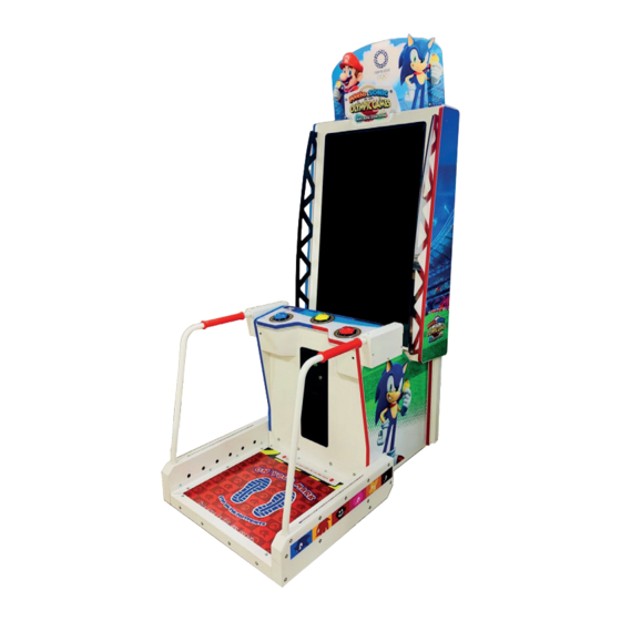
PART DESCRIPTION Billboard Screen Button Grip Handle Floor... -
Page 22: Accessories
ACCESSORIES Confirm that the accessories listed in the table below are present when setting up the product. Accessories marked “Spare” are consumable items but included as spares. PART NAME/NUMBER IMAGE QUANTITY Owner’s Manual (Part #: 420-0038UK) Master Key Security Key Power Lead (Location Dependant) UK (Pt No LM1227) -
Page 23: Assembly And Installation
ASSEMBLY AND INSTALLATION ● Perform assembly work by following the procedure herein stated. Failure to comply with the instructions can cause electric shock and/or serious injury ● Perform assembly as per this Manual. Since this is a complex machine, incorrect assembling can cause an electric shock, machine damage and/or improper functioning as per specified performance ● When assembling, more than one person is required. Depending on the assembly work, there are some cases in which working by one person alone can cause personal injury or parts damage ● Ensure that connectors are properly connected. Improper connections can cause electric shock ● Be careful not to damage the wires. Damaged wires may cause electric shock or short circuit or present a risk of fire ● This work should be carried out by site maintenance personnel or other qualified professionals. Work performed by non-technical personnel can cause a severe accident such as electric shock. Failing to comply with this instruction can cause a severe accident such as electric shock to the player during operation. If no one with proper technological expertise is available, request service from the office indicated in this document or the point of purchase so as to ensure safety ● Provide sufficient space so that assembling can be performed. Performing work in places with narrow space or low ceiling may cause an accident and assembly work to be difficult ● To perform work safely and avoid serious accident such as the cabinet falling down, do not perform work in places where step-like grade differences, a ditch, or slope exist ● Do not leave power cords or Ground Wires exposed in areas of heavy foot traffic. Doing so may cause them to become damaged, possibly resulting in electric shock and/or short circuits. When laying wiring across the floor, always use safety covers to protect the wires (wiring diameter: power cable - approx. φ 8) ● Have a flashlight or another supplementary lighting unit available while working. -
Page 24: Installing The Floor
● Handle molded parts with care. Excessive weight or pressure may cause them to break and the broken pieces may cause injury ● To perform the operation safely and accurately you must use a safe, steady footstool or stepladder. Working without this may lead to a fall and possible injury ● When attaching or removing doors or lids, be careful that your hand or finger does not get caught in anything ● Be very careful when handling the LED display screen. The screen can be damaged easily and cannot be repaired once damaged. Such damage can only be repaired by completely replacing the screen. ● Be careful not to damage parts surfaces. In some cases, if such surfaces are damaged, the part must be replaced; it cannot be reinforced or repaired. 6-1 INSTALLING THE FLOOR Remove the (11) highlighted fixings and remove Plate Floor Sensor Outer RH (MSJ-3023UK) Perform the same procedure on the Plate Floor Sensor Outer LH (MSJ-3022UK) - Page 25 Move the Assy Floor into the position shown. Take care not to trap any wiring during this movement Secure the wiring harnessing through the vacancy in the side of the Cabinet and connect to the adjacent wire harness on the inside of the Cabinet Wire Harness Secure Here Secure the (2) highlighted fixings to secure the Assy Floor Base to the Monitor Cabinet (fixings will be populated within the Cabinet. They must be removed and then reapplied)
-
Page 26: Installing The Pipes
Complete the same procedure on the left hand side Do not yet reapply the Plate Floor Sensor Outer RH/LH as access will be needed in Section 6-3 6-2 INSTALLING THE PIPES Move the Assy Pipe RH into the position shown Secure the (2) highlighted fixings at the base of the pipe. The Paint Piercing Washer must be in contact with the pipes first. All fixings used are located inside the Cash Box... - Page 27 Remove the (5) highlighted fixings and remove the Cover Pipe Upper R (MSJ-3043UK) (fixings will be populated within the Cabinet. They must be removed and then reapplied) Apply and secure the (2) M4x25 fixings into each of the Plate Disc Pipe Mounts (MSJ-3034UK) (fixings will be populated within the Cabinet. They must be removed and then reapplied) Plate Disc Pipe Mount Complete the same procedure for the Assy Pipe LH (MSJ-3030UK) Reapply the Cover Upper Pipe L and R Reapply the Plate Floor Sensor Outer RH and LH...
-
Page 28: Securing The Floor
6-3 SECURING THE FLOOR Apply the Brkt Floor Joint Cabi (MSJ-3056UK) and secure the (8) highlighted fixings (fixings will be populated within the Cabinet. They must be removed and then reapplied) 6-4 INSTALLING THE BILLBOARD AND POP PANEL ● Do not perform installation of the Billboard and/or Pop Panel without the use of a stepladder ● Do not perform installation of the Billboard and/or Pop Panel with less than 2 people The Pop Panel will need to be installed first. Fix the Brkt Pop Title (MSJ-0002UK) into the position shown by securing the (2) highlighted fixings... - Page 29 Place the Billboard Pop Title (MSJ-0001UK) into the position shown and secure with the (2) highlighted fixings (secure from the front of the Billboard) Place the Brkt Billboard R (MSJ-0006UK) and Brkt Billboard L (MSJ-0005UK) into the positions shown and secure using the (4) highlighted fixings Place the Billboard Pop Back (MSJ-0003UK) into position and secure using the (4) highlighted fixings (secure from the front of the Billboard)
-
Page 30: Components That Change State Upon Power
6-5 COMPONENTS THAT CHANGE STATE UPON POWERING UP Game initialises Screen LEDs illuminate Sound from Speakers Floor LEDs illuminate... -
Page 31: Fixation To Site
6-6 FIXATION TO INSTALLATION SITE Make sure that all the adjusters contact the floor. Otherwise the cabinet could move, causing an accident. The product comes with castors attached at 4 locations and adjusters at 8 locations. When the installation site has been determined, have the adjusters come in direct contact with the floor. Establish a gap of about 5 mm between the floor and the casters and adjust the unit so that it will remain level. ADJUSTER (8) CASTOR (4) Move the product to the installation site. If the product is to be installed near a wall, secure enough passage- way space for players to access the seat. You must also secure a 15cm space between the back wall and the back of the cabinet for ventilation. Bring the adjusters into direct contact with the floor. Use a wrench to align the height of the adjusters until the cabinet is perfectly level. After setting, turn adjuster nuts upwards to tighten them and secure adjuster heights. -
Page 32: Connection Of Power Cables
ADJUSTER Tighten nut upwards. About 5 mm ADJUSTER CASTOR 6-7 CONNECTION OF POWER AND GROUND CABLES (Only applies where an integral earth is not present in the mains/power lead.) ● Use the power supply equipped with an earth leakage breaker. Use of power supply without such a breaker could result in fire if there is a current leakage ● Have available a securely grounded indoor ground terminal. Without proper grounding, customers could be electrocuted and product operations might not always be stable ● Do not expose the power cord or ground wire. If these are exposed, customers could stumble over them, for instance, and easily damage them. Additionally, if these lines are damaged, there could be a risk of electrical shock or short circuit. Set these lines at locations where they will not interfere with customer traffic, or attach covers to them ● After laying out the power cord on the floor, be sure to always protect it. If the... - Page 33 Confirm that the main switch is at OFF. INLET FUSE / CIRCUIT PROTECTOR Main switch OFF MAIN SWITCH POWER CORD To Outlet Fully insert the power cord connector on the side opposite the power plug into the AC unit inlet. Fully insert the power cord plug into the outlet. The power cord is laid out indoors. Protect the power cord by attaching wire cover to it. If ground will be established with a ground wire made available separately, lay out the ground wire indoors and have it protected.
-
Page 34: Linking Cabinets
6-8 LINKING CABINETS When operating as a 2 player set up, you must connect each cabinet together by using the supplied LAN cable. Each Cabinet is then assigned a unique ID. Position the Cabinets within a suitable proximity to one another Take the LAN cable and connect it to connection point of Cab 1. Connect the opposite end to the con- nection point of Cab 2 Cab 2 Cab 1 Player 2 Player 1 ID 2 ID 1 LAN Cable DIP Switch settings must be changed in order to apply Cab IDs correctly. Enter the Game Test Mode, select the “System Information” Option, then the following “System Configuration” option. Consult the following table for DIP Switch settings depending on the number of Cabs:... - Page 35 All cabs must be power cycled after DIP Switch settings have been changed. In order to set up a 3 or 4 Player Cabinet configuration, Cabinets must be connected via a network hub and addition- al LAN cables (sold separately). Consult the diagram below on how to set up a 4 player configuration: Cab 2 Cab 1 Cab 4 Cab 3 Player 2 Player 1 Player 4 Player 3 ID 2 ID 1 ID 4 ID 3...
-
Page 36: Confirmation Of Installation
6-9 CONFIRMATION OF INSTALLATION Use test mode to confirm that assembly is proper, connecting boards, and input/output devices are normal. See Sec- tion 9 “Test and Service Data” for more information on each individual test. Perform the following tests in test mode: Unlock and open the Coin Door to access the SW Unit. Use the Test Button to enter the Test and Service Menu SW Unit Enter the section “Input Test”. Ensure that all Buttons and Foot Sensors are working correctly Enter the section “Output Test”. Ensure that all LEDs are functioning correctly... -
Page 37: Precautions Regarding Moving
PRECAUTIONS WHEN MOVING THE MACHINE • As used in these instructions, the term “moving” refers to moving of the product within the same building, store or facility. These instructions do not cover moving between different buildings, areas, stores or facilities, since diverse factors are involved, not only packaging but also loading onto transport vehicles, and securing the product in place during transport. - Page 38 • When inserting or removing a connector, always hold it by its main part. If you hold it by anything else while doing so, the connections between wire and connector terminal fixtures could be damaged; and there could be a short circuit or fire.
- Page 39 • Do not push plastic parts or any part associated with the moving mechanism. Do not lift or support the product by any plastic part. Parts can be damaged, and fragments can cause injury. • Do not push on or hold onto the LCD to move the unit. Doing so could break the parts and lead to people getting injured.
-
Page 40: Game Description
GAME DESCRIPTION 8-1 GAME OUTLINE After the coins are inserted, available Credits will display at the bottom of the screen. After required coins are inserted, the text will change from “PLEASE INSERT COINS” into “PRESS START BUTTON”. The start button on the Cabinet will then be flashing. Coin system can accumulate up to 24 Credits. - Page 41 Event Instructions Before every event, the Player will be shown a brief overview of the controls and the win conditions of the event, e.g. 100m Sprint = finish the race as fast as possible Once the Player has been told the controls and goal of the event, the event will begin.
- Page 42 Results After each event, the Player will be shown their results. Ranking and Name Entry After all events have been completed, the Player will be shown how their score ranks on the leaderboard. If they have received a high enough score, they will be able to input their initials at the Name Entry screen.
-
Page 43: Test And Service Data
Game Board itself. Do not perform changes in the System Test Mode. Only qualified personnel or SEGA technicians should operate settings in the System Test Mode. Perform tests and data checks periodically by manipulating the TEST Button and SERVICE Button in the cabinet. -
Page 44: Sw Unit And Coin Meter
9-1 SWITCH UNIT AND COIN METER The Switch Unit and Counters are housed within the Coin Tower. To access these controls you will need to open the Coin Door. The Switches and Counters can be found directly on the rear face of the Tower. -
Page 45: Game Test Mode
9-2 GAME TEST MODE This is the main Test Mode menu. Here you can access a number of different sub menus to test different aspects of the Cabinet to ensure they are all working correctly. GAME TEST MENU BOOKKEEPING INPUT TEST OUTPUT TEST GAME &... -
Page 46: Bookkeeping
9-3 BOOKKEEPING This menu shows information about Credits received. COIN1 COIN2 TOTAL COINS COIN CREDITS SERVICE CREDITS TOTAL CREDITS Bookkeeping 1/2 COIN1 Number of Coins entered for Player 1 COIN2 Numberof Coins entered for Player 2 TOTAL COINS Total number of Coins entered COIN CREDITS Total number of Coin credits SERVICE CREDITS... - Page 47 This menu shows information like number of Games played and total time.. NUMBER OF GAMES NUMBER OF FIRST PLAY NUMBER OF CONTINUE TOTAL PLAY CREDITS FIRST PLAY CREDITS CONTINUED CREDITS TOTAL TIME PLAY TIME AVERAGE PLAY TIME LONGEST PLAY TIME SHORTEST PLAY TIME Bookkeeping 2/2 NUMBER OF GAMES...
-
Page 48: Input Test
9-4 INPUT TEST This menu is used to test all Input devices are functioning correctly. TEST SERVICE LEFT BUTTON CENTER BUTTON RIGHT BUTTON LEFT RIGHT FOOT OFF OFF JUMP1 JUMP2 JUMP3 JUMP4 JUMP5 JUMP6 TEST Tests function of Test Button SERVICE Tests function of Service Button LEFT BUTTON... -
Page 49: Output Test
9-5 OUTPUT TEST This menu is used to test all Output devices are functioning correctly. MONITOR LED LEFT MONITOR LED RIGHT LED BUTTON LEFT LED BUTTON CENTER LED BUTTON RIGHT CONTROL PANEL LED LEFT CONTROL PANEL LED LEFT LED FLOOR LEFT LED FLOOR RIGHT MONITOR LED LEFT Tests lighting of left Monitor LED (Red, Green, Blue, White) -
Page 50: Game And Coin Assignments
9-6 GAME AND COIN ASSIGNMENTS This menu is used to test Game specific settings like difficulty and the price of play. ADVERTISE SOUND VOLUME MODE SETTING NUMBER OF EVENTS MISSIONS DIFFICULTY LEVEL BONUS GAME REQUIREMENTS GAME PLAY SETTING EVENT TIME ASSIST SELECT CHARACTER SELECT EVENT SELECT... -
Page 51: Monitor
VIDEO DISPLAY The LCD display screen is adjusted prior to leaving the factory. Avoid any unnecessary adjustment ● If the adjustment method in this Manual does not resolve the problem, contact the customer service number in this Manual or your supplier ● Do not stick tape, stickers, or anything else onto the screen. Any kind of adhesive may damage the surface of the screen 10-1 GENERAL DESCRIPTION This specification applies to the 55 inch Color TFT-LCD Module P650HVN02.0. This LCD module has a TFT active matrix type liquid crystal panel 1920x1080 pixels, and diagonal size of 54.6 inch. -
Page 52: Cleaning The Screen
10-2 CLEANING THE SCREEN ● Since the LCD display screen is susceptible to damage, pay careful attention to its handling. When cleaning, refrain from using water or volatile chemicals ● Do not climb onto the control panel. This could lead to injuries, such as bumping your head ● When reaching across the control panel to clean the screen there is a risk of hurting your shoulder or arm. Use a mop with a non-feathery, soft, dry cloth mop head and wipe the surface of the screen When the screen surface becomes dirty, clean it by using a soft cloth such as gauze. When water and volatile chemicals such as benzene, thinner, etc., spill on the screen surface, it may be subject to damage. -
Page 53: Controller Unit
CONTROLLER UNIT ● When working with the product, be sure to turn the power off. Working with the power on may cause an electric shock or short circuit ● Be careful not to damage the wires. Damaged wires may cause an electric shock, short circuit or present a risk of fire ● Do not touch any parts that are not specified in these directions. Touching unspecified locations may lead to electric shock or cause short circuits ● This work should be performed by site maintenance personnel or other skilled professionals. Work performed by non-technical personnel can cause a severe accident such as an electric shock ● Exercise due caution in performing soldering procedures. If soldering iron is handled carelessly, there could be fires or burns ● Proceed very carefully when heating the thermal contraction tube. Careless operations can result in fires or burns ● When fastening plastic parts, be careful not to tighten screws and nuts exces- sively. Otherwise parts may be damaged, resulting in injuries from fragments, etc ● Be careful not to get hand or finger caught when removing or attaching the parts ● Disconnection and connection of connectors will be performed within the nar- row cabinet space. Take due care not to scratch or otherwise injure yourself ● Take care when carrying the removed Control Units. Such heavy lifting carries a risk of injury to back or shoulders ● After the volume has been replaced, be sure to set the volume value on the test mode calibration screen and the input test screen and check variations in the volume value ● After adjusting or replacing a microswitch, always check ON/OFF of the switch on the input test screen of the test mode ● Handle parts inside the Control Unit very carefully. Be especially careful to avoid damage, deformation or loss of these parts. If any one of these parts is lost or defective, it can result in damages and/or faulty operations If the operability of the Control Unit is unsatisfactory, or if settings on the test mode calibration... -
Page 54: Removing The Buttons
11-1 REMOVING THE BUTTONS Turn OFF the power to the machine Remove the (4) fixings on each of the (2) Brkt Front Closing (MSJ-1009UK) This will grant access to the Blue and Red Buttons. Here you can remove the connections to the Buttons... - Page 55 To access the Yellow Button, unlock and open the Coin Door The Yellow Button connection will be located at the top. Remove the connection The Buttons can now be lifted and removed out of the Control Panel...
-
Page 56: Coin Handling
COIN HANDLING Handling the Coin Jam If the coin is not rejected when the REJECT button is pressed, open the Coin Chute Door and open the Selector Gate. After removing the jammed coin, put a normal coin in and check to see that the selector correctly functions. - Page 57 CLEANING THE COIN SELECTOR (MECHANICAL) Remove and clean smears by using a soft cloth dipped in water or diluted chemical detergent and then squeezed dry Remove the CRADLE. When removing the retaining ring (E ring) be very careful so as not to bend the rotary shaft Remove stain from the rotary shaft and shaft CRADLE...
- Page 58 CLEANING THE COIN SELECTOR (SR3 / NRI) Remove and clean smears by using a damp soft cloth dipped in water. DO NOT use any diluted chemical detergent or cleansing agent as this will impair the workings of the GATE component Open the reject gate to gain access to the rundown path RUNWAY...
-
Page 59: Fault Finding
12-2 FAULT FINDING The following information is presented for customers’ guidance in rectifying a fault but does not cover all possible causes. All acceptors with electronic faults should be returned to an approved service centre for repair. SYMPTOM INVESTIGATE POSSIBLE CAUSE Poor Contact Connector Loose Wire... -
Page 60: Adjusting The Price Of Play
12-3 ADJUSTING THE PRICE OF PLAY (EXCEL) ● The price of play is determined by the configuration of switches located on either the EXCEL or VTS board. The type of board used is determined by product location. Switch settings for both types of board remain the same This product comes equipped with a Crane NRI Coin Acceptor. To adjust the price of play ALL CREDIT SETTINGS are adjusted via the EXCEL CREDIT BOARD. -
Page 61: Lamps And Lighting
LAMPS AND LIGHTING • When working with the product, be sure to turn the power off. Working with the power on may cause an electric shock or short circuit. • Pay full attention to lamps when performing work as their high temperatures can cause burns and/or skin damage •... -
Page 62: Led Layout
13-2 LED LAYOUT Diagram Number Diagram Number Part # Lighting LED 10MM WHITE CLUSTER 12V EP1509 161-212103-9 LED 10MM RED CLUSTER 12V EP1510 161-212103-2 LED 10MM BLUE CLUSTER 12V EP1511 161-212103-6 LED BAR RGB 27PCS 40P 390-7185-91 W12MM 5V... -
Page 63: Periodic Inspection
PERIODIC INSPECTION The items listed below require periodic check and maintenance to retain the performance of this machine and to ensure safe business operation. When handling the controller, the player will be in direct contact with it. In order to always allow the player to enjoy the game, be sure to clean it regularly. - Page 64 Cleaning the Cabinet Surfaces When the cabinet surfaces are badly soiled, remove stains with a soft cloth dipped in water or diluted with a chemical detergent and squeezed dry. To avoid damaging surface finish, do not use such solvents as thinner, benzine, etc.
- Page 65 PERIODIC INSPECTION TABLE PERIOD ITEMS DESCRIPTION As appropriate CABINET SURFACE Cleaning ELECTRONIC Inspection COMPONENTS JUMP SENSORS Cleaning MONITOR Cleaning Daily CABINET Confirm adjusters contact floor Floor Joint Bkt - Loose Screws CASH BOX Empty Coins Weekly BUTTONS Check Input in Test FOOT SENSORS Check Input/Output in Test JUMP SENSORS...
-
Page 66: Troubleshooting
TROUBLESHOOTING 15-1 TROUBLESHOOTING (WHEN NO ERROR MESSAGE IS SHOWN) • This work should be performed by site maintenance personnel or other skilled professionals. Work performed by non-technical personnel can cause a severe accident such as an electric shock. If there are no site maintenance personnel or other skilled professionals available, turn off the power immediately and contact the office given in this manual or from point of purchase •... - Page 67 If a problem occurs, first check to make sure that the wiring connectors are properly connected. 15 TABLE 01 PROBLEM POTENTIAL CAUSE COUNTERMEASURES Firmly insert the plug into the The power is not ON outlet Make sure that the power supply/ Incorrect power source/voltage voltage are correct When the Main...
-
Page 68: Game Board
GAME BOARD ● When working with the product, be sure to turn the power off. Working with the power on may cause an electric shock or short circuit. ● Be careful not to damage the wires. Damaged wires may cause electric shock, short circuit or present a fire risk. ● Do not expose the game board, etc. without good reason. Failure to observe this can cause electric shock hazard or malfunctioning. ● Do not use this product with connectors other than those that were connected and used with the game board at the time of shipping. Do not carelessly connect wires to connectors that were not used at the time of shipping as this may cause overheating, smoke, or fire damage. ● When returning the game board after making repairs or replacements, make sure that there are no errors in the connection of connectors. Erroneous connections can lead to electrical shock, short circuits or fires. ● When connecting a connector, check the direction carefully. Connectors must be connected in only one direction. If indiscriminate loads are applied in making connections, the connector or its terminal fixtures could be damaged, resulting in electrical shock, short circuits, or fires. ● In this product, setting changes are made during the test mode. The game board need not be operated. Use the game board, etc. as is with the same setting made at the time of shipment so as not to cause electric shock and malfunctioning. ● Static electricity from your body may damage some electronics devices on the IC board. Before handling the IC board, touch a grounded metallic surface so that the static electricity can be discharged. ● When a game board is to be replaced, put the old game board with anomaly into a special box for replacing the game board. If a special box is not available or if it has been damaged, arrange to have the Game Board packed in suitable packaging. ● For replacement or repair, pack the game board and send it without disassembling it. Order for servicing may not be accepted if any part of the game board has been removed. If any part is removed, a service fee will be charged even if the warranty period has not yet expired. -
Page 69: Removing The Game Board
16-1 HOW TO REMOVE GAME BOARD The game board is located behind the Door Back Lower (MSJ-1002-BUK) in the bottom right hand corner. Turn off the power Remove the (2) highlighted door release fixings from the Door Back Lower Unlock with the master key and remove the door. The ALLS UX Game Bd is located on the right hand side GAME BD... - Page 70 Disconnect all of the connectors connected to the Game Bd Unscrew the (2) screws on each of the (2) Bracket GameBD Mount (MSJ-4002UK) which secure the Game Board in place Lift and remove the Game board from the cabinet. The Game Bd is HEAVY so take care not to clash with other components when removing as this could cause component damage.
-
Page 71: Composition Of The Game Board
16-2 COMPOSITION OF THE GAME BOARD ● With the key chip inserted into it, this board serves as a special-purpose game board for the product... -
Page 72: Error Messages
16-3 ERROR MESSAGES ● If an error is displayed, have the site maintenance personnel or other qualified individuals resolve it. If someone with specialised or technical knowledge attempts to rectify the problem, electric shock, short circuits or fire may occur ● If there are no site maintenance personnel or qualified individuals available, turn off the power and contact the office listed in this manual or point-of-pur- chase ● If a problem not described in this manual or other related manuals occurs, or the resolution to a problem described in this manual is not effective, do not make further attempts to resolve the problem yourself. Immediately turn off the power and contact the office listed in this manual or the point-of-purchase ● Static electricity from your body may damage some electronic devices on the ALLS UX. Before handling, touch a grounded metallic surface so that the static electricity can be discharged ● Do not repeatedly turn the power on/off in a short period of time. Doing so may result in a breakdown or parts damage ● If an error number or message occurs that is not listed below, cease using the product immediately and contact the office listed in this manual or the point-of- purchase ● The error display may be different depending on the game program... - Page 73 ERROR MESSAGES 0001 Display Error 0001 Keychip Not Found Cause There is no key chip, or the key chip is not connected correctly. Measures 0002 Display Error 0002 Keychip Not Available Cause The key chip is not supported. Measures Check the key chip and installation media (such as the DVD) combination. 0004 Display Error 0004...
- Page 74 ERROR MESSAGES 0042 Display Error 0042 Game Program Not Found on Install Media Cause Some part of the game program is missing. Measures Check how the game program was installed. 0049 Display Error 0049 (0052) 0052 Install Media Access Failed Cause Failed to access the installation media.
- Page 75 ERROR MESSAGES 0084 Display Error 0084 Storage Device Malfunctioning Cause The main storage (SSD) may be broken. Measures Turn the power off and restart the ALLS UX. 0085 Display Error 0085 Invalid Storage Format Cause The main storage (SSD) format is wrong. Measures product.
- Page 76 ERROR MESSAGES 0906 Display Error 0906 Sound Function Not found Cause The ALLS UX sound function cannot be recognized. Measures product. 0907 Display Error 0907 Not Enough System Memory Cause The game program does not have enough memory. Measures product. 0909 Display Error 0909...
- Page 77 ERROR MESSAGES 0919 Display Error 0919 DVD Drive Remain Error Cause The installation DVD drive (DVD installation media) remains connected. Measures Take off the DVD drive. 0920 Display Error 0920 Wrong Coin Assignments Cause The game program does not support the current coin assignments. Measures 0949 Display...
- Page 78 ERROR MESSAGES 8004 Display Error 8004 Network setting error (Dup.IP) Cause The SYSTEM TEST MODE NETWORK SETTING is incorrect. Measures 8005 Display Error 8005 Network type error (WAN) Cause The line type of the connected ALL.Net router is incorrect. Measures Check the line type of the connected ALL.Net router.
- Page 79 ERROR MESSAGES 8106 Display Error 8106 ALL.Net System Caution Cause A connection could not be established with ALL.Net. Measures and the connection between the ALL.Net router and the network cable, and then follow the startup procedures to restart the ALLS UX. If the error persists, check the maintenance information.
- Page 80 ERROR MESSAGES 8301 Display Error 8301 Cause The connection with the devices that make up this game could not be Measures Check the network connection and follow the startup procedures to restart the ALLS UX. 8302 Display Error 8302 Maintenance time (GAME) Cause Currently the server is undergoing maintenance.
-
Page 81: System Test Mode
16-4 SYSTEM TEST MODE ● Various settings start saving by selecting EXIT on each test screen and pressing the TEST button. Saving is complete when it displays previous screen automati- cally. Note that the settings will be lost if the power is turned off before saving is complete ● The Test screen display may change depending on the OS version ● The System Test Mode controls various functions on the ALLS UX Game Board. Only qualified technicians or SEGA personnel should make changes or adjust settings in the System Test Mode SYSTEM INFORMATION Displays information on the keychip, board version and the error log STORAGE INFORMATION Displays information on the installed Game USB I/O BD TEST... - Page 82 SYSTEM INFORMATION This section shows information about the ALLS UX Board. Page 1 Page 2 STORAGE INFORMATION ● Do not inadvertently execute “Uninstall”. Using this command will require the game program to be reinstalled This section shows information about the stored game program.
- Page 83 USB I/O BOARD TEST This section shows information about the connected I/O Board(s) For the I/O Board Input Test, consult the ALLS UX Game Board Manual...
- Page 84 SYSTEM TEST MODE SYSTEM TEST MODE MONITOR TEST This section checks the output of the monitor. Use MONITOR TEST to check the output of the monitor. Use MONITOR TEST to check the output of the monitor. MONITOR TEST 1/2 MONITOR TEST 1/2 PRESS TEST BUTTON TO NEXT PRESS TEST BUTTON TO NEXT MONITOR TEST 1/2 screen...
- Page 85 COIN ASSIGNMENTS ● Do not inadvertently change the Coin to Credit ratio in the System Test Mode. Use the Game and Coin Assignments in the Game Test Mode This section can amend coin to credit ratio (changes on installed game) For the Coin to Credit table and more detail on the Coin Assignments, consult the ALLS UX Game Board Manual...
- Page 86 CLOCK SETTING This section changes the internal clock. To set the time, use the SERVICE button to move through the Year - Month - Day - Hours - Minutes - Seconds - SET - CANCEL options. Use TEST to increase the value of the selected item. Use SET to confirm the newly selected time.
-
Page 87: Design Related Parts
DESIGN RELATED PARTS For the warning display stickers, refer to Section 1. -
Page 88: Parts List
PARTS LIST MARIO AND SONIC TOKYO 2020 STRUCTURE FLOW MARIO & SONIC AT TOKYO OLYMPICS BOM STRUCTURE MSJ-0000UK TOP ASSY MARIO & SONIC AT TOKYO OLYMPICS **** MSJ-1000UK MSJ-1080UK ASSY MAIN CABI ASSY AC UNIT MSJ-0320UK ASSY SW UNIT MSJ-2100UK ASSY CTRL PANEL MSJ-4000UK ASSY GAMEBOARD... - Page 89 1 TOP ASSY MSJ (MSJ-0000UK) ITEM NO PART # DESCRIPTION MSJ-1000UK ASSY MAIN CABI 421-7988-91UK STICKER SERIAL NUMBER UK 440-WS0010UK WARN LABEL - HI VOLTAGE LB1046 LABEL TESTED FOR ELEC. SAFETY LB1130 LABEL WEEE WHEELIE BIN 440-CS0186-01UK STICKER C EPILEPSY 40 440-CS0010UK LABEL CAUTION GENERIC 440-DS0010UK...
- Page 90 2 ASSY SW UNIT (MSJ-0320UK) 201 202 ITEM NO PART # DESCRIPTION ***1 SSR-0321UK SW BRKT DOUBLE METER ***102 280-L00706-PM STANDOFF 6.4L 4MM LCBS-5-4-01 ***103 EP1380-01 CREDIT BOARD EXCEL ***104 220-5643UK COIN METER SMALL 12V ***105 OS1247 ALUMINIUM STICKY CLIP ASK-3 475-198 ***106 421-12043-01 STICKER SW PLATE CE...
- Page 91 3 ASSY MAIN CAB (MSJ-1000UK) 102 206 210 211 212 213 214...
- Page 92 3 ASSY MAIN CAB (MSJ-1000UK)
- Page 93 3 ASSY MAIN CAB (MSJ-1000UK)
- Page 94 3 ASSY MAIN CAB (MSJ-1000UK) ITEM NO PART # DESCRIPTION MSJ-1002UK ASSY MAIN CABI MSJ-1080UK ASSY AC UNIT MSJ-0320UK ASSY SW UNIT MSJ-2100UK ASSY CTRL PANEL SND-1340UK ASSY FAN MSJ-4000UK ASSY GAME BOARD MSJ-4100UK ASSY ELEC MSJ-4500UK ASSY LED MONITOR ELEC **10 MSJ-1003UK STRUT TOP CABI SUPPORT...
- Page 95 3 ASSY MAIN CAB (MSJ-1000UK) ITEM NO PART # DESCRIPTION **301 MSJ-60007UK WH MONITOR PWR **302 MSJ-60008UK WH COIN HANDLING LINK **303 MSJ-60010UK WH PLAYER BUTTONS **304 MSJ-60011UK WH SPEAKERS **305 MSJ-60012UK WH FAN AND BILLBOARD **306 MSJ-60013UK WH CONTROL PANEL LIGHTING **307 MSJ-60014UK WH FLOOR LINK...
- Page 96 4 ASSY AC UNIT (MSJ-1080UK) ITEM NO PART # DESCRIPTION ***1 DA-1081UK PLATE AC ***2 TFF-0402UK CONN COVER ***3 LB1096 STICKER PROTECTIVE EARTH ***4 LB1131 LABEL ON / OFF ***101 EP1302 EUROSOCKET FUSED 10A 250VAC ***102 514-5078-3150 FUSE 3.15 X 20 CERAMIC SB 3150mA ***103 SW1109 SWITCH ROCKER 250V AC...
- Page 97 5 ASSY CONTROL PANEL (MSJ-2100UK) ITEM NO PART # DESCRIPTION ***1 MSJ-2101UK BOARD CTRL PANEL ***26 MSJ-2109UK COVER CTRL PANEL ***101 509-6003-BUK BTN LRG RND BLU 75-4002-12187 ***102 509-6003-YUK BTN LRG RND YEL 75-4002-15187 ***103 509-6003-RUK BTN LRG RND RED 75-4002-10187 ***104 EP1509 LED 10MM WHITE CLUSTER 12V 161-212103-9...
- Page 98 6 ASSY FLOOR & BASE (MSJ-3000UK) ITEM NO PART # DESCRIPTION ***1 MSJ-3010UK ASSY LH PIPE BASE ***2 MSJ-3020UK ASSY RH PIPE BASE ***3 MSJ-3050UK ASSY FLOOR ***201 029-B00840 M8X40 SKT BH PAS ***202 060-S00800 M8 WSHR SPR PAS ***203 068-852216 M8 WSHR 22OD FLT PAS ***204...
- Page 99 7 ASSY LH PIPE BASE (MSJ-3010UK) ITEM NO PART # DESCRIPTION ****1 MSJ-3011UK FRAME LH PIPE BASE ****2 MSJ-3012UK BRKT FOOT SENSOR ****3 MSJ-3013UK PLATE FLOOR SENSOR OUTER LH ****4 MSJ-3014UK LIGHT GUIDE UPPER ****7 MSJ-3019UK COVER FLOOR SENSOR INNER ****10 MSJ-3015UK STICKER PIPE BASE L...
- Page 100 8 ASSY RH PIPE BASE (MSJ-3020UK) ITEM NO PART # DESCRIPTION ****1 MSJ-3011UK FRAME RH PIPE BASE ****2 MSJ-3012UK BRKT FOOT SENSOR ****3 MSJ-3013UK PLATE FLOOR SENSOR OUTER RH ****4 MSJ-3014UK LIGHT GUIDE UPPER ****7 MSJ-3019UK COVER FLOOR SENSOR INNER ****10 MSJ-3015UK STICKER PIPE BASE R...
- Page 101 9 ASSY LH PIPE (MSJ-3030UK) 207 209 ITEM NO PART # DESCRIPTION ***1 MSJ-3031UK PIPE ***2 MSJ-3032UK BRKT MOUNT PIPE UPPER L ***3 MSJ-3033UK COVER PIPE UPPER L ***8 MSR-3102 SIDE GRIP UPPER ***9 MSR-3103 SIDE GRIP LOWER ***201 029-B00850 M8X50 SKT BH PAS ***202 068-852216...
- Page 102 10 ASSY RH PIPE (MSJ-3040UK) 207 209 ITEM NO PART # DESCRIPTION ***1 MSJ-3031UK PIPE ***2 MSJ-3032UK BRKT MOUNT PIPE UPPER R ***3 MSJ-3033UK COVER PIPE UPPER R ***8 MSR-3102 SIDE GRIP UPPER ***9 MSR-3103 SIDE GRIP LOWER ***201 029-B00850 M8X50 SKT BH PAS ***202 068-852216...
- Page 103 11 ASSY FLOOR (MSJ-3050UK) 210 211 ITEM NO PART # DESCRIPTION ***1 MSJ-3051UK BASE FLOOR ***2 MSJ-3052UK PANEL FLOOR ***3 MSJ-3053UK BRKT FLOOR FRONT ***4 MSR-3054UK BRKT FLOOR ***5 MSJ-3055UK BRKT FLOOR SIDE ***7 MSR-3057UK SUPPORT UPPER FLOOR CENTRAL ***8 MSJ-3058UK SUPPORT LOWER FLOOR CENTRAL ***10...
- Page 104 12 ASSY LH FOOT SENSOR (MSJ-3060UK) ITEM NO PART # DESCRIPTION *****1 MSJ-3061UK MOUNT LH FOOT SENSOR *****2 MSJ-3062UK PAD FOOT SENSOR UPPER *****3 MSR-3063UK BRKT SENSOR AUX *****4 MSR-3064UK BRKT SHOCK SENSOR *****101 601-13134 SHOCK SENSOR GID-SG11 PR *****102 OS1246 FOAM TAPE 2MMX18MM 1.44 *****201 029-B00416...
- Page 105 13 ASSY RH FOOT SENSOR (MSJ-3070UK) ITEM NO PART # DESCRIPTION *****1 MSJ-3061UK MOUNT RH FOOT SENSOR *****2 MSJ-3062UK PAD FOOT SENSOR UPPER *****3 MSR-3063UK BRKT SENSOR AUX *****4 MSR-3064UK BRKT SHOCK SENSOR *****101 601-13134 SHOCK SENSOR GID-SG11 PR *****102 OS1246 FOAM TAPE 2MMX18MM 1.44 *****201 029-B00416...
- Page 106 14 ASSY GAME BOARD (MSJ-4000UK) 2 201 202 203 ITEM NO PART # DESCRIPTION ***1 MSJ-4001UK BOARD GAMEBOARD MOUNT ***2 MSJ-4002UK BRKT GAMEBD MOUNT ***101 849-1003 ASSY CASE ALLS HX2 ***102 610-0937-018BE KEY CHIP ALLS X MSJ ***103 280-A01264-WX ROUTER TWIST D12 BHKL-450-4-01 ***201 029-B00416 M4X16 SKT BH PAS...
- Page 107 15 ASSY ELEC (MSJ-4100UK) 2 201 202 203 204 103 - DIP Switch 1 = ON ITEM NO PART # DESCRIPTION ***1 MSJ-4101UK BOARD ELEC ***2 DSD-4002UK PLATE PSU POST ***3 CFB-4003-01UK EARTH TERMINAL PLATE ***101 400-065-005 PSU 5VDC 65W MW EPS-65-5 ***102 400-075-012-01 PSU 12VDC 75W MW LPS 75-12...
- Page 108 15 ASSY ELEC (MSJ-4100UK) ITEM NO PART # DESCRIPTION ***301 MSJ-60003UK WH AC DISTRIBUTION IN ***302 MSJ-60004UK WH AC DISTRIBUTION ***303 MSJ-60005UK WH AC DIST TO GAMEBOARD ***304 MSJ-60006UK WH I/O ***305 600-7055-0180UK 3.5MM JACK TO JACK ***306 MSJ-60020UK WH EARTH LINK ***307 600-7142-200UK USB JVS TYPE A-B FEUSB2HAB 2M...
- Page 109 16 ASSY LED MONITOR ELEC (MSJ-4500UK) ITEM NO PART # DESCRIPTION ***1 MSJ-4501UK PANEL LED MONITOR ELEC ***2 440-DS0010UK LABEL DANGER HI VOLT GEN ***101 400-283-51224 PSU 55" LED DPS-283APA-ESS5 ***102 280-A01264-WX ROUTER TWIST D12 BHKL-450-4-01 ***103 280-L00811-OS STANDOFF 7.94OD 3.56ID 11.11L ***201 012-P00320 N4X3/4"...
- Page 110 17 ASSY INST KIT MSJ STD (MSJ-INST-STD)
- Page 111 17 ASSY INST KIT MSJ STD (MSJ-INST-STD) ITEM NO PART # DESCRIPTION MSJ-3000UK ASSY FLOOR & BASE MSJ-3030UK ASSY LH PIPE MSJ-3040UK ASSY RH PIPE MSJ-0001UK BILLBOARD POP TITLE MSJ-0002UK BRKT POP TITLE MSJ-0003UK BILLBOARD POP BACK **10 MSJ-0005UK BRKT BILLBOARD L **11 MSJ-0006UK BRKT BILLBOARD R...
- Page 112 18 ASSY XFMR BOARD (MSJ-4300UK) - US CABINET ONLY 203 205 206 ITEM NO PART # DESCRIPTION ***1 MSJ-4301UK BOARD XFMR ***101 560-1111-01UK XFMR US BLOCK 630VA ***103 280-A01264-WX ROUTER TWIST D12 BHKL-450-4-01 ***203 029-B00616 M6X16 SKT BH PAS ***205 060-S00600 M6 WSHR SPR PAS ***206...
-
Page 113: Colour Code
WIRE COLOR CODE TABLE The DC power wire color for this product is different from previous SEGA titles. Working from the previous wire colors will create a high risk of fire The color codes for the wires used in the diagrams in the following chapter are as follows:... -
Page 114: Schematic Diagrams
SCHEMATIC DIAGRAMS (1 OF 2) - Page 115 (2 of 2)
- Page 116 SPARES AND SERVICE CONTACT INFORMATION -SEGA TOTAL SOLUTIONS- 42 Barwell Business Park Leatherhead Road Chessington Surrey KT9 2NY United Kingdom Contact: +44 (0) 208 391 8060 Option 1 for Spares, Prize, and Sales Option 2 for Technical, Warranty, and Repairs...
Need help?
Do you have a question about the MARIO & SONIC AT THE OLYMPICS GAMES TOKYO 2020 and is the answer not in the manual?
Questions and answers