Table of Contents
Advertisement
Quick Links
420-6831-01
REV 1
SERVICE MANUAL
DELUXE TYPE
Before using this product, read this SERVICE MANUAL carefully to understand the contents stated herein.
After reading this manual, be sure to keep it available nearby the product or somewhere convenient in
order to be able to refer to it whenever necessary.
Manufactured in the UK by
Advertisement
Table of Contents

Related Manuals for Sega Ghost Squad Deluxe


Summary of Contents for Sega Ghost Squad Deluxe
- Page 1 420-6831-01 REV 1 SERVICE MANUAL DELUXE TYPE Before using this product, read this SERVICE MANUAL carefully to understand the contents stated herein. After reading this manual, be sure to keep it available nearby the product or somewhere convenient in order to be able to refer to it whenever necessary. Manufactured in the UK by...
-
Page 2: Table Of Contents
CONTENTS BEFORE USING THIS PRODUCT .......................3 1.1. INSPECTIONS IMMEDIATELY AFTER TRANSPORTING THE PRODUCT TO THE LOCATION .4 NAME OF PARTS ..........................6 2.1. HOW TO USE THE CHIHIRO BOARD CARTON BOX..............7 2.1.1. INSTRUCTIONS .........................7 2.2. HOW TO USE THE CARTON BOX (GD-ROM DRIVE) ..............9 ASSEMBLY AND INSTALLATION ......................10 3.1. - Page 3 8.2.3. ADJUSTING THE ON-SCREEN CONTRAST................88 8.2.4. ADJUSTING THE SCREEN BRIGHTNESS................89 8.2.5. ADJUSTING THE ON-SCREEN DISPLAY POSITION ............90 8.2.6. ADJUSTING THE SCREEN SIZE ....................91 8.2.7. CONVERGENCE ADJUSTMENT (manual colour matching) ..........92 8.2.8. STATIC CONVERGENCE ADJUSTMENT ................93 8.2.9. POINT CONVERGENCE ADJUSTMENT ................94 8.2.10.
-
Page 4: Before Using This Product
Depending on the potential risk, terms such as” WARNING!” “CAUTION” and “IMPORTANT!” are used where an explanation is given that requires special attention. SEGA is not responsible for injury or damage caused by use in a manner contrary to the instructions given in this document. -
Page 5: Inspections Immediately After Transporting The Product To The Location
TO THE LOCATION • Only QUALIFIED SERVICE PERSONNEL should carry out inspection. Normally, at the time of shipment, SEGA products are in a state to allowing usage immediately after transporting to the location. Nevertheless, an irregular situation may arise during transportation preventing this. - Page 6 CONCERNING THE STICKER DISPLAY CONCERNING WARNING STICKERS SEGA product has stickers describing the product SEGA product has warning displays on manufacture number (Serial Number) and stickers, labels or printed instructions electrical specification. If you require service adhered/attached to or incorporated in the assistance you will require the Serial Number.
-
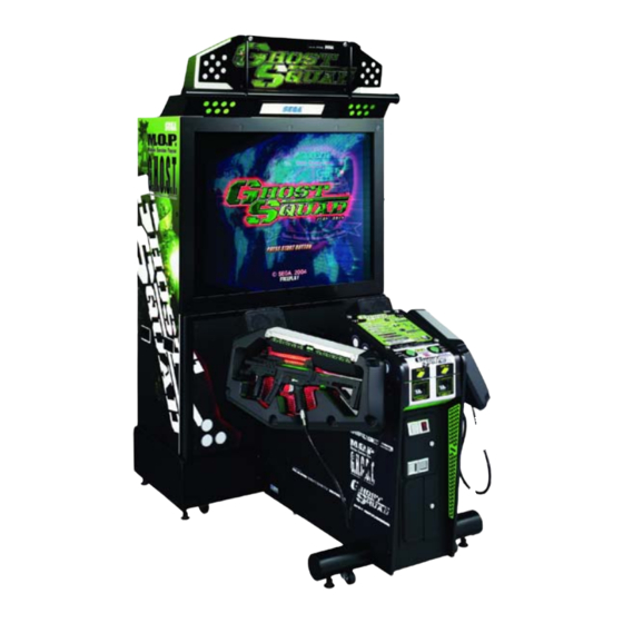
Page 7: Name Of Parts
NAME OF PARTS Width (mm) Length (mm) Height (mm) Weight (kg) 1,140 1,670 PTV BASE 1,200 BILLBOARD 1,170 MAIN CABINET 1,140 1,090 1,010 When Assembled 1,200 1,680 2,230... -
Page 8: How To Use The Chihiro Board Carton Box
2.1. HOW TO USE THE CHIHIRO BOARD CARTON BOX Replacement or repair of the Game Board (Chihiro) for this product should be undertaken at the appropriate repair centre. Be sure to follow the specifications below when requesting repairs/sending the board to the repair centre. Not following the specifications may result in the board not being accepted or in extra charges being made. -
Page 10: How To Use The Carton Box (Gd-Rom Drive)
2.2. HOW TO USE THE CARTON BOX (GD-ROM DRIVE) When you want to order for replacing or repairing service of the GD-ROM drive that is used by the product, pack it in a carton box as instructed below, and then deliver the carton box to a service agent. -
Page 11: Assembly And Installation
ASSEMBLY AND INSTALLATION • Perform assembly work by following the procedure herein stated. Failing to comply with the instructions can cause electric shock hazard. • Perform assembling as per this manual. Since this is a complex machine, erroneous assembling can cause an electric shock, machine damage and or not functioning as per specified performance. - Page 12 When carrying out the assembly work, follow the procedure in the following sequence: STEP 1: ASSEMBLING THE BILLBOARD STEP 2: ASSEMBLING THE CABINET STEP 3: SECURING IN PLACE ADJUSTER TUNING STEP 4: TURNING THE POWER ON STEP 5: ASSEMBLY CHECK The parts contained in the installation kit are required for the assembly work.
-
Page 13: Assembling The Billboard
3.1. ASSEMBLING THE BILLBOARD 1. Undo the 2 truss screws, and remove the pop bracket. 2. Undo the 3 truss screws, and remove the pop holder. 3. Attach the billboard pop by fitting it between the pop bracket and pop holder, and fixing it in place with the 3 truss screws. - Page 14 4. Attach the assembled billboard pop using the 2 truss screws.
-
Page 15: Assembling The Cabinet
3.2. ASSEMBLING THE CABINET 1. Move the PTV to the back of the PTV base. 2. Put the PTV on the PTV base. To do this, you will need at least 4 people to lift the PTV, and another person to hold the PTV base to stop it from moving. Lower the PTV until it touches the supports. - Page 16 4. Have 2 people lift the billboard and place it on the PTV. Lower the billboard so that the two mask bracket uppers that were attached in step 2 fit into the 2 rectangular holes in the billboard base plate, and push the billboard towards the PTV screen. The base plate of the billboard is then fixed into place by fitting into the mask brackets.
- Page 17 7. Connect the internal billboard connector to the connector in the PTV ceiling. 8. Attach the connector lid using the single truss screw. 9. Bring the main cabinet next to the PTV. 10. Connect the wiring between the main cabinet and the PTV. You will need to connect a total of 5 connectors.
- Page 18 12. Tighten the 2 hexagon bolts on each of the left and right brackets of the main cabinet to affix the cabinet. 13. Attach the joint bracket uppers to the left and right sides of the joint between the main cabinet and the PTV using 4 truss screws on each side to secure the joint.
-
Page 19: Securing In Place (Adjuster Tuning)
3.3. SECURING IN PLACE (ADJUSTER TUNING) • Make sure that all of the adjusters are in contact with the floor. If they are not, the cabinet can move and cause an accident. This product has 8 casters (4 for PTV Base, 4 for MAIN CABINET) and 6 Adjusters (4 for PTV Base, 2 for MAIN CABINET). -
Page 20: Turning The Power On
3.4. TURNING THE POWER ON Turn the main switch on the AC unit on to turn the power on. When the power is turned on, the fluorescent lights in the billboard and instruction panel turn on. A few second later, the system startup screen is displayed, then the waiting screen for customers (advertising screen) is displayed. -
Page 21: Assembly Check
3.5. ASSEMBLY CHECK In the TEST MODE, ensure that the assembly has been made correctly and IC BD. is satisfactory (refer to Section 5). In the test mode, perform the following test: 3.5.1. MEMORY TEST When "MEDIA BOARD TEST" is selected from the System Test Mode Menu Screen the Game Board memory is automatically tested. -
Page 22: Test
3.5.2. C.R.T. TEST In the TEST mode menu, selecting C.R.T. TEST allows the screen (on which the projector is tested) to be displayed. Although the projector adjustments have been made at the time of shipment from the factory, make judgment as to whether an adjustment is needed by watching the test mode screen. -
Page 23: Output Test
3.5.3. OUTPUT TEST Select OUTPUT TEST from the menu in the test mode to cause the screen (on which each lamp and wiring connections are tested) to appear. Ensure that lamp light up satisfactorily. 3.5.4. GUN ADJUSTMENT Before starting the operation, play the game by yourself and make sure that the gun readjustment is not needed and that you can play the game without a problem. -
Page 24: Interference Prevention Wiring
3.6. INTERFERENCE PREVENTION WIRING • In order to prevent electric shock and short circuit hazards, be sure to turn power off before performing work. • Be careful not to damage the wires. Damaged wires may cause electric shock or short circuit or present a fire risk. •... - Page 25 3. The interference prevention wire is connected to the sensor board on the lower right side. If multiple units of the same game are installed side by side, make sure that the game units that are connected to the interference prevention wires are arranged so that they alternate with the units that are not connected.
-
Page 26: Precautions When Moving The Machine
3.7. PRECAUTIONS WHEN MOVING THE MACHINE • When moving the machine, be sure to pull out the plug from the power supply. Moving the machine with the plug as is inserted can cause the power cord to be damaged and could result in a fire and or electric shock. •... - Page 27 When transporting the product over areas with steps or steep slopes, always disassemble into each unit before transporting. Do not hold press these hatched parts to move the product.
-
Page 28: Cautions When Transporting The Machine
3.7.1. CAUTIONS WHEN TRANSPORTING THE MACHINE Do not tie machine down using Plastic Parts as an anchor. When using straps or tie downs (rope etc), use caution. Use protective material where tie downs make contact with the machine to avoid damage. To keep machine from shifting during transport, be certain all leg adjusters are in contact with the pallet. -
Page 29: Game Description
GAME DESCRIPTION Use this section to confirm the machine is operating correctly; if the machine doesn’t operate as described there may be a fault. While power is connected, the billboard is continuously lit and demonstration footage and ranking data are displayed on the screen. -
Page 30: Game Contents
4.1. GAME CONTENTS 4.1.1. GAME OUTLINE The player is a member of the special forces unit, "Ghost Squad", out to suppress vicious terrorists. Each mission contains multiple routes, allowing the player to choose how to proceed. Special events occur throughout the game depending on the route chosen, such as securing hostages or providing friendly cover fire. -
Page 31: Characters
4.1.3. CHARACTERS Alpha Unit The Alpha Unit are the main characters in the game and are young hot-shot members of "Ghost Squad", an unofficial unit of the anti-terrorist group, "M.O.P." (Multiple-Operation-Program). Fellow M.O.P. Members The Commander provides radio backup and pertinent advice to the Alpha Unit. Also assisting the Alpha Unit in operations are Bravo Unit and Charlie Unit. -
Page 32: Game Flow And On-Screen Display
4.1.4. GAME FLOW AND ON-SCREEN DISPLAY Card Insertion Screen [Only with the IC Card] The IC Card Insertion Screen is displayed when starting a game. Insert an IC Card into the card slot to read stored data. To play a game without using an IC Card, select the "Start game without card." panel. IC Card updates are also handled on this screen. - Page 33 Customize Screen [Only with the IC Card] On the Customize Screen, weapons and costumes can be changed. With sufficient game progress, name change and screen display type selection also become available. Customize Screen A Item Scroll Buttons Scrolls through costume type indicators. Rapid scrolling is possible by keeping it held down.
- Page 34 Customize Screen [Only without the IC Card] Starting the game without an IC Card will display the following screen and allow weapon and costume selection. Name Entry Screen When starting a game with a new IC Card, the Name Entry Screen is first displayed. A name chosen once can later be changed on the Customize Screen.
- Page 35 Gun Controller Explanation Screen Exiting the Customize Menu plays the demo explaining how to use the gun controller. This explains the shooting stance, and how to use the SHOT SELECTOR and ACTION button. It is possible to skip this explanation with the START button. Gun Controller Explanation Screen Gun Controller Calibration Screen If the CALIBRATION setting in the game Test Mode is turned on, this screen is displayed before starting...
- Page 36 Mission Select Screen On this screen, the player selects which mission to play from 3 available missions. Playing one mission all the way to the end displays this screen once again, allowing the player to select another mission. A mission played once cannot be played again in the same game. Mission Select Screen The Mission Level is displayed on the Mission Select Screen.
- Page 37 In-game Display During game play, information such as life and remaining ammunition is displayed. During game play, information such as life and remaining ammunition is displayed. Life (remaining health): The colour will grow red as it nears zero. GS Meter: Special Points accumulated during the game are shown here.
- Page 38 Mission Results Screen [Only with the IC Card] After either successfully completing a single mission or dying partway, the Mission Result Screen is displayed. Mission information, including the route taken or event results, can be confirmed on this screen. This screen also displays a notification if the Mission Level has increased. •...
-
Page 39: Game Rules And Gameplay
4.1.5. GAME RULES AND GAMEPLAY Life During play, the player's life is displayed at the top part of the screen. Life is diminished by enemy attack or accidental fire on hostages. Once the player's life runs out, play stops. The amount of life to start a game with can be configured in Test Mode settings. Changing life settings will not affect the length of the life gauge. - Page 40 E-Marker When discovered, the terrorists commence fire upon the player. However, not all shots result in injury. An "E-Marker" will be displayed on any enemy whose shots will inflict damage, serving as a warning to the player. When under fire from multiple enemies, first defeating enemies marked with an E-Marker should help the player avoid damage.
- Page 41 The number of selectable tactics will increase along with the Mission Level. Also, a "NEW" label will be displayed on any newly appearing tactics panels. [When no IC Card is being used, the number of Tactics Selection panels will not increase.] Events (Special Operations) Besides normal terrorist suppression, this game includes additional "events", such as bomb removal or securing hostages.
- Page 42 Auxiliary Items Auxiliary items appear in certain situations during the game. There are two types of auxiliary items, items that are put to use and disappear immediately after picking up, and those that are stocked and continue to be effective over time. The latter type can be used only one at a time.
- Page 43 Costumes This game has 14 different costumes. Initially only 2 are available ("GHOST SQUAD" and "JUNGLE"), but that number increases with further play. The chosen costume can be viewed during in-game cut scenes. Costumes have no direct effect on damage, score, or other game content. [When no IC Card is being used, costumes are chosen from the 4 types shown below.] Weapons As the player's level and rank go up, new weapons become available.
- Page 44 Mid-game Entry It is possible for an additional player to join later, even if a player is in the middle of play. If the necessary number of credits has been inserted, a message (as shown below) is displayed on the bottom part of the screen.
-
Page 45: Ic Cards [Only With The Ic Card]
4.1.6. IC CARDS [ONLY WITH THE IC CARD] Number of Uses The number of uses per IC Card is 100. This number includes expenditure for starting or continuing games. An IC Card with 0 remaining uses cannot be used to start a game. However, if the remaining uses reaches 0 during play, it is possible to continue a game. -
Page 46: Explanation Of Test And Data Display
EXPLANATION OF TEST AND DATA DISPLAY By operating the switch unit, periodically perform the tests and data check. When installing the machine initially or collecting cash, or when the machine does not function correctly, perform checking in accordance with the explanations given in this section. The following shows tests and modes that should be utilized as applicable. -
Page 47: System Test Mode
5.1. SYSTEM TEST MODE • Any settings that are changed by users during TEST MODE are saved upon exiting TEST MODE with the EXIT command in the SYSTEM MENU. If the unit is powered off prior to exiting, changes to settings will not take effect. •... -
Page 48: Media Board Test
5.1.2. MEDIA BOARD TEST • Powering off the system during the MEDIA BOARD TEST with a DIMM BOARD will erase the game programme data. It may be necessary to reload the data. • Always wait for the test to complete before attempting to exit. MEDIA BOARD TEST is used to check the memory and IC on the MEDIA BOARD connected to the Chihiro. -
Page 49: System Information
5.1.3. SYSTEM INFORMATION Use SYSTEM INFORMATION to check version and other information for system programmes. Screens may differ depending on the type of MEDIA BOARD connected to the unit. The following is the SYSTEM INFORMATION screen for a unit with a DIMM BOARD. Press the TEST Button to return to the SYSTEM MENU screen. -
Page 50: Jvs Test
5.1.4. JVS TEST JVS TEST is used to verify the specs of the I/O BOARD connected to the Chihiro and to run input tests. I/O BOARD specs are displayed initially. Screens may differ depending on the type of I/O BOARD connected to the unit. 1. - Page 51 INPUT TEST Screen 5. On-screen values change according to the input from switches and the volume. SYSTEM, PLAYER Values change with input from control panel/other switches. COIN Increases with input from the COIN SWITCH. The count is cleared when exiting TEST MODE.
-
Page 52: Sound Test
5.1.5. SOUND TEST Use SOUND TEST to test sound output and to select the stereo/mono/surround setting. 1. Use the SERVICE Button to move the cursor to the desired test item. 2. Press the TEST Button to enter the selected item. OUTPUT TYPE: STEREO, MONO, SURROUND Select the sound output from the I/O PANEL audio output interface setting among STEREO, MONO and SURROUND... -
Page 53: Crt Test
5.1.6. CRT TEST Use the C.R.T. TEST to adjust monitor colours and verify screen size. COLOUR CHECK Screen (1) Monitor COLOUR CHECK screen is displayed initially. Each of the colours (red, green and blue) is darkest at the far left and gets progressively lighter (32 steps) towards the right. -
Page 54: Coin Assignments
5.1.7. COIN ASSIGNMENTS Use COIN ASSIGNMENTS to set the credit rate for each coin inserted. 1. Use the SERVICE Button to move the cursor to the desired test item. 2. Press the TEST Button to change the setting or to open the detailed settings. 3. - Page 55 COIN TO CREDIT RATE Set the CREDIT RATE for each coin inserted. The "1 COIN(S) COUNT AS 1 CREDIT(S)" setting indicates that "Inserting 1 coins equals 1 credits". Set this to "FREE PLAY" to allow game play without credits. When (A) COIN CHUTE TYPE is set to "COMMON", COIN CHUTE #2 settings are restricted to some extent by the settings for COIN CHUTE #1.
-
Page 56: Game Cost Setting
5.1.8. GAME COST SETTING Use this mode to set the number of credits required to start a game. Screens may differ depending on the game. Set the number of credits required to start a game Set the number of credits required to continue a game. -
Page 57: Clock Setting
5.1.9. CLOCK SETTING Use CLOCK SETTING to set the Chihiro internal clock. 1. Use the SERVICE Button to move the cursor to the item to be set. 2. Move the cursor to the desired item and press the TEST Button to increase values. The max value for YEAR is "2099";... -
Page 58: Network Setting (Core)
5.1.10.NETWORK SETTING (CORE) Use the LAN PORT attached to the Main Board, and carry out the settings necessary for network communication. Note: This function is not available with this product. 1. Use the SERVICE Button to move the cursor to the desired test item. (When setting IP ADDRESS, SUBNET MASK, GAME WAY or PRIMARY DNS, use the underline as a guide.) 2. -
Page 59: Network Setting Media
5.1.11.NETWORK SETTING MEDIA Use NETWORK SETTING to establish and test network connections. This is only displayed the following error message screen. This game does not support network communication connections. -
Page 60: Game Test Mode
5.2. GAME TEST MODE • When changing the game configuration, changes will not take effect until the Game Test Mode has been completed. Be sure to exit the Game Test Mode properly after configuration changes. Select ENTER GAME TEST from the System Menu screen to display the Game Test Menu screen as follows. -
Page 61: Input Test
5.2.1. INPUT TEST Select INPUT TEST to display the following screen and check the status of input devices. This test should be used periodically to check that each input device is functioning correctly. The items refer to the following input devices. TRIGGER: The controller's TRIGGER switch. -
Page 62: Output Test
5.2.2. OUTPUT TEST Select OUTPUT TEST to display the following screen and check the status of each lamp. This test should be used periodically to check that the lamps are functioning correctly. Press the SERVICE Button to move the cursor and the TEST Button to select. Displays ON when selected. PLAYER 1 START LAMP: Lights up the 1P START button. -
Page 63: Game Assignments
5.2.3. GAME ASSIGNMENTS Select GAME ASSIGNMENTS to display the current game settings and make changes. Perform the following settings for each item. DIFFICULTY: Choose the difficulty level of the game from EASY, NORMAL and HARD. The product is shipped with the default set at NORMAL. LIFE: Choose the amount of life given for players starting a new game between 1 and 7. -
Page 64: Gun Adjustment
5.2.4. GUN ADJUSTMENT Select GUN ADJUSTMENT to display the following screen. This screen allows you to adjust the gun using the five calibration targets (TOP, LEFT, CENTRE, RIGHT, BOTTOM). Use each target to calibrate as follows. Use the standard gun controller, carefully aim at the correct target and pull the trigger to calibrate the value. Select between the calibration targets with the 1P and 2P START buttons or SERVICE button. - Page 65 BOTTOM x y: Set the BOTTOM value. The number on the left (x) is the horizontal component, and the number on the right (y) is the vertical component. Aim the controller at the BOTTOM target and pull the trigger to set the value. This will not affect horizontal calibration.
-
Page 66: Card Read/Write Test
5.2.5. CARD READ/WRITE TEST Select CARD READ/WRITE TEST to display the following screen with testing options for the reading and writing of IC Cards. Use this screen regularly to test the functionality of the machine. First, insert an IC Card into the slot, then press the SERVICE button to choose the item for testing. When the cursor is on the desired item, press the TEST Button. -
Page 67: Close Setting
5.2.6. CLOSE SETTING Select CLOSE SETTING to display the following screen with a list of store closing time settings. When only 30 minutes is left until the set closing time, it will no longer be possible to use an IC Card to start the game. -
Page 68: Bookkeeping
5.2.7. BOOKKEEPING Select BOOKKEEPING on the Game Test Menu screen to display the three screens of operating status data. Press the TEST Button on the BOOKKEEPING 1/3 and BOOKKEEPING 2/3 screens to move to the second and third (BOOKKEEPING 3/3) screens. Press the TEST Button in the third screen to return to the Game Test Menu Screen. - Page 69 The display items for the screen (Page 2 of 3) are as follows. NUMBER OF GAMES: The total number of games played. NUMBER OF GAME START: Number of games started. NUMBER OF GAME JOIN: Number of times game has been joined in-progress. NUMBER OF CONTINUE: Number of times game has been continued.
- Page 70 PLAY TIME HISTOGRAM shows the number of plays and the respective play times. This histogram should be referred to when setting the Game Difficulty. This displays play times on a scale from 0M00S to 9M59S with 30-second intervals. All play times over ten minutes are included in the item OVER 10M00S. Press the TEST Button after viewing.
-
Page 71: Backup Data Clear
5.2.8. BACKUP DATA CLEAR Select BACKUP DATA CLEAR to clear the contents of BOOKKEEPING, ranking data and coin/credit data. To clear data, use the SERVICE Button to move the cursor to YES (CLEAR) and then press the TEST Button. When the data has been cleared, the message "COMPLETED" will be displayed. Press the TEST Button again to return to the Game Test Menu screen. -
Page 72: Control Unit (Gun Controller)
CONTROL UNIT (GUN CONTROLLER) • In order to prevent any electric shocks or short circuits, be sure to turn the power off before performing any work that involves touching the interior parts of the product. • Be careful not to damage the wires. Damaged wires may cause electric shocks or short circuits, or present a risk of fire. -
Page 73: Replacing The Microswitch
6.1. REPLACING THE MICROSWITCH To replace the Gun Controller's internal components, first separate the left shell (Cover L) and right shell (Cover R). The controller's internal components are mounted on the right shell, so work with the gun lying on its right side. To replace the Shot Selector button microswitch, first remove the Shot Selector button from the right shell. - Page 74 3. With the right shell lying flat, carefully lift the left shell from the right shell. 4. Remove the microswitch to be replaced from Cover R. There are a total of three microswitches. 5. Remove the soldering to take out the microswitch.
- Page 75 6. Solder the new microswitch in place to reconstruct the gun controller. When performing this step, verify the points listed below before reattaching Cover L and Cover R. • The wires and connectors are laid out correctly in Cover R. •...
- Page 76 7. Operate the TRIGGER, SHOT SELECTOR and ACTION buttons to make sure that the microswitches turn ON/OFF correctly. 8. After replacement, perform an INPUT TEST, referring to the instructions in "Game Test Mode".
-
Page 77: Replacing The Sensor Unit
6.2. REPLACING THE SENSOR UNIT 1. Follow instructions 1 - 3 of "Replacing the Microswitch" to remove the cover L. 2. Remove the connector to replace the sensor unit. 3. Refer to the previous item, then attach COVER R while being careful of each of the parts. 4. -
Page 78: Replacing The Solenoid
6.3. REPLACING THE SOLENOID 1. Follow instructions 1 - 3 of "Replacing the Microswitch" to remove the cover L. 2. Remove the 2P connector, wire and 4 screws to take off the solenoid assembly. 3. Remove the 8 screws and replace the solenoid. 4. -
Page 79: Ic Card Unit
IC CARD UNIT • When working with the product, be sure to turn the power off. Working with the power on can cause an electric shock or short circuit accident. • Be careful not to damage the wires. Damaged wires may cause electric shock, short circuit or present a risk of fire. - Page 80 1. Turn the power off. 2. Unlock the coin chute door using the master key. 3. Lift the control panel by pulling it up while you pull on the internal ceiling flap. Make sure that the stay remains hooked in place.
- Page 81 4. Disconnect the single connector. 5. Remove the 2 truss screws. 6. Pull the IC card unit towards you to remove it.
- Page 82 7. Undo the 2 screws and remove the sensor bracket. 8. Undo the 4 screws, and remove the RW guide upper.
- Page 83 9. Wipe any dirt off the surfaces that touch the IC cards. Clear any foreign matter that has collected in the unit. The roller is a small component, so take the same precautions that you would for the screws to avoid losing it. 10.
- Page 84 12. Attach the RW guide upper by inserting the push rod from the RW guide lower into the hole in the RW guide upper. Take care not to lose the roller at this time. 13. Attach the RW guide upper. Take note of the following points when you are attaching this component.
-
Page 85: Fixing Jammed Cards
7.2. FIXING JAMMED CARDS If an IC card becomes jammed, push out the IC card using your fingertips through the square hold in the RW guide. If an IC card becomes jammed, it may be due to one of the following various reasons. •... -
Page 86: Projector
PROJECTOR • Since the Projector has been adjusted at the time of shipment, avoid making further adjustments without good reason. • The Projector is subject to colour deviation due to Convergence deviation caused by the geomagnetism at the installation location and peripheral magnetic field. -
Page 87: Setting The Interface
8.2. SETTING THE INTERFACE • In this product, set to INPUT LEVEL: 0.7 V and IMPEDANCE: 75 Ohms¶. Failure to observe this can cause CRT membrane to burn or Shutdown device to function resulting in power off. The Projector's Connector Panel contains the Interface setting SW. -
Page 88: Remote Control Buttons
8.2.1. REMOTE CONTROL BUTTONS When adjusting the Projector, direct the Remote Control's light emitting portion towards the Projector Screen. 8.2.2. AUTOMATIC COLOUR MATCHING The Projector may be subject to colour deviations affected by earth magnetism, the building steel frames, etc. When the Projector is initially installed or the Projector's installation position is changed, have the colour matching performed automatically. -
Page 89: Adjusting The On-Screen Contrast
8.2.3. ADJUSTING THE ON-SCREEN CONTRAST Although the on-screen picture quality has been adjusted at the time of shipment from the factory, the on- screen contrast can be readjusted if desired. When the Game Board is replaced, readjustment may be necessary. Changing the CONTRAST causes the light and shade of the on-screen images to be changed. •... -
Page 90: Adjusting The Screen Brightness
8.2.4. ADJUSTING THE SCREEN BRIGHTNESS Although the on-screen picture quality has been adjusted at the time of shipment from the factory, readjustment can be made if desired. When the Game Board is replaced, readjustment may be necessary. Changing the BRIGHTNESS causes the brightness of the on-screen images of black portions to be changed. -
Page 91: Adjusting The On-Screen Display Position
8.2.5. ADJUSTING THE ON-SCREEN DISPLAY POSITION Although the on-screen display position (H. POSI, V. POSI) has been adjusted at the time of shipment from the factory, readjustment can be made if desired. When the Game Board is replaced, readjustments may be necessary. -
Page 92: Adjusting The Screen Size
8.2.6. ADJUSTING THE SCREEN SIZE Although the on-screen size (H. SIZE, V. SIZE) has been adjusted at the time of shipment from the factory, readjustment can be made if desired. When the Game Board is replaced, readjustments may be necessary. •... -
Page 93: Convergence Adjustment (Manual Colour Matching)
8.2.7. CONVERGENCE ADJUSTMENT (manual colour matching) To avoid circuitry malfunctioning due to electrical load increase, never utilize CONVERGENCE ADJUSTMENT (Line Convergence Adjustment in particular) for adjusting screen size changes. There is no means to restore the Convergence Adjustment data once stored, to its original state. -
Page 94: Static Convergence Adjustment
8.2.8. STATIC CONVERGENCE ADJUSTMENT In the STATIC CONVERGENCE adjustment, each of red and blue images is comprehensively moved to and superimposed on the green colour. If automatic colour matching function is not sufficiently satisfactory, perform this adjustment. Be sure to perform automatic colour matching before starting the above adjustment. -
Page 95: Point Convergence Adjustment
8.2.9. POINT CONVERGENCE ADJUSTMENT In the POINT CONVERGENCE adjustment, each of red, green and blue images is partially moved for colour matching. The adjustment may be necessary when the Game Board is replaced or changed, or screen size is changed. Be sure to perform automatic colour matching before starting the adjustment. -
Page 96: Line Convergence Adjustment
8.2.10.LINE CONVERGENCE ADJUSTMENT In the LINE CONVERGENCE adjustment, the adjustment point of the column line (vertical) or row line (horizontal) is comprehensively moved for colour matching. It is convenient to utilize this adjustment when the colour of the column line or row line is uniformly deviated. -
Page 97: Periodic Inspection
PERIODIC INSPECTION The items listed below require periodic check and maintenance to retain the performance of this machine and to ensure safe business operation. When handling the control unit, the player will be in direct contact with it . In order to always allow the player to enjoy the game, be sure to clean it regularly. -
Page 98: Troubleshooting
TROUBLESHOOTING 10.1. PROBLEMS NOT INVOLVING THE GAME BOARD In case a problem occurs, first check wiring connector connections. • In order to prevent electric shock and short circuit, be sure to turn power off before performing work. • Be careful not to damage the wires. Damaged wires may cause electric shock or short circuit or present a fire risk. - Page 99 PROBLEMS CAUSE COUNTERMEASURES No sound is emitted. Sound volume adjustment is Adjust sound volume (see Sec. 5). not appropriate. Control Unit sighting is not satisfactory. Board and amplifier Perform the sound test and confirm (see malfunctioning Sec. 5). During game play, the Sights are not aligned due to Perform sighting adjustment in the test control unit is not operable...
-
Page 100: Replacing The Led Bd
10.1.2.REPLACING THE LED BD In case two of LEDs do not emit light, failure and malfunctioning may be considered. Replace in the following procedure. When removing surface soils, also use the following procedure. Turn the power off. By referring to Section 3, demount the PTV from Cabinet DX. By referring to Section 3, remove the Mask from the PTV. -
Page 101: Fuses
10.2. FUSES • Never touch places other than those specified. Touching places other than those specified can cause electric shock and short circuit. Disconnect the machine from the supply before attempting the replacement of any fuse. • Only QUALIFIED SERVICE PERSONNEL should replace FUSES. •... -
Page 102: Replacing The Gun Sensor Fuses
10.2.1.REPLACING THE GUN SENSOR FUSES • Fuse replacements other than those specified can cause accidents and are strictly forbidden. In case fuse replacements other than those stated in this manual are necessary, contact where you purchased the product from for inquiries regarding this matter. -
Page 103: Replacing The Main Fuse
3. Replace the fuse. There are 200mA (for the sensors) and 2A (for the solenoids) fuses. 10.2.2.REPLACING THE MAIN FUSE The main fuse is located on the main transformer (Part No 560-5377-01UK) inside the PTV Base. Note: This can only be accessed by removing the PTV from the PTV Base. The fuse is a 10Amp 250v (32mm x 6.3mm) Ceramic Fuse and must only be replaced with the same type... -
Page 104: Error Codes
10.3. ERROR CODES • If an error code is displayed, have a Location's Maintenance Man or Serviceman resolve it. If someone without specialized or technical knowledge attempts to rectify the problem, electric shock, short circuits or fire may result. If there is no store maintenance person or technician available, turn the power OFF immediately, and contact your retailer or the office listed in this manual. - Page 105 Error 11 [DISPLAY] Error 11 JVS I/O board is not connected to main board. [CAUSE] (1)I/O BOARD is not connected. (2)Unreliable connection between MAIN BOARD and I/O BOARD. [COUNTERMEASURES] (1)Connect the I/O BOARD to the MAIN BOARD. Verify that the power cable is connected to I/O BOARD. (2)Reconnect or replace the JVS CABLE that connects the I/O BOARD to the MAIN BOARD.
- Page 106 Error 24 [DISPLAY] Error 24 GD-ROM is not found. [CAUSE] GD-ROM disc is not found. [COUNTERMEASURES] Insert the GD-ROM disc correctly. Verify that the disc is a Chihiro GD-ROM disc. Check the GD-ROM disc for scratches, dust or dirt. Error 25 [DISPLAY] Error 25 Cannot access GD-ROM drive.
- Page 107 Error 32 [DISPLAY] Error 32 DIMM memory is not enough. [CAUSE] (1)Insufficient DIMM MEMORY on DIMM MEDIA BOARD. (2)DIMM MEMORY is not connected securely. [COUNTERMEASURES] (1)Provide a suitable amount of DIMM MEMORY for the software. (2)Verify that the DIMM MEMORY is connected securely to the DIMM BOARD.
-
Page 108: Design Related Parts
DESIGN RELATED PARTS... -
Page 109: Parts List
PARTS LIST 12.1. ASSY PTV (CTF-0500)UK... - Page 110 ITEM PART NO. DESCRIPTION COMPONENT REF. 2 CTF-0550UK ASSY BILLBOARD DX 3 CTF-0600UK ASSY FRONT PANEL 4 CTF-0650UK ASSY PTV BASE 5 SPX-0530 ASSY MASK 8 DYN-0501 PANEL MOUNT BRKT L 9 DYN-0502 PANEL MOUNT BRKT R 201 000-T00520-0B M SCR TH BLK M5x20 202 068-552016-0B FLT WSHR BLK 5.5-20x1.6 205 000-T00525-0B...
-
Page 111: Assy Billboard Dx (Ctf-0550Uk)
12.2. ASSY BILLBOARD DX (CTF-0550UK) - Page 112 ITEM PART NO. DESCRIPTION COMPONENT REF. 1 CTF-0551UK BILLBOARD BOX 2 CTF-0552UK BILLBOARD STAY 3 CTF-0553UK BILLBOARD STAY HOLDER 4 CTF-0554UK CONNECTOR LID 5 CTF-0555UK BILLBOARD PLATE artwork 6 CTF-0556UK BILLBOARD FRONT PLATE artwork 7 CTF-0557UK BILLBOARD LID Clear perspex 8 CTF-0558UK BILLBOARD POP artwork...
-
Page 113: Assy Front Panel(Ctf-0600Uk)
12.3. ASSY FRONT PANEL(CTF-0600UK) - Page 114 ITEM PART NO. DESCRIPTION COMPONENT REF. CTF-0601-01UK FRONT PANEL CTF-0602UK PANEL BRKT UPPER CTF-0603UK PANEL BRKT LOWER EZT-0603UK SIDE BRKT CTF-0604UK SPEAKER BOX PTV CTF-0606UK STICKER FRONT PANEL L CTF-0607UK STICKER FRONT PANEL R 130-5205 SPEAKER 10W 100 W/SHIELD...
-
Page 115: Assy Ptv Base (Ctf-0650Uk)
12.4. ASSY PTV BASE (CTF-0650UK) - Page 116 ITEM PART NO. DESCRIPTION COMPONENT REF. CTF-0660UK ASSY SUB PTV BASE CTF-0670UK AC UNIT 000-T00420-0B M SCR TH BLK M4x20 000-P00430-S M SCR PH W/S M4x30 068-441616 FLT WSHR 4.4-16x1.6...
-
Page 117: Assy Sub Ptv Base (Ctf-0660Uk)
12.5. ASSY SUB PTV BASE (CTF-0660UK) - Page 118 ITEM PART NO. DESCRIPTION COMPONENT REF. CTF-0661UK PTV BASE CTF-0662UK BASE NUT BRKT SCR-1008UK NUT PLATE FOR CASTER ARC-1006UK LEG BRACKET 117-5233 PLATE LEG BRACKET BLACK 253-5460-01 AIR VENT BLACK 601-5699X LEG ADJUSTER BOLT M16x75 601-6224 CASTER 75 601-9377 CASTER FAI=75 280-5009-01 CORD CLAMP 21 030-000630-SB...
-
Page 119: Spx-0530Uk Assy Mask
12.6. 8.4. SPX-0530UK ASSY MASK ITEM PART NUMBER DESCRIPTION COMPONENT REF HOD-1151 MASK BASE JPT-1082 IR COVER 101 838-13145-02 LED BD GUN SENSE HOD (101)-20 201 050-U00300 M3 NUT NYLOK PAS (101)-20 202 068-330808-PN M3 WSHR 8OD FLT NYLON EARTH-1 203 050-F00400 M4 NUT FLG SER PAS 301 SPY-60024... -
Page 120: Assy Cabinet Dx (Ctf-1000)
12.7. ASSY CABINET DX (CTF-1000) - Page 121 ITEM PART NO. DESCRIPTION COMPONENT REF. CTF-1100UK ASSY SUB CABI DX CTF-1150 IC RW UNIT CTF-1200-01UK ASSY SPEAKER PIPE CTF-1300UK ASSY CONTROLLER HOLDER L CTF-1320UK ASSY CONTROLLER HOLDER R CTF-2000UK ASSY CONTROL PANEL CTF-2100 CONTROL UNIT CTF-4000UK ASSY MAIN BD CTF-4100UK ASSY ELEC CTF-1001UK...
-
Page 122: Assy Sub Cabi Dx (Ctf-1100Uk)
12.8. 13.7. ASSY SUB CABI DX (CTF-1100UK) - Page 123 ITEM PART NO. DESCRIPTION COMPONENT REF. CTF-1170UK ASSY LATCH STR-1070 FAN UNIT CTF-1101UK CABINET DX CTF-1102UK SIDE DOOR L CTF-1103UK SIDE DOOR R CTF-1106UK FOOT BASE CTF-1107UK PIPE SUPPORT A CTF-1108UK PIPE SUPPORT B CTF-1109UK PIPE NUT BRKT CTF-1110UK PIPE NUT PLATE A CTF-1111UK PIPE NUT PLATE B CTF-1112UK...
- Page 124 ITEM PART NO. DESCRIPTION COMPONENT REF. 220-5575 CAM LOCK MASTER W/O KEY 220-5574 CAM LOCK W/KEYS 214-0123 BULB SOCKET E-26 (ES-T250-E26) 214-0199-04 SOCKET E11 W/CONN VL WH 310-5029-F20 SUMITUBE F F 20MM 280-5009-01 CORD CLAMP 21 280-5275-SR10 CORD CLAMP SR10 280-0419 HARNESS LUG 000-P00420-W...
- Page 125 ITEM PART NO. DESCRIPTION COMPONENT REF. CTF-6001UK ASSY WIRE SUBCABI AC CTF-6002UK ASSY WIRE SUBCABI DC 600-6972-0100 WIRE HARN EARTH ID5 0100MM 600-6455-02 WIRE HARN C.C DOOR SINGLE CTF-60019UK WH AC FAN CTF-60020UK WH AC FL LAMP CTF-60034UK WH COIN EXT CTF-60039-0120 WH 40K ID5 0120MM CTF-60039-0200...
-
Page 126: Assy Latch (Ctf-1170Uk)
12.9. ASSY LATCH (CTF-1170UK) - Page 127 ITEM PART NO. DESCRIPTION COMPONENT REF. CTF-1171UK LATCH CTF-1172UK LATCH BRKT CTF-1173 LATCH SPRING L CTF-1174 LATCH SPRING R 065-E00700 E RING 7MM...
-
Page 128: Assy Rw Unit (Ctf-1150)
12.10. ASSY RW UNIT (CTF-1150) - Page 129 ITEM PART NO. DESCRIPTION COMPONENT REF. CTF-1151 RW BASE CTF-1152 CUSHION SPONGE RW TBA-1662 RW GUIDE LOWER TBA-1663 RW GUIDE UPPER CFB-1664 ROLLER CFB-1665 SOL BASE CFB-1666 SENSOR BRKT TBA-1667 LOCK ARM TBA-1668 SHAFT TBA-1669 SHAFT GUIDE 125-5225 TOR SPRING LOCK ARM 839-1204-02 SERIAL I/F BD CTF CTF-1153-01...
-
Page 130: Assy Controller Holder L (Ctf-1300Uk)
12.11. ASSY CONTROLLER HOLDER L (CTF-1300UK) Note: Fastening torque for item 201 is 1.4Nm (14Kgf cm) - Page 131 ITEM PART NO. DESCRIPTION COMPONENT REF. CTF-1340UK ASSY HOLDER LIGHT CTF-1301 CONTROLLER HOLDER L CTF-1302UK CONTROLLER HOLDER PLATE L CTF-1303 CONTROLLER HOOK CTF-1002UK WASHER CTF FAS-290037 HEX SKT LH CAP SCR STN M5x20 FAS-120031 TAP SCR P-TITE TH BLK 4x16...
-
Page 132: Assy Controller Holder R (Ctf-1320Uk)
12.12. ASSY CONTROLLER HOLDER R (CTF-1320UK) Note: Fastening torque for item 201 is 1.4Nm (14Kgf cm) - Page 133 ITEM PART NO. DESCRIPTION COMPONENT REF. CTF-1340UK ASSY HOLDER LIGHT CTF-1321 CONTROLLER HOLDER R CTF-1322UK CONTROLLER HOLDER PLATE R CTF-1303 CONTROLLER HOOK CTF-1002UK WASHER CTF FAS-290037 HEX SKT LH CAP SCR STN M5x20 FAS-120031 TAP SCR P-TITE TH BLK 4x16...
-
Page 134: Assy Holder Light (Ctf-1340Uk)
12.13. ASSY HOLDER LIGHT (CTF-1340UK) - Page 135 ITEM PART NO. DESCRIPTION COMPONENT REF. CTF-1341UK HOLDER LIGHT COVER CTF-1342UK HOLDER LIGHT PLATE CTF-1343UK LED BD BRKT 838-14463 LED BAR BD GREEN 280-5247 ONE TOUCH BUSHING 280-5248-5.7 ONE TOUCH COLLAR M3 L=5.7 280-5275-SR10 CORD CLAMP SR10 050-U00300 U NUT M3 060-F00300 FLT WSHR M3 000-P00316-W...
-
Page 136: Assy Control Panel (Ctf-2000Uk)
12.14. ASSY CONTROL PANEL (CTF-2000UK) - Page 137 ITEM PART NO. DESCRIPTION COMPONENT REF. CTF-2001UK CONTROL PANEL BASE CTF-2002X CARD ENTRY PLATE CTF-2003UK ENTRY PLATE SASH CTF-2004UK LOCK BRKT CTF-2005 CUSHION SPONGE CONT PNL CTF-2006UK STICKER CONTROL PANEL ENG 509-6069 SW PB OBSA-45UM-G-1FLED-G-5V 280-5009-01 CORD CLAMP 21 050-F00400 FLG NUT M4 068-441616 FLT WSHR 4.4-16x1.6...
-
Page 138: Control Unit (Ctf-2100)
12.15. CONTROL UNIT (CTF-2100) - Page 139 ITEM PART NO. DESCRIPTION COMPONENT REF. JPT-2030 SENSOR UNIT CTF-2101 COVER L CTF-2102 COVER R CTF-2103 FRONT SIGHT CTF-2104 MAIN TRIGGER CTF-2105 SUB TRIGGER CTF-2106 SELECTOR CTF-2107 SELECTOR HOLDER CTF-2108 SELECTOR JOINT CTF-2109 PAD BASE CTF-2110 BEARING HOLDER CTF-2111 CTF-2112 SOLENOID FRAME CTF-2113 SHAFT JOINT...
-
Page 140: Sensor Unit (Jpt-2030)
12.16. SENSOR UNIT (JPT-2030) - Page 141 ITEM PART NO. DESCRIPTION COMPONENT REF. JPT-2031 SENSOR HOLDER 838-13144 SENSOR BD GUN SENSE 012-P00306 TAP SCR #2 PH 3x6...
-
Page 142: Assy Main Bd (Ctf-4000Uk)
12.17. ASSY MAIN BD (CTF-4000UK) - Page 143 ITEM PART NO. DESCRIPTION COMPONENT REF. CTF-4001 WOODEN BASE MAIN 843-0001D-22 ASSY CASE BOX COM DIMM EXP 400-5443-01 SW REGU FOR CHIHIRO VA 280-5009-01 CORD CLAMP 21 280-0419 HARNESS LUG 270-5117 FERRITE CORE TDK ZCAT3035-1330 000-P00416-W M SCR PH W/FS M4x16 011-F00312 TAP SCR #1 FH 3x12 011-T03512...
-
Page 144: Assy Elec (Ctf-4100Uk)
12.18. ASSY ELEC (CTF-4100UK) - Page 145 ITEM PART NO. DESCRIPTION COMPONENT REF. CTF-4101 WOODEN BASE ELEC 837-13844-02 I/O CONTROL BD 2 W/O 232C 839-1073-01UL SSR BD 2 AC 2A 601-10369 STEREO PWR AMP 47 838-11856-UL CONNECT BD UL 400-5421-03012 SW REGU LCA30S-12 400-5421-07524 SW REGU LCA75S-24 838-14465 IC BD GUN SENCE NEW EDIT DX 601-7467...
-
Page 146: Wiring Diagram
WIRING DIAGRAM 13.1. WIRE COLOURS THE WIRE COLOUR CODE IS AS FOLLOWS: PINK SKY BLUE BROWN PURPLE LIGHT GREEN Wires other than those of any of the colours listed above will be displayed by 2 alphanumeric characters: BLUE YELLOW GREEN WHITE ORANGE BLACK... - Page 147 LOCATE A3 SCHEMATIC DRAWING 1 HERE...
- Page 148 LOCATE A3 SCHEMATIC DRAWING 2 HERE...
- Page 149 LOCATE A3 SCHEMATIC DRAWING 3 HERE...
- Page 150 SEGA AMUSEMENTS EUROPE LTD./ SEGA SERVICE CENTRE Suite 3a Oaks House 12 - 22 West Street Epsom Surrey United Kingdom KT18 7RG Telephone: +44 (0) 1372 731820 Fax: +44 (0) 1372 731849 SEGA 2004...
Need help?
Do you have a question about the Ghost Squad Deluxe and is the answer not in the manual?
Questions and answers