
Related Manuals for Sega GHOST SQUAD


Summary of Contents for Sega GHOST SQUAD
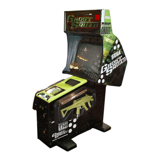
- Page 1 1ST PRINTING FEBUARY ‘05 ® Upright Version Owner’s Manual SEGA AMUSEMENTS USA, INC. MANUAL NO. 999-2306 GAME CODE: CTF...
- Page 2 VISIT OUR WEBSITE! Now with a new look to make your experience that much easier.
- Page 3 BEFORE USING THE PRODUCT, BE SURE TO READ THE FOLLOWING: To maintain the safety: To ensure the safe usage of the product, be sure to read the following before using the product. The following instructions are intended for the users, operators and the personnel in charge of the opera- tion of the product.
- Page 4 SEGA shall not be held responsible for any accidents, compensation for damage to a third party, resulting from the specifications not designated by SEGA.
-
Page 5: Table Of Contents
TABLE OF CONTENTS BEFORE USING THE PRODUCT, BE SURE TO READ THE FOLLOWING: TABLE OF CONTENTS INTRODUCTION OF THE OWNER’S MANUAL 1 - 2 1. HANDLING PRECAUTIONS ..................3 - 4 2. PRECAUTIONS CONCERNING INSTALLATION LOCATION ........5 - 8 3. -
Page 6: Introduction Of The Owners Manual
SEGA AMUSEMENTS USA, INC. / CUSTOMER SERVICE 45133 Industrial Drive, Fremont, California 94538, U.S.A. Phone : (415) 701-6580 Fax : (415) 701-6594 PRODUCTION DATE This SEGA product was produced in the year of: 2005 This signifies that this work was disclosed in 2005. - Page 7 DEFINITION OF LOCATION MAINTENANCE MAN AND SERVICEMAN Non-technical personnel who do not have technical knowledge and expertise should refrain from performing such work that this manual requires the location's main- tenance man or a serviceman to carry out, or work which is not explained in this WARNING! manual.
-
Page 8: Handling Precautions
• SEGA shall not be held responsible for damage, compensation for damage to a third party, caused by specification changes not designated by SEGA. - Page 9 Some parts are the ones designed and manufactured not specifically for this game machine. The manufacturers may discontinue, or change the specific- ations of, such general-purpose parts. If this is the case, Sega cannot repair or replace a failed game machine whether or not a warranty period has expired.
-
Page 10: Precautions Concerning Installation Location
2. PRECAUTIONS CONCERNING INSTALLATION LOCATION This product is an indoor game machine. Do not install it outside. Even indoors, avoid installing in places mentioned below so as not to cause a fire, electric shock, WARNING! injury and or malfunctioning. Places subject to rain or water leakage, or places subject to high humidity in the proximity of an indoor swimming pool and or shower, etc. - Page 11 To avoid machine malfunctioning and a fire, do not place any obstacles near the ventilation opening. SEGA shall not be held responsible for damage, compensation for damage to a third party, resulting from the failure to observe this instruction.
-
Page 12: Operation
3. OPERATION PRECAUTIONS TO BE HEEDED BEFORE STARTING THE OPERATION To avoid injury and trouble, be sure to constantly give careful attention to the behavior and manner of the visitors and players. In order to avoid accidents, check the following before starting the operation: To ensure maximum safety for the players and the customers, ensure that where WARNING! the product is operated has sufficient lighting to allow any warnings to be read. - Page 13 Do not put any heavy item on this product. Placing any heavy item on the prod- uct can cause a falling down accident or parts damage. WARNING! Do not climb on the product. Climbing on the product can cause falling down accidents.
- Page 14 PRECAUTIONS TO BE HEEDED DURING OPERATION(PAYING ATTENTION TO CUSTOMERS) To avoid injury and trouble, be sure to constantly give careful attention to the behavior and manner of the visitors and players. To avoid injury and accidents, those who fall under the following categories are not allowed to play the game.
- Page 15 Immediately stop such violent acts as hitting and kicking the product. Such violent acts can cause parts damage or falling down, resulting in injury due to CAUTION! fragments and falling down. To avoid injury resulting from falling down, immediately stop the customer's leaning against or sitting down on the Gun Holder.
-
Page 16: Assembly And Installation
4. ASSEMBLING AND INSTALLATION ● Perform assembly work by following the procedure herein stated. Failing to comply with the instructions can cause electric shock hazard. WARNING! ● Perform assembling as per this manual. Since this is a complex machine, erroneous assembling can cause an electric shock, machine damage and or not functioning as per specified performance. - Page 17 When carrying out the assembling and installation, follow the following 8-item sequence. INSTALLING THE GD-ROM DRIVE (SETTING GD-ROM DISC) POWER SUPPLY, AND EARTH CONNECTION TURNING POWER ON The master key (accessories) in addition to the tools such as a Phillips type screwdriver, wrench, socket wrench and Ratchet Handle are required for the assembly work.
- Page 18 INSTALLING THE GD-ROM DRIVE (SETTING GD-ROM DISC) ● Carefully handle the GD-ROM drive so as not to contaminate the disc and the readout lens with stains and dust particles. ● Do not continue to use the scratched GD-ROM disc. The scratched GD-ROM disc may cause the system to malfunction.
- Page 19 Remove the 1 truss head screw that fixes the GD-ROM drive lid (DISC LID). And turn clockwise the lid to remove. TRUSS SCREW (1) M3×8 PHOTO 6. 5 b Set the GD-ROM disc onto the GD-ROM drive with its labeled side facing upward. Return the lid to its original place, and fix it with 1 truss head screw.
- Page 20 Place the ASSY MAIN BD on a flat vertical surface. Using the 4 screws, fix the GD-ROM drive onto the ASSY MAIN BD. SCREW (4) M4×16, w/flat & spring washers PHOTO 6. 5 h Insert both the GD cable connector (for data communication) and the power cord connector (JST NH6P) into the GD-ROM drive.
- Page 21 Insert the Key Chip straight into the KEY CHIP hole in the top of the Media Board on the upper part of the Game Board. Carefully check the direc- tion the Key Chip is facing, and push it in as far as it will go. PHOTO 6.
- Page 22 POWER SUPPLY, AND EARTH CONNECTION ● Be sure to independently use the power supply socket outlet equipped with an Earth Leakage Breaker. Using a power supply without an Earth Leakage Breaker can cause a fire when electric leakage occurs. WARNING! ●...
- Page 23 TURNING POWER ON Turn on the AC unit's main switch to connect the power. When the power is connected, the fluorescent light in the billboard becomes on. A few seconds later a system startup screen appears and then an advertising screen (plying for a player screen) appears. Time until displaying an advertising screen is not constant;...
- Page 24 THE INTERFERENCE PREVENTION WIRING ● In order to prevent electric shock and short circuit hazards, be sure to turn power off before performing work. WARNING! ● Be careful not to damage the wires. Damaged wires may cause electric shock or short circuit or present a fire risk. ●...
-
Page 25: Precautions To Be Heeded When Moving The Machine
5. PRECAUTIONS TO BE HEEDED WHEN MOVING THE MACHINE ● When moving the machine, be sure to pull out the plug from the power supply. Moving the machine with the plug as is inserted can cause the power cord to WARNING! be damaged and could result in a fire and or electric shock. -
Page 26: Game Contents
6. GAME CONTENTS The following explanations apply to the case the product is functioning satisfactorily. Should there be any moves different from the following contents, some sort of faults may have occurred. Immediately look into the cause of the fault and eliminate the cause thereof to ensure satisfactory operation. - Page 27 ("Only without the IC Card") is explained separately as needed. (1) GAME OUTLINE The player is a member of the special forces unit, "Ghost Squad", out to suppress vicious terrorists. Each mission contains multiple routes, allowing the player to choose how to proceed. Special events occur throughout the game depending on the route chosen, such as securing hostages or providing friendly cover fire.
- Page 28 (3) CHARACTERS l Alpha Unit The Alpha Unit are the main characters in the game and are young hot-shot members of "Ghost Squad", an unofficial unit of the anti-terrorist group, "M.O.P." (Multiple-Operation-Program) l Fellow M.O.P. Members The Commander provides radio backup and pertinent advice to the Alpha Unit.
- Page 29 (4) GAME FLOW AND ON-SCREEN DISPLAY l Card Insertion Screen [Only with the IC Card] The IC Card Insertion Screen is displayed when starting a game. Insert an IC Card into the card slot to read stored data. To play a game without using an IC Card, select the "Start game without card." panel. IC Card updates are also handled on this screen.
- Page 30 l Customize Screen [Only with the IC Card] On the Customize Screen, weapons and costumes can be changed. With sufficient game progress, name change and screen display type selection also become available. Customize Screen (A)(B) Item Scroll Buttons Scrolls through costume type indicators. Rapid scrolling is possible by keeping it held down.
- Page 31 l Customize Screen [Only without the IC Card] Starting the game without an IC Card will display the following screen and allow weapon and costume selection. l Name Entry Screen When starting a game with a new IC Card, the Name Entry Screen is first displayed. A name chosen once can later be changed on the Customize Screen.
- Page 32 l Gun Controller Explanation Screen Exiting the Customize Menu plays the demo explaining how to use the gun controller. This explains the shooting stance, and how to use the SHOT SELECTOR and ACTION button. It is possible to skip this explanation with the START button. Gun Controller Explanation Screen l Gun Controller Calibration Screen If the CALIBRATION setting in the game Test Mode is turned on, this screen is displayed before starting...
- Page 33 l Mission Select Screen On this screen, the player selects which mission to play from 3 available missions. Playing one mission all the way to the end displays this screen once again, allowing the player to select another mission. A mission played once cannot be played again in the same game. Mission ...
- Page 34 (5) Mission Level : Level of the current mission. (6) Terrorist : Find and suppress! (7) Fellow Troops : Members of the "Ghost Squad". (8) Correspondence : Support requests from fellow troops, or advice from the Commander appears here. (9) Firing Mode : Selectable firing modes and the currently selected firing mode...
- Page 35 l Mission Results Screen [Only with the IC Card] After either successfully completing a single mission or dying partway, the Mission Result Screen is displayed. Mission information, including the route taken or event results, can be confirmed on this screen. This screen also displays a notification if the Mission Level has increased.
- Page 36 (5) GAME RULES AND GAMEPLAY Life During play, the player's life is displayed at the top part of the screen. Life is diminished by enemy attack or accidental fire on hostages. Once the player's life runs out, play stops. The amount of life to start a game with can be configured in Test Mode settings. Changing life settings will not affect the length of the life gauge.
- Page 37 E-Marker When discovered, the terrorists commence fire upon the player. However, not all shots result in injury. An "E-Marker" will be displayed on any enemy whose shots will inflict damage, serving as a warning to the player. When under fire from multiple enemies, first defeating enemies marked with an E-Marker should help the player avoid damage.
- Page 38 The number of selectable tactics will increase along with the Mission Level. Also, a "NEW" label will be displayed on any newly appearing tactics panels. [When no IC Card is being used, the number of Tactics Selection panels will not increase.] Mission level-up Initially only one route Branching routes...
- Page 39 Auxiliary Items Auxiliary items appear in certain situations during the game. There are two types of auxiliary items—items that are put to use and disappear immediately after picking up, and those that are stocked and continue to be effective over time. The latter type can be used only one at a time.
- Page 40 Costumes This game has 14 different costumes. Initially only 2 are available ("GHOST SQUAD" and "JUNGLE"), but that number increases with further play. The chosen costume can be viewed during in-game cut scenes. Costumes have no direct effect on damage, score, or other game content.
- Page 41 Mid-game Entry It is possible for an additional player to join later, even if a player is in the middle of play. If the necessary number of credits has been inserted, a message (as shown below) is displayed on the bottom part of the screen.
- Page 42 (6) IC CARDS [ONLY WITH THE IC CARD] l Number of Uses The number of uses per IC Card is 100. This number includes expenditure for starting or continuing games. An IC Card with 0 remaining uses cannot be used to start a game. However, if the remaining uses reaches 0 during play, it is possible to continue a game.
-
Page 43: Explanation Of Test And Data Display
7. EXPLANATION OF TEST AND DATA DISPLAY By operating the switch unit, periodically perform the tests and data check. When installing the machine initially or collecting cash, or when the machine does not function correctly, perform checking in accordance with the explanations given in this section. The following shows tests and modes that should be utilized as applicable. - Page 44 7-1 SWITCH UNIT AND COIN METER Never touch places other than those specified. Touching places not specified can cause electric shock and short circuit accidents. Adjust the sound to the optimum volume, taking into consideration the environmental requirements of the installation location. Removing the Coin Meter circuitry renders the game inoperable.
- Page 45 7-2 SYSTEM TEST MODE STOP Any settings that are changed by users during TEST MODE are saved upon exiting TEST MODE with the EXIT command in the SYSTEM MENU. If the IMPORTANT! unit is powered off prior to exiting, changes to settings will not take effect. You may not enter GAME TEST MODE while the unit is reading from or checking the GD-ROM.
- Page 46 B. MEDIA BOARD TEST Powering off the system during the MEDIA BOARD TEST with a DIMM BOARD will erase the game programme data. It may be necessary to reload the data. Always wait for the test to complete before attempting to exit. MEDIA BOARD TEST is used to check the memory and IC on the MEDIA BOARD connected to the Chihiro.
- Page 47 C. SYSTEM INFORMATION Use SYSTEM INFORMATION to check version and other information for system programmes. Screens may differ depending on the type of MEDIA BOARD connected to the unit. The following is the SYSTEM INFORMATION screen for a unit with a DIMM BOARD. SYSTEM INFORMATION MAIN BOARD REGION...
- Page 48 D. JVS TEST JVS TEST is used to verify the specs of the I/O BOARD connected to the Chihiro and to run input tests. I/O BOARD specs are displayed initially. Screens may differ depending on the type of I/O BOARD connected to the unit. JVS TEST INPUT TEST NEXT NODE...
- Page 49 INPUT TEST Screen JVS TEST INPUT TEST NODE SYSTEM PLAYER 1 0000 PLAYER 2 0000 COIN 1 0000 COIN 2 0000 ANALOG 1 0000 ANALOG 2 0000 ANALOG 3 0000 ANALOG 4 0000 ANALOG 5 0000 ANALOG 6 0000 ANALOG 7 0000 ANALOG 8 0000 PRESS TEST AND SERVICE BUTTON TO EXIT On-screen values change according to the input from switches and the volume.
- Page 50 E. SOUND TEST Use SOUND TEST to test sound output and to select the stereo/mono/surround setting. SOUND TEST OUTPUT TYPE STEREO RIGHT SPEAKER LEFT SPEAKER EXIT SELECT WITH SERVICE BUTTON AND PRESS TEST BUTTON Use the SERVICE Button to move the cursor to the desired test item. Press the TEST Button to enter the selected item.
- Page 51 F. C.R.T. TEST Use the C.R.T. TEST to adjust monitor colours and verify screen size. COLOUR CHECK Screen Monitor COLOUR CHECK screen is displayed initially. Each of the colours (red, green and blue) is darkest at the far left and gets progressively lighter (32 steps) towards the right.
- Page 52 G. COIN ASSIGNMENTS Use COIN ASSIGNMENTS to set the credit rate for each coin inserted. Use the SERVICE Button to move the cursor to the desired test item. Press the TEST Button to change the setting or to open the detailed settings. Move the cursor to EXIT and press the TEST Button to return to the SYSTEM MENU screen.
- Page 53 COIN TO CREDIT RATE Set the CREDIT RATE for each coin inserted. The "x COIN(S) COUNT AS x CREDIT(S)" setting indicates that "Inserting x coins equals x credits". Set this to "FREE PLAY" to allow game play without credits. When (A) COIN CHUTE TYPE is set to "COMMON", COIN CHUTE #2 settings are restricted to some extent by the settings for COIN CHUTE #1.
- Page 54 GAME COST SETTING Use this mode to set the number of credits required to start a game. Screens may differ depending on the game. COIN ASSIGNMENTS GAME COST SETTING 1 CREDIT TO START 1 CREDIT TO CONTINUE EXIT SELECT WITH SERVICE BUTTON AND PRESS TEST BUTTON Set the number of credits required to start a game.
- Page 55 H. CLOCK SETTING Use CLOCK SETTING to set the Chihiro internal clock. CLOCK SETTING 2002/11/15(FRI) 05:10:34 YEAR MONTH HOUR MINUTE EXIT SELECT WITH SERVICE BUTTON AND PRESS TEST BUTTON Use the SERVICE Button to move the cursor to the item to be set. Move the cursor to the desired item and press the TEST Button to increase values.
- Page 56 I. NETWORK SETTING (CORE) Use the LAN PORT attached to the Main Board, and carry out the settings necessary for network communication. Note: This function is not available with this product. NETWORK SETTING (CORE) ->REMOTE(C) ENABLE IP ADDRESS(C) ---.---.---.--- SUBNET MASK(C) ---.---.---.--- GATE WAY(C) ---.---.---.---...
- Page 57 J. NETWORK SETTING (MEDIA) Use NETWORK SETTING to establish and test network connections. This is only displayed the following error message screen. • This game does not support network communication connections. NETWORK SETTING(MEDIA) COMMUNICATION ERROR www.seuservice.com...
- Page 58 7-3 GAME TEST MODE STOP When changing the game configuration, changes will not take effect until the Game Test Mode has been completed. Be sure to exit the Game Test Mode IMPORTANT! properly after configuration changes. Do not configure the game in ways not described in this text. It is possible that the game will not function properly.
- Page 59 A. INPUT TEST Select INPUT TEST to display the following screen and check the status of input devices. This test should be used periodically to check that each input device is functioning correctly. INPUT TEST PLAYER TRIGGER ACTION CHANGE CARD IN GUN-X GUN-Y SCREEN...
- Page 60 B. OUTPUT TEST Select OUTPUT TEST to display the following screen and check the status of each lamp. This test should be used periodically to check that the lamps are functioning correctly. Press the SERVICE Button to move the cursor and the TEST Button to select. Displays ON when selected.
- Page 61 C. GAME ASSIGNMENTS Select GAME ASSIGNMENTS to display the current game settings and make changes. GAME ASSIGNMENTS DIFFICULTY NORMAL LIFE REACTION CALIBRATION ADVERTISE SOUND ON CARD -> EXIT SELECT WITH SERVICE BUTTON AND PRESS TEST BUTTON FIG. 9. 3 c GAME ASSIGNMENTS screen Perform the following settings for each item.
- Page 62 D. GUN ADJUSTMENT Select GUN ADJUSTMENT to display the following screen. This screen allows you to adjust the gun using the five calibration targets (TOP, LEFT, CENTER, RIGHT, BOTTOM). Use each target to calibrate as follows. Use the standard gun controller, carefully aim at the correct target and pull the trigger to calibrate the value.
- Page 63 Details for each item are as follows. l TOP x y: Set the TOP value. The number on the left (x) is the horizontal component, and the number on the right (y) is the vertical component. Aim the controller at the TOP target (circle) and pull the trigger to set the value.
- Page 64 e. BOOKKEEPING Select BOOKKEEPING on the Game Test Menu screen to display the three screens of operating status data. BOOKKEEPING PAGE1/3 COIN 1 COIN 2 TOTAL COINS COIN CREDITS SERVICE CREDITS TOTAL CREDITS PRESS TEST BUTTON TO CONTINUE The display items for the screen (Page 1 of 3) are as follows. COIN 1: The number of coins inserted into Coin Slot 1.
- Page 65 Press the TEST Button to display the next screen. BOOKKEEPING PAGE2/3 NUMBER OF GAMES TOTAL TIME 0D 0H 0M 0 S PLAY TIME 0D 0H 0M 0S AVERAGE PLAY TIME 0M 0S LONGEST PLAY TIME 0M 0S SHORTEST PLAY TIME 0M 0S PRESS TEST BUTTON TO CONTINUE The display items for the screen (Page 2 of 3) are as follows.
- Page 66 f. BACKUP DATA CLEAR Select BACKUP DATA CLEAR to clear the contents of BOOKKEEPING and Score Data. BACKUP DATA CLEAR YES(CLEAR) -> NO (CANCEL) SELECT WITH SERVICE BUTTON AND PRESS TEST BUTTON BACKUP DATA CLEAR Screen To clear data, use the SERVICE Button to move the cursor to YES (CLEAR) and then press the TEST Button.
-
Page 67: Control Unit (Gun Controller)
10. CONTROL UNIT (GUN CONTROLLER) l In order to prevent any electric shocks or short circuits, be sure to turn the power off before performing any work that involves touching the interior parts of the product. WARNING! l Be careful not to damage the wires. Damaged wires may cause electric shocks or short circuits, or present a risk of fire. - Page 68 REPLACING THE MICROSWITCH To replace the Gun Controller's internal components, first separate the left shell (Cover L) and right shell (Cover R). The controller's internal components are mounted on the right shell, so work with the gun lying on its right side. To replace the Shot Selector button microswitch, first remove the Shot Selector button from the right shell.
- Page 69 l With the right shell lying flat, carefully lift the left shell from the right shell. COVER L COVER R PHOTO 10 b l Remove the microswitch to be replaced from Cover R. There are a total of three microswitches. MICROSWITCH 509-5080 PHOTO 10 c...
- Page 70 l Solder the new microswitch in place to reconstruct the gun controller. When performing this step, verify the points listed below before reattaching Cover L and Cover R. lThe wires and connectors are laid out correctly in Cover R. lThe bearing holder is securely in place when the pad assembly spring is compressed. lThe selector is laid out horizontally.
- Page 71 l Operate the TRIGGER, SHOT SELECTOR and ACTION buttons to make sure that the microswitches turn ON/OFF correctly. SHOT SELECTOR ACTION BUTTON TRIGGER FIG. 10 c l After replacement, perform an INPUT TEST, referring to the instructions in "Game Test Mode". www.seuservice.com...
- Page 72 REPLACING THE SENSOR UNIT l Follow instructions of "Replacing the Microswitch" to remove the cover L. l Remove the connector to replace the sensor unit. SENSOR UNIT JPT-2030 Remove the connector. PHOTO 10 f l Refer to the previous item, then attach COVER R while being careful of each of the parts. l After replacement, perform a GUN ADJUSTMENT, referring to the instructions in "Game Test Mode".
- Page 73 l Remove the 2P connector, wire and 4 screws to take off the solenoid assembly. Remove the connector. SOLENOID ASSEMBLY SCREW (4) WIRE M3×6, w/spring washer PHOTO 10 g l Remove the 8 screws and replace the solenoid. SCREW (8) M3×6, w/spring washer SOLENOID PHOTO 10 h...
-
Page 74: Monitor
WARNING! Using the monitor by converting it without obtaining a prior permission is not allowed. SEGA shall not be liable for any malfunctioning and accident caused by said conversion. Primary side and Secondary side... - Page 75 For the purpose of static prevention, special coating is applied to the CRT face of this product. To protect the coating, pay attention to the following points. Damaging the coating film can cause electric shock to the customers. Do not apply or rub with a hard item (a rod with pointed edge, pen, etc.) to or on the CRT surfaces.
- Page 76 SANWA Monitor: 998-0162 (31K Mode) CONTRAST BRIGHT H SIZE H POSI V SIZE V POSI CONTRAST ....Adjust image contrast. BRIGHT ...... Controls screen brightness. H. SIZE ......Controls horizontal screen size. H. POSI ......Controls horizontal display position on screen. V. SIZE ......Controls vertical screen size.
-
Page 77: Coin Selector
10. COIN SELECTOR HANDLING THE COIN JAM If the coin is not rejected when the REJECT button is pressed, open the coin chute door and open the selector gate. After removing the jammed coin, put a normal coin in and check to see that the selector correctly functions. - Page 78 www.seuservice.com...
- Page 79 COIN DOOR www.seuservice.com...
-
Page 81: Parts
12. PARTS ASSY CONTROLLER HOLDER (CTF-1300) Fastening Torque: : 1.4N•m(14kgf•cm) ITEM NO. PART NO. DESCRIPTION NOTE CTF-1340 ASSY HOLDER LIGHT CTF-1301 CONTROLLER HOLDER L CTF-1302 CONTROLLER HOLDER PLATE L CTF-1303 CONTROLLER HOOK CTF-1002 WASHER CTF FAS-290037 HEX SKT LH CAP SCR SCR STN M5X20 FAS-120031 TAP SCR P-TITE TH BLK 4X16 www.seuservice.com... - Page 82 ASSY CONTROLLER HOLDER (CTF-1320) Fastening Torque: : 1.4N•m(14kgf•cm) ITEM NO. PART NO. DESCRIPTION NOTE CTF-1340 ASSY HOLDER LIGHT CTF-1321 CONTROLLER HOLDER R CTF-1322 CONTROLLER HOLDER PLATE R CTF-1303 CONTROLLER HOOK CTF-1002 WASHER CTF FAS-290037 HEX SKT LH CAP SCR SCR STN M5X20 FAS-120031 TAP SCR P-TITE TH BLK 4X16 www.seuservice.com...
- Page 84 2 GAME BOARD AREA ITEM NO. PART NO. DESCRIPTION NOTE 998-0165 GUN INPUT PROTECTION CIRCUIT 838-13143-08 IC BD GUN SENSE SPY 560-5407-UL TRANSFORMER AUDIO 838-13616 AUDIO POWER AMP 2 CH www.seuservice.com...
- Page 85 3 OTHER PARTS ITEM NO. PART NO. DESCRIPTION NOTE 999-1656 PUSH BUTTON 1 1/2” YELLOW START 1 999-1657 PUSH BUTTON 1 1/2” YELLOW START 2 999-0167 LEG LEVELER 1/2-13-3” 999-0168 CASTER 160-2 1/2 #251888 SWIVEL LOCAL PURCHASE FLUORESCENT LAMP ASSY 24” COOLWHITE 999-1442 SPEAKER 4 OHM 15 WATT JPT-1082...
- Page 86 CONTROL UNIT (CTF-2100) (D-1/2) www.seuservice.com...
- Page 87 CONTROL UNIT (CTF-2100) (D-2/2) ITEM NO. PART NO. DESCRIPTION NOTE JPT-2030 SENSOR UNIT CTF-2101 COVER L CTF-2102 COVER R CTF-2103 FRONT SIGHT CTF-2104 MAIN TRIGGER CTF-2105 SUB TRIGGER CTF-2106 SELECTOR CTF-2107 SELECTOR HOLDER CTF-2108 SELECTOR JOINT CTF-2109 PAD BASE CTF-2110 BEARING HOLDER CTF-2111 CTF-2112...
-
Page 88: Wire Color Code Table
13. WIRE COLOR CODE TABLE THE WIRE COLOR CODE is as follow: PINK SKY BLUE BROWN PURPLE LIGHT GREEN Wires other than those of any of the above 5 single colors will be displayed by 2 alphanumeric characters. BLUE YELLOW GREEN WHITE ORANGE... - Page 89 White text www.seuservice.com...
- Page 90 Notes:...
- Page 91 Warranty Your new Sega Product is covered for a period of 90 days from the date of shipment. This certifies that the Printed Circuit Boards, Power Supplies and Monitor are to be free of defects in workman- ship or materials under normal operating conditions. This also certifies that all Interactive Control Assemblies are to be free from defects in workmanship and materials under normal operating condi- tions.
- Page 92 SEGA AMUSEMENTS USA, INC.
Need help?
Do you have a question about the GHOST SQUAD and is the answer not in the manual?
Questions and answers