
Related Manuals for Hangar 9 Cub Crafters XCub 60cc


Summary of Contents for Hangar 9 Cub Crafters XCub 60cc
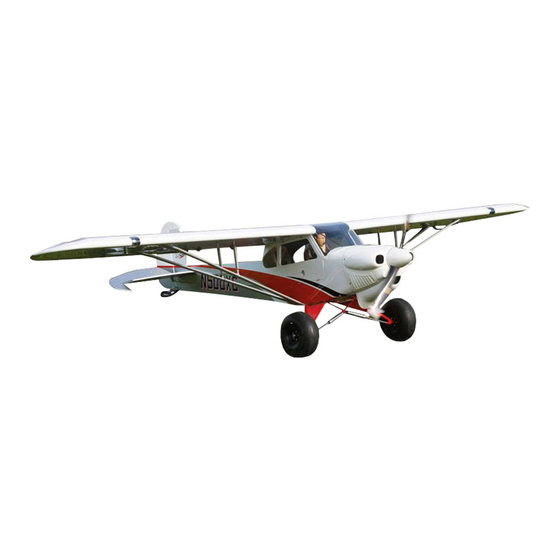
- Page 1 Cub Crafters XCub 60cc Instruction Manual Bedienungsanleitung Manuel d’utilisation Manuale di Istruzioni...
- Page 2 SPECIFICATIONS • SPEZIFIKATIONEN • SPÉCIFICATIONS • SPECIFICHE 2-Stroke Gas: 50cc–70cc, 4-Stroke gas/petrol: 61cc Spinner: 4-inch (Included) 116.0 in (294 cm) 2-Takt Benziner: 50cc–70cc, 4-Takt Benzin: 61 cc Spinner: 102mm (Enthalten) 2 temps Essence: 50cc–70cc, 4 temps essence: 61cc Cône: 102mm (Fourni) 1908 sq in (123.1 dm2) Total 2-Tempi Gas: 50cc–70cc, 4 tempi benzina: 61 cc Ogiva dell’elica: 102mm (Inclusa)
- Page 3 Moteur à gaz/essence 62GX 62 cc Motore benzina 62GX 62cc HAN116 Fuel Filler with “T” and Overfl ow Fitting Hangar 9 Tanknippel mit T Stück u. Überlauf Fitting Point de remplissage de carburant avec coupleur en T Bocchettone di riempimento carburante con SPMA3002 Heavy-Duty Servo Extension 9-inch Servokabelverlängerung 230 mm (9 inch)
- Page 4 Part # English Deutsch Français Italiano REQUIRED TOOLS • BENÖTIGTES WERKZEUG • OUTILS REQUIS • ATTREZZI NECESSARI Box wrench: 12mm, 1/2-inch Ringschlüssel: 12mm, 1/2-inch Clé hexagonales: 12mm, 1/2-inch Chiavi: 12mm, 1/2-inch Drill Bohrer Mini-perceuse Trapano Drill bits: 5/64-inch, 3/32-inch, 7/64-inch, Punte per trapano: 1,5 mm, 2mm, 2,5mm, 3mm, Bohrer: 1,5 mm, 2mm, 2,5mm, 3mm, 3,5mm, 5mm Forêt : 1,5 mm, 2mm, 2,5mm, 3mm, 3,5mm, 5mm...
-
Page 5: Optional Scale Accessories
Custom markings and decals: Maßstabsgetreue Instrumententafeln: www.callie-graphics.com Marquages et autocollants personnalisés : Contrassegni e decalcomanie personalizzati: www.ifl ytailies.com Scale Propellers: www.callie-graphics.com www.callie-graphics.com www.aircraftinternational.com Hélices à échelle : Eliche in scala: Kundenspezifi sche Markierungen und Decals: www.aircraftinternational.com www.aircraftinternational.com www.callie-graphics.com Maßstabgetreue Propeller: www.aircraftinternational.com Cub Crafters XCub 60cc... -
Page 6: Before Starting Assembly
NOTICE Batteries Always follow the manufacturer’s instructions when using and disposing of any batteries. Mishandling of Li-Po All instructions, warranties and other collateral documents are subject to change at the sole discretion of Horizon batteries can result in fi re causing serious injury and damage. Hobby, LLC. -
Page 7: Vor Dem Zusammenbau
Fliegen Fliegen Sie um Sicherheit garantieren zu können, nur in weiten offenen Gegenden. Wir empfehlen hier den Betrieb auf zugelassenen Modellfl ugplätzen. Bitte beachten Sie lokale Vorschriften und Gesetze, bevor Sie einen Platz zum Fliegen wählen. Cub Crafters XCub 60cc... -
Page 8: Avant De Commencer L'assemblage
REMARQUE L’hélice Gardez éloignés tous les éléments qui pourraient être attrapés par l’hélice. Cela inclut les vêtements larges ou les La totalité des instructions, garanties et autres documents est sujette à modifi cation à la seule discrétion d’Horizon objets comme des outils par exemple. Gardez toujours vos mains à distance pour éviter tout cas de blessures. Hobby, LLC. -
Page 9: Precauzioni Per La Costruzione
Horizon Hobby di competenza. Volo Per sicurezza volare solo in aree molto ampie. Meglio se in campi volo autorizzati per modellismo. Consultare le ordinanze locali prima di scegliere luogo dove volare. Cub Crafters XCub 60cc... - Page 10 REMOVING WRINKLES ENTFERNEN VON FALTEN ÉLIMINATION DES PLIS TOGLIERE LE GRINZE The covering of your model may develop wrinkles during Während des Transportes können bei der Bespannung L’entoilage de votre modèle peut développer des plis rivestimento di questo modello potrebbe sviluppare delle shipping and will require the use of a heat gun (HAN100) Falten aufgetreten sein.
-
Page 11: Control Horn Installation
Check that the horn is 90-degrees to the surface of the 10. Insert the rudder control horn in the rudder. The tabs on the aileron. If not, lightly trim the hole in the aileron to reposition horn will rest against the rudder. the control horn. Cub Crafters XCub 60cc... -
Page 12: Aileron Servo Installation
AILERON SERVO INSTALLATION 11. Use a felt-tipped pen to mark the control horn on both sides of the rudder. This will indicate the area of the control horn 16. Remove the aileron servo cover from the wing. Tape the string where the paint must be removed. - Page 13 Connect the radio system to the servo and center the servo. Adjust the linkage as necessary to center the aileron when the servo is centered. Repeat this section for the remaining aileron servo. Cub Crafters XCub 60cc...
-
Page 14: Flap Servo Installation
FLAP SERVO INSTALLATION 36. When attaching the linkage to the servo arm, use the hole in the arm that is 5/8-inch (16mm) from the center of the arm. 31. Center the servos and install the servo arms on the servos Enlarge this hole using a pin vise and 1/8-inch (3mm) drill bit. -
Page 15: Wheel Assembly
50. Align the hub so the holes in the center align with the notches 45. Move the switch at the transmitter to the “FULL” fl ap position in the tire. of 2 inches (70mm). Adjust the radio settings to achieve the setting for full fl ap. Cub Crafters XCub 60cc... - Page 16 51. Place the nylon bushing in position in the center of the cover. 56. Secure the axle bolt to the landing gear using the axle bolt lock nut. Use a 6mm hex wrench and 1/2-inch nut driver to tighten the hardware. Once tightened, make sure the wheel can spin freely on the axle bolt.
- Page 17 70. Slide the axle into the wheel hub from the lettered side of the socket head cap screws. Place a drop of threadlock on each wheel. screw before placing them into position. Use a 2.5mm hex wrench to tighten the screws. Cub Crafters XCub 60cc...
-
Page 18: Wing And Wing Strut Installation
71. Slide the axle into the main landing gear. Place a drop 75. Attach the strut fi tting near the aileron to the bottom of the of threadlock on the two M3 x 3 setscrews. Thread the wing using two M3 x 15 socket head cap screws. Apply a setscrews into the gear, tightening them on the fl... - Page 19 Thread an M3 x 15 socket head cap screw into each of the blind nuts. If any of the screws are difficult to thread in, use a 3mm tap and tap handle to clear the threads. Cub Crafters XCub 60cc...
-
Page 20: Stabilizer Installation
89. Cut two pieces of card stock that are 1/2 x 2 inches (13 x 94. Fit the fairing back on the strut. Attach the struts to the 25mm). Make a 1/8-inch (3mm) hole in each piece. Tape the fuselage, then attach the fairing to the fuselage using two M3 card stock to the fuselage with the hole aligned with the blind x 15 socket head cap screws and two M3 washers. -
Page 21: Fin Installation
108. Use a felt-tipped pen to transfer the outline of the fi n onto the epoxy. Use an epoxy brush to apply epoxy to the exposed top of the fuselage. wood on the top and bottom of the stabilizer. Cub Crafters XCub 60cc... - Page 22 109. Use a ruler and carefully cut the covering 1/8 inch (3mm) 114. Fit the fi n back into position. Continually check the alignment below the line drawn on the fi n to remove the covering. of the fi n to the stabilizer as the epoxy cures. Remove the covering from both sides of the fi...
-
Page 23: Radio Installation
128. Install the rudder and elevator servos in the fuselage. Make sure to prepare the servos with the grommets and eyelets. The mounting holes will need to be drilled and prepared before the screws can be installed. The rudder servo is the center servo. Cub Crafters XCub 60cc... -
Page 24: Rudder Pull-Pull Cable Installation
RUDDER PULL-PULL CABLE INSTALLATION 129. Install the receiver in the fuselage. Mount any remote receivers in the fuselage using hook and loop tape. Follow 134. Thread a ball end eight turns on each of the four cable the instructions included with the receiver for the correct fi... -
Page 25: Elevator Linkage Installation
Tighten the hardware using a 2.5mm hex wrench hardware using a 2.5mm hex wrench and 5.5mm nut driver. and 5.5mm nut driver. Install both remaining rod ends. Do not over-tighten the hardware and damage the control horn or ball end. Cub Crafters XCub 60cc... -
Page 26: Tail Wheel Installation
148. Slide the elevator pushrod into the pushrod tube. Use the 153. Secure the wheel using the M4 locknut. Use a 3mm hex radio system to center the elevator servo. Install the servo wrench and 7mm nut driver to tighten the hardware. Make arm so it is 90 degrees to the pushrod. -
Page 27: Tail Bracing Installation
Trim any excess cable using side cutters. Install tabs on the left and right of the stabilizer, and near the top of the fin. Do not overtighten the hardware and compress the wood structure of the stabilizer or fin. Cub Crafters XCub 60cc... -
Page 28: Electric Motor Installation
168. Once all the cables have been installed, check the tension on 172. Attach the motor box to the fuselage using four M5 x 20 the cables. There should be light tension on the cables. Slide socket head cap screws and four M5 washers. Place a drop the retainer over the forks of the clevis. -
Page 29: Gas Engine Installation
Tie wraps can also be used to secure the installation of the cowling. fuel lines as an alternative to wire ties. Cub Crafters XCub 60cc... - Page 30 ® Motor installation other than the Evolution 62GX: 191. Attach the clevis to the throttle servo arm following the instructions provided with the engine. Check the operation The measurement from the fi rewall to the drive washer should of the throttle using the radio system. Make any adjustments measure 7 inches (191mm).
-
Page 31: Seat Installation
When correctly adjusted, the seat will fit securely, but still be removable when needed. Cub Crafters XCub 60cc... -
Page 32: Cowling Installation
COWLING INSTALLATION 204. Tape the front window in position. Mark the window at the division between the top hatch and fuselage. 209. Cut four pieces of card stock that are 1/2 x 2 inches (13 x 51mm). Make a 1/8-inch (3mm) hole in each piece. Tape the card stock to the fuselage with the hole aligned with the blind nut in the fuselage. -
Page 33: Propeller And Spinner Installation
216. Use the four M2.5 x 10 socket head cap screws to secure the 221. Attach the spinner cone using the four M2.5 x 10 socket head spinner cone to the back plate. Use a 2mm hex wrench to cap screws and a 2mm hex wrench. tighten the screws. Cub Crafters XCub 60cc... - Page 34 TOW HOOK INSTALLATION (OPTIONAL) 227. Center the tow release servo and place the servo arm on the servo perpendicular to the servo centerline. 222. Remove the covering from the fuselage for the tow hook release using a hobby knife and #11 blade. Mount the tow hook release in the top of the fuselage.
-
Page 35: Decal Installation
Allow the model to rest overnight so the remaining water can evaporate. Custom decals are available for those wanting to make their Cub Crafters XCub more unique. One such source of custom graphics is callie-graphics.com. Cub Crafters XCub 60cc... -
Page 36: Center Of Gravity
CENTER OF GRAVITY CONTROL THROWS An important part of preparing the aircraft for fl ight is properly balancing the model. The Center of Gravity range Turn on the transmitter and receiver of your model. Check the movement of the rudder using the transmitter. supplied here is a guideline based on testing. -
Page 37: Preflight Checklist
Product Support Inquiry, or call the toll free telephone PROVIDED UNDER THIS WARRANTY IS THE PURCHASER’S number referenced in the Warranty and Service Contact SOLE AND EXCLUSIVE REMEDY. Information section to speak with a Product Support representative. Cub Crafters XCub 60cc... -
Page 38: Warranty And Service Contact Information
WARRANTY AND SERVICE CONTACT INFORMATION Inspection or Services Warranty Requirements If this Product needs to be inspected or serviced and is For Warranty consideration, you must include your compliant in the country you live and use the Product original sales receipt verifying the proof-of-purchase Country in, please use the Horizon Online Service Request date. -
Page 39: Montage Des Steuerhorns
10. Das Seitenruder-Steuerhorn auf dem Seitenruder montieren. Prüfen, dass das Horn im Winkel von 90 Grad zur Die Laschen am Horn werden gegen das Seitenruder liegen. Querruderoberfl äche steht. Falls nicht, das Loch im Querruder leicht trimmen, um das Steuerhorn neu zu positionieren. Cub Crafters XCub 60cc... -
Page 40: Montage Des Querruder-Servo
MONTAGE DES QUERRUDER-SERVO 11. Mit einem Filzstift das Steuerhorn auf beiden Seiten des Seitenruders markieren. Dadurch wird der Bereich angezeigt, 16. Die Servoabdeckung des Querruders von der Tragfl äche von dem die Farbe entfernt werden muss. entfernen. Den Faden mit Klebeband an der Tragfl äche befestigen, damit er nicht in die Tragfl... - Page 41 Servoarm mit der mit dem Servoarm mitgelieferten Hardware anbringen. Das Funksystem am Servo anschließen und Servo zentrieren. Das Gestänge nach Bedarf anpassen, um das Querruder zu zentrieren, wenn der Servo zentriert ist. Diesen Abschnitt für den verbleibenden Querruder-Servo wiederholen. Cub Crafters XCub 60cc...
- Page 42 INSTALLATION DES KLAPPEN-SERVOS 36. Beim Anbringen des Gestänges am Servoarm das Loch im Arm verwenden, das 16 mm (5/8 Zoll) von der Mitte des Arms 31. Die Servos zentrieren und die Servoarme auf den Servos entfernt liegt. Dieses Loch mit einem Feilkloben und 3 mm senkrecht zur Mittellinie des Servos montieren.
-
Page 43: Montage Der Räder
45. Den Schalter auf dem Sender in die Klappenposition „FULL“ Kerben am Rad ausgerichtet sind. [Komplett ausgefahren] von 70 mm (2 Zoll) bewegen. Die Einstellungen des Funksystems anpassen, um die Einstellung für die komplett ausgefahrene Klappenposition zu erreichen. Cub Crafters XCub 60cc... - Page 44 51. Das Nylon-Lager in der Mitte der Abdeckung platzieren. 56. Den Achsbolzen am Fahrwerk mit der Kontermutter des Achsbolzens sichern. Mit einem 6 mm Sechskant und einem 12,7 mm (1/2 Zoll) Steckschlüssel die Hardware festziehen. Nach dem Festziehen sicherstellen, dass sich das Rad frei auf dem Achsbolzen drehen kann.
- Page 45 Griff die Gewinde gängig machen. Buchstaben schieben. 65. Die Strebenhalterung am Rumpf mit zwei M3 x 15 Zylinderkopfschrauben anbringen. Vor dem Einsetzen der Schrauben einen Tropfen Gewindesicherung auf jede Schraube geben. Mit einem 2,5 mm Sechskant die Schrauben festziehen. Cub Crafters XCub 60cc...
- Page 46 71. Die Achse auf das Hauptfahrwerk schieben. Einen Tropfen 74. Eine M3 x 15 Zylinderkopfschraube auf jede Blindmutter Gewindesicherung auf die zwei M3 x 3 Feststellschraube auf der Unterseite der Tragfl äche schrauben. Lässt sich eine auftragen. Die Feststellschrauben auf das Fahrwerk der Schrauben nur schwer schrauben, mit einem 3 mm schrauben und diese auf der fl...
- Page 47 87. Die inneren Strebenverkleidungen ausfi ndig machen. Es gibt Verkleidung können gleichzeitig montiert werden. eine linke und eine rechte Verkleidung. Die Passung einer jeden Verkleidung überprüfen, um sicherzustellen, dass sie auf der korrekten Rumpfseite montiert sind. Cub Crafters XCub 60cc...
- Page 48 88. Mit einem Nr. 1 Kreuzschlitzschraubendreher oder 93. Die Streben trennen und die Verkleidung entfernen. Mit Zahnstocher die Abdeckung entfernen, um die zum Sichern einem Feilkloben und einem 3 mm (1/8 Zoll) Bohrer die der Verkleidung am Rumpf verwendeten Blindmuttern Befestigungslöcher in die Verkleidung bohren. freizulegen.
- Page 49 Hinterkante des Seitenleitwerks mit dem Rumpf ausrichten. zu schneiden, was zur Schwächung des Stabilisators führen würde. 102. Mit einem Papiertuch und Isopropylalkohol sämtliche Linien 107. Mit einem Filzstift den Umriss des Rumpfs auf das vom Stabilisator entfernen. Seitenleitwerk übertragen. Cub Crafters XCub 60cc...
- Page 50 108. Mit einem Filzstift den Umriss des Seitenleitwerks auf die 113. Mit einer Epoxidbürste das Epoxid auf das freigelegte Holz auf Oberseite des Rumpfs übertragen. der Unterseite des Seitenleitwerks auftragen. 109. Mit einem Lineal vorsichtig die Abdeckung 3 mm (1/8 Zoll) 114.
-
Page 51: Montage Des Funkgeräts
Epoxid muss vor dem Fortfahren vollständig ausgehärtet sein. ist. MONTAGE DES FUNKGERÄTS 122. Die Schnur im Seitenruder an die Leitung für das Positionslicht mit Klebeband kleben. 127. Die Abdeckung des Funkgeräts vom Rumpf entfernen und an einem sicheren Ort ablegen. Cub Crafters XCub 60cc... - Page 52 128. Die Servos von Seitenruder und Höhenruder im Rumpf 133. Den Boden entfernen und zur Seite legen.Die Leitungen für montieren. Sicherstellen, die Servos mit den Hülsen und Querruder und Klappen durch den Cockpitboden verlegen. Ösen vorzubereiten. Die Befestigungslöcher müssen gebohrt Die Leitungen mit Kabelbinder, Klebeband oder jeder anderen und vorbereitet werden, ehe die Schrauben montiert werden bevorzugten Methode sichern, damit sie den Betrieb des...
- Page 53 Arm verwenden, das 16 mm (5/8 Zoll) von der Mitte des Arms Für die nachfolgenden Schritte sollte das Funksystem entfernt liegt. Dieses Loch mit einem Feilkloben und 3 mm eingeschaltet und der Seitenruder-Servo zentriert sein. (1/8 Zoll) Bohrer vergrößern. 5/8 inch (16mm) Cub Crafters XCub 60cc...
-
Page 54: Montage Des Spornrads
MONTAGE DES SPORNRADS 147. Den Kugelkopf am Servoarm mit einer M3 x 12 Zylinderkopfschrauben, M3 Kontermutter und M3 152. Mit der mit dem Spornrad mitgelieferten Hardware das Rad Unterlegscheibe anbringen. Die Hardware mit einem 2,5 mm in der Gabel sichern. Die Abstandhalter aus Messing befi nden Sechskant und einem 5,5 mm Steckschlüssel festziehen. -
Page 55: Montage Der Heckverspannung
Maschinenschraube schieben. Die Schraube durch das Loch Manschette führen. Eine leichte Spannung auf das Kabel auf der Oberseite des Stabilisators schieben. bringen, dann die Manschette mit einer Crimpzange am Kabel sichern. Das überstehende Kabel mit einem Seitenschneider abschneiden. Cub Crafters XCub 60cc... -
Page 56: Montage Des Elektromotors
166. Eine Manschette auf das Kabel schieben, das Kabel durch Montage eines anderen Motors als Power 360: das Öhr nahe der Oberseite des Seitenleitwerks schieben. Der Abstand vom Brandschott bis zur Unterlegscheibe des Motors Das Kabel geht dann wieder durch die Manschette. Die sollte 191 mm (7 Zoll) betragen. - Page 57 Ein dünnes Stück Schaumstoff zwischen Tank und 179. Die Pendel in den Kraftstofftank einführen. Erst das große Motorhalterung wird verhindern, dass der Tank nach der Pendel und dann das kleinere Pendel montieren. Montage im Rumpf verrutscht. Cub Crafters XCub 60cc...
- Page 58 185. Den Motor mit vier M5 x 20 Zylinderkopfschrauben und vier 189. Den Gas-Servo im Rumpf montieren, wobei der Ausgang zur M5 Unterlegscheiben am Rumpf anbringen. Vor der Montage Vorderseite des Rumpfs weist. Sicherstellen, den Servo und der Schrauben einen Tropfen Gewindesicherung auf jede die Montagelöcher laut der Beschreibung in dieser Anleitung Schraube geben.
- Page 59 Es kann erforderlich sein, die Anpassung dieser Schrauben und den Probeeinbau des Sitzes ein paar Mal durchzuführen, ehe die korrekte Höhe der Schrauben erreicht ist. Der Sitz wird bei korrekter Anpassung sicher sitzen, kann bei Bedarf aber immer noch entfernt werden. Cub Crafters XCub 60cc...
-
Page 60: Montage Der Motorhaube
202. Mit Kanzelkleber oder Kontaktklebstoff die Fenster im 207. Die verbleibende Windschutzscheibe auf der Rumpf sichern. Mit einem Klebeband mit geringer Klebekraft Kanzelabdeckung positionieren. Das Loch im durchsichtigen die Fenster in Position halten, bis der Kleber vollständig Material ist mit der Schraube auf der Rückseite des ausgehärtet ist. - Page 61 Propeller mit Ein Standbohrmaschine wird zum Bohren der Löcher den Aussparungen im Spinnerkegel ausgerichtet ist. empfohlen, um zu garantieren, dass die Löcher bei der Montage des Propellers korrekt ausgerichtet sind. Cub Crafters XCub 60cc...
- Page 62 220. Den Motor drehen, damit er gegen Kompression ist. Den 225. Beim Anbringen des Gestänges am Servoarm das Loch im Propeller in Bezug auf Kompression in die bevorzugte Position Arm verwenden, das 16 mm (5/8 Zoll) von der Mitte des Arms bringen. Zum Anbringen des Propellers die mit dem Motor entfernt liegt.
- Page 63 überfl üssiges Wasser unter dem Decal entfernen. Das Modell über Nacht ruhen lassen, sodass das verbleibende Wasser verdunsten kann. Kundenspezifische Decals sind für diejenigen verfügbar, die den Cub Crafters XCub einzigartiger gestalten möchten. Eine derartige Quelle für kundenspezifi sche Grafi ken ist callie-graphics.com. Cub Crafters XCub 60cc...
- Page 64 SCHWERPUNKT RUDERAUSSCHLAG Ein wichtiger Teil bei der Vorbereitung des Flugzeugs für den Flug ist das ordnungsgemäße Ausbalancieren des Den Sender und Empfänger des Modells einschalten. Die Bewegung des Seitenruders mit dem Empfänger prüfen. Modells. Der hier aufgeführte Schwerpunktbereich dient basierend auf Tests als Richtlinie. Abweichungen von Wird der Hebel nach rechts bewegt, sollte sich auch das Seitenruder nach rechts bewegen.
-
Page 65: Täglicher Flug Check
(c) Ansprüche des Käufers ¬ Es liegt ausschließlich zurückzugeben. im Ermessen von Horizon, ob das Produkt, bei dem ein Garantiefall festgestellt wurde, repariert oder ausgetauscht wird. Dies sind die exklusiven Ansprüche des Käufers, wenn ein Defekt festgestellt wird. Cub Crafters XCub 60cc... -
Page 66: Garantie Und Service Kontaktinformationen
Sicherheitshinweise Fragen, Hilfe und Reparaturen Bitte legen Sie dem Produkt einen Kaufbeleg bei, sowie ACHTUNG: Kostenpfl ichtige Reparaturen nehmen wir Dieses ist ein hochwertiges Hobby Produkt und kein Ihr lokaler Fachhändler und die Verkaufstelle können eine ausführliche Fehlerbeschreibung und eine Liste aller nur für Elektronik und Motoren vor. -
Page 67: Installation Du Renvoi De Commande
Vérifi ez que le renvoi est à 90 degrés de la surface de gouverne. Les volets sur le renvoi sont positionnés contre la l’aileron. Si ce n’est pas le cas, compensez légèrement le trou gouverne. de l’aileron pour repositionner le renvoi de commande. Cub Crafters XCub 60cc... -
Page 68: Installation Du Servo De L'aileron
INSTALLATION DU SERVO DE L’AILERON 11. Utilisez un stylo-feutre pour marquer le renvoi de commande des deux côtés de la gouverne. Cela permet d’indiquer la 16. Retirez le cache du servo de l’aileron de l’aile. Collez la fi celle zone du renvoi de commande où... - Page 69 Branchez le système radio au servo, puis centrez le servo. Ajustez la tringlerie comme nécessaire de manière à centrer l’aileron lorsque le servo est centré. Répétez cette partie pour le servo d’aileron restant. Cub Crafters XCub 60cc...
- Page 70 INSTALLATION DU SERVO DU VOLET 36. Lorsque vous fi xez la tringlerie au bras du servo, utilisez le trou dans le bras qui se trouve à 16 mm (5/8 po) du centre du 31. Centrez les servos, puis installez le bras sur les servos de bras de servo.
- Page 71 50. Alignez le moyeu de sorte que les trous au centre soient 45. Placez l’interrupteur sur l’émetteur en position volet « FULL » alignés avec les encoches du pneu. (sorti) de 70 mm (2 po). Ajustez les paramètres radio pour atteindre le paramètre de volet entièrement sorti. Cub Crafters XCub 60cc...
-
Page 72: Installation Du Train D'atterrissage
51. Placez la bague en nylon en position au centre du cache. 56. Fixez le boulon de l’essieu au train d’atterrissage à l’aide du contre-écrou du boulon de l’axe. Utilisez une clé à six pans de 6 mm et un tournevis à écrou de 13 mm pour le serrage du matériel. - Page 73 é de la roue. vis d’assemblage creuses M3 x 15. Appliquez une goutte de frein-fi let sur chaque vis avant de les placer. Utilisez une clé à six pans de 2,5 mm pour serrer les vis. Cub Crafters XCub 60cc...
- Page 74 71. Faites coulisser l’axe dans le train d’atterrissage principal. 75. Fixez le raccord du support à proximité de l’aileron au bas Appliquez une goutte de frein-fi let sur les deux vis de fi xation de l’aile à l’aide de deux vis d’assemblage creuses M3 x 15. M3 x 3.
- Page 75 Utilisez deux vis d’assemblage creuses M3 x 15, quatre rondelles M3 et deux contre-écrous M3 pour fi xer les contrefi ches diagonales. Serrez le matériel à l’aide d’une clé à six pans de 2,5 mm et d’un tournevis à écrou 5,5 mm. Cub Crafters XCub 60cc...
-
Page 76: Installation Du Stabilisateur
88. Utilisez un tournevis cruciforme nº 1 ou un cure-dent pour 93. Débranchez les jambes et retirez le carénage. Utilisez un retirer l’entoilage exposant les écrous borgnes utilisés porte-foret et une mèche de 3 mm (1/8 po) pour percer les pour fi xer les carénages au fuselage. Retirez les jambes du trous de montage dans le carénage. -
Page 77: Installation De La Dérive
à ne pas découper la structure en bois, car cela fragiliserait le stabilisateur. 102. Retirez toutes les lignes du stabilisateur avec du papier 107. Utilisez un stylo-feutre pour transférer le contour du fuselage absorbant imprégné d’alcool isopropylique. sur la dérive. Cub Crafters XCub 60cc... - Page 78 108. Utilisez un stylo-feutre pour transférer le contour de la dérive 113. Utilisez une brosse spéciale pour appliquer la colle époxy sur en haut du fuselage. la surface de bois exposée en bas de la dérive. 109. Munissez-vous d’une règle et coupez soigneusement 114.
-
Page 79: Installation De La Radio
122. Collez à l’aide de ruban adhésif la fi celle dans la gouverne au 127. Retirez le cache de la trappe de la radio du fuselage et fi l de l’éclairage de position. placez-le dans un endroit sûr. Cub Crafters XCub 60cc... - Page 80 128. Installez les servos de la gouverne et de l’élévateur dans 133. Retirez le sol et mettez-le de côté. Dirigez les fi ls des le fuselage. Assurez-vous de préparer les servos avec les ailerons et volets à travers le sol du cockpit. Fixez les fi ls à passe-fi...
- Page 81 être allumé et le servo de la gouverne doit être bras de servo. Agrandissez ce trou à l’aide d’un porte-foret et centré pour les étapes suivantes. d’une mèche de 3 mm (1/8 po). 5/8 inch (16mm) Cub Crafters XCub 60cc...
-
Page 82: Installation De La Roue De Queue
INSTALLATION DE LA ROUE DE QUEUE 147. Fixez l’extrémité à bille au bras du servo à l’aide d’une vis d’assemblage creuse M3 x 12, d’un contre-écrou M3 et d’une 152. Utilisez le matériel inclus avec la roue de queue pour fi xer rondelle M3. -
Page 83: Installation De La Structure De La Queue
M3 x 18. Faites glisser la vis par le trou du câble passe ensuite à nouveau par le manchon. Fixez le côté supérieur du stabilisateur. manchon au câble en utilisant la pince à sertir. Fixez un câble aux deux extrémités de l’attache. Cub Crafters XCub 60cc... -
Page 84: Installation Du Moteur Électrique
167. Fixez une manille à l’attache sur le stabilisateur. Faites glisser 171. Soudez les connecteurs nécessaires pour raccorder le un manchon sur le câble, faites ensuite glisser le câble variateur de vitesse au moteur et à la batterie. Fixez le par le raccord. -
Page 85: Installation Du Moteur À Essence
Assurez-vous que les deux plongeurs peuvent bouger librement dans le réservoir. Sinon, ajustez la tubulure depuis l’extérieur du réservoir de sorte qu’ils puissent bouger librement pour assurer qu’un flux cohérent de carburant circule jusqu’au moteur. Cub Crafters XCub 60cc... - Page 86 186. Fixez le module d’allumage au pare-feu à l’aide de vis à 190. Glissez la barre de liaison en place. Fixez l’extrémité à bille au tôle M3 x 12 ou 4-40 x 1/2 po. Assurez-vous de positionner bras du carburateur à l’aide d’une vis d’assemblage creuse le module de sorte qu’il n’interfère pas avec le moteur ou M3 x 10, d’un contre-écrou M3 et d’une rondelle M3.
-
Page 87: Installation Du Siège
Ne vissez pas les boulons en fi xer les fenêtres au fuselage. Utilisez du ruban adhésif nylon contre le sol du cockpit. à faible adhérence pour maintenir les fenêtres jusqu’au séchage complet de la colle. Cub Crafters XCub 60cc... -
Page 88: Installation Du Capot
203. Préparez 10 g de colle époxy « 15 minutes ». Utilisez de la 208. Retirez l’entoilage au sommet du fuselage pour le mât de colle époxy pour coller les supports du pare-brise en position. l’antenne. Branchez le mât de l’antenne dans l’ouverture. Nous vous recommandons de retirer le mât de l’antenne lors du transport ou du stockage de votre modèle. - Page 89 à la compression. Suivez les instructions fournies l’hélice. avec le moteur pour fi xer l’hélice. Nous recommandons de préparer une seconde hélice au cas où une nouvelle hélice soit requise lorsque vous faites voler le modèle. Cub Crafters XCub 60cc...
- Page 90 221. Fixez le cône à l’aide de quatre vis d’assemblage creuses 226. Fixez l’extrémité à bille au bras du servo à l’aide d’une vis M2,5 x 10 et d’une clé à six pans 2 mm. d’assemblage creuse M3 x 12, d’un contre-écrou M3 et d’une rondelle M3.
-
Page 91: Application Des Autocollants
Laissez reposer la maquette toute une nuit pour permettre l’évaporation de l’eau résiduelle. Des autocollants personnalisés sont disponibles pour celles et ceux qui souhaitent rendre leur Cub Crafters XCub plus unique. Vous pouvez trouver ces graphiques personnalisés sur callie-graphics.com. Cub Crafters XCub 60cc... -
Page 92: Centre De Gravité
CENTRE DE GRAVITÉ DÉBATTEMENTS Le maintien de la maquette en équilibre est une étape importante de la préparation du vol de l’avion. La plage du Mettez l’émetteur et le récepteur de votre maquette sous tension. Vérifi ez le mouvement de la dérive à l’aide centre de gravité... -
Page 93: Checklist D'avant Vol
Horizon. Les retours effectués par le fait de l’acheteur directement à Horizon ou à l’une de ses représentations nationales requièrent une confi rmation écrite. Cub Crafters XCub 60cc... -
Page 94: Coordonnées De Garantie Et Réparations
Questions, assistance et réparations Garantie et réparations ATTENTION: Nous n’effectuons de réparations Votre revendeur spécialisé local et le point de vente Les demandes en garantie seront uniquement traitées payantes que pour les composants électroniques ne peuvent effectuer une estimation d’éligibilité à en présence d’une preuve d’achat originale émanant et les moteurs. - Page 95 Controllare che la squadretta sia perpendicolare alla 10. Inserire la squadretta del timone nel timone. Le linguette della superfi cie dell’alettone. In caso contrario, regolare squadretta devono aderire al bordo del timone. leggermente il foro per posizionare meglio la squadretta. Cub Crafters XCub 60cc...
-
Page 96: Installazione Del Servo Dell'alettone
INSTALLAZIONE DEL SERVO DELL’ALETTONE 11. Utilizzare un pennarello per tracciare il profi lo della squadretta su entrambi i lati del timone e contrassegnare l’area della 16. Rimuovere il coperchio del servo dell’alettone dall’ala. Fissare squadretta in cui rimuovere la vernice. il fi... - Page 97 Collegare il radiocomando al servo e centrare il servo. Regolare l’asta secondo necessità in modo che l’elevatore sia centrato quando il servo è centrato. Ripetere questa procedura per il servo dell’altro alettone. Cub Crafters XCub 60cc...
- Page 98 INSTALLAZIONE DEL SERVO DEL FLAP 36. Per applicare l’asta di collegamento al braccio del servo, usare il foro del braccio che si trova a 16 mm (5/8 pollici) dal 31. Centrare i servo e installare i bracci dei servo in posizione centro dello stesso.
- Page 99 50. Allineare i fori centrali del mozzo alle fessure nello 45. Spostare l’interruttore sulla trasmittente per portare il fl ap pneumatico. in posizione massima a 70 mm (2 pollici). Regolare le impostazioni sul radiocomando affi nché corrispondano al fl ap in posizione massima. Cub Crafters XCub 60cc...
- Page 100 51. Posizionare la boccola di nylon al centro della piastra di 56. Fissare il perno ruota al carrello di atterraggio tramite copertura. l’apposito controdado. Utilizzare una chiave esagonale da 6 mm e una chiave a bussola da 13 mm (1/2 pollici) per serrare la viteria.
- Page 101 65. Fissare il supporto della gamba alla fusoliera utilizzando due viti a testa incassata M3 x 15. Applicare una goccia di frenafi letti sulle viti prima di installarle in posizione. Per serrare le viti, usare una chiave esagonale da 2,5 mm. Cub Crafters XCub 60cc...
- Page 102 71. Inserire l’assale nel carrello di atterraggio principale. 75. Fissare l’attacco del montante accanto all’alettone nella parte Applicare una goccia di frenafi letti sui due grani di pressione inferiore dell’ala utilizzando due viti a testa incassata M3 x M3 x 3. Avvitare i grani di pressione sul carrello serrandoli sui 15.
- Page 103 M3 x 15, quattro rondelle M3 e due controdadi M3. Serrare gli elementi di fi ssaggio con una chiave esagonale da 2,5 mm e una chiave a bussola da 5,5 mm. Cub Crafters XCub 60cc...
- Page 104 88. Utilizzare un cacciavite a croce #1 o uno stuzzicadenti per 93. Scollegare i montanti e rimuovere la carenatura. Utilizzare un rimuovere il rivestimento sopra i dadi a calotta che fi ssano le minitrapano e una punta da 3 mm (1/8 pollici) per praticare i carenature alla fusoliera.
- Page 105 102. Rimuovere eventuali righe dallo stabilizzatore usando un 107. Utilizzare un pennarello per tracciare la sagoma della panno di carta e alcool isopropilico. fusoliera sull’aletta. Cub Crafters XCub 60cc...
- Page 106 108. Utilizzare un pennarello per tracciare il profi lo dell’aletta sulla 113. Con un pennello per colla epossidica, applicare la colla sul parte superiore della fusoliera. legno esposto della parte inferiore dell’aletta. 109. Con un righello, tagliare accuratamente il rivestimento 3 mm 114.
- Page 107 INSTALLAZIONE DEL RADIOCOMANDO 122. Con del nastro, fi ssare il fi lo del timone al cavo della luce di posizione. 127. Rimuovere il coperchio del radiocomando dalla fusoliera e riporlo in un luogo sicuro. Cub Crafters XCub 60cc...
- Page 108 128. Installare i servo del timone e degli elevatori nella fusoliera. 133. Rimuovere il pavimento e metterlo da parte. Far passare i cavi Accertarsi di preparare i servo con le apposite guarnizioni e degli alettoni e dei fl ap attraverso il pavimento della cabina. occhielli.
- Page 109 16 mm (5/8 pollici) dal procedure che seguono, il sistema radio deve essere acceso centro dello stesso. Allargare il foro con un minitrapano e una e il servo del timone centrato. punta da 3 mm (1/8 pollici). 5/8 inch (16mm) Cub Crafters XCub 60cc...
-
Page 110: Installazione Del Ruotino Di Coda
INSTALLAZIONE DEL RUOTINO DI CODA 147. Fissare lo snodo a sfera al braccio del servo utilizzando una vite a testa incassata M3 x 12, un controdado M3 e una 152. Utilizzare la viteria fornita con il ruotino di coda per fi ssare il rondella M3. - Page 111 Fissare il manicotto sul vite per metallo M3 x 18. Inserire la vite nel foro nella parte cavo usando una pinza crimpatrice. Collegare un cavo a superiore dello stabilizzatore. entrambe le estremità della linguetta. Cub Crafters XCub 60cc...
- Page 112 167. Collegare la forcella alla linguetta sullo stabilizzatore. Inserire 171. Saldare qualsiasi connettore necessario a collegare il un manicotto sul cavo e far passare il cavo nel pressacavo. regolatore di velocità al motore e alla batteria. Fissare il Far passare nuovamente il cavo attraverso il manicotto. regolatore di velocità...
- Page 113 Serrare la vite sul tappo con un cacciavite a croce #1. Controllare che entrambi i filtri possano muoversi liberamente nel serbatoio. In caso contrario, regolare i tubi dall’esterno del serbatoio in modo che possano muoversi liberamente garantendo un flusso costante di carburante al motore. Cub Crafters XCub 60cc...
- Page 114 186. Fissare il modulo di accensione alla paratia tagliafi amma 190. Far scorrere l’asta di comando in posizione. Fissare lo snodo usando delle viti per lamiera da 4-40 x 13 mm (1/2 a sfera al braccio del carburatore utilizzando una vite a testa pollici) o M3 x 12.
- Page 115 Non fi nestrini alla fusoliera. Utilizzare un nastro a bassa adesione avvitare i bulloni di nylon contro il pavimento della cabina. per tenere in posizione i fi nestrini fi no all’asciugatura completa della colla. Cub Crafters XCub 60cc...
-
Page 116: Installazione Della Cappottatura
203. Mescolare 10 g di colla epossidica “15 minuti”. Utilizzare 208. Rimuovere il rivestimento sulla parte superiore della fusoliera della colla epossidica per fi ssare i supporti del parabrezza in per l’antenna. Inserire l’antenna nell’apertura. Si raccomanda posizione. di rimuovere l’antenna durante il trasporto e prima di riporre il modello. - Page 117 Per installare l’elica, seguire le istruzioni montaggio dell’elica. fornite con il motore. Si raccomanda di preparare una seconda elica nel caso in cui occorra utilizzarne una nuova quando si fa volare il modello. Cub Crafters XCub 60cc...
- Page 118 221. Montare il cono dell’ogiva utilizzando quattro viti a testa 226. Fissare lo snodo a sfera al braccio del servo utilizzando una incassata M2,5 x 10 e una chiave esagonale da 2 mm. vite a testa incassata M3 x 12, un controdado M3 e una rondella M3.
- Page 119 Lasciare riposare il modello durante la notte in modo che l’acqua residua evapori. Per rendere ancora più unico il proprio Cub Crafters XCub, sono disponibili decalcomanie personalizzate. Uno dei fornitori è callie-graphics.com. Cub Crafters XCub 60cc...
-
Page 120: Corse Dei Comandi
BARICENTRO CORSE DEI COMANDI Per preparare l’aeromodello al volo, è importante effettuare un accurato bilanciamento. La gamma di valori qui indicata Accendere la trasmittente e la ricevente del modello. Controllare il movimento del timone con il radiocomando. per il baricentro è il risultato dei test effettuati. È possibile adottare impostazioni diverse da quelle qui riportate e Quando si sposta lo stick a destra il timone si deve spostare verso destra. -
Page 121: Lista Dei Controlli Prima Del Volo
Solo o disposizione applicabile, negligenza, uso ai fi ni così si eviterà un utilizzo errato e si preverranno incidenti, commerciali, o una qualsiasi modifi ca a qualsiasi parte lesioni o danni. del prodotto. Cub Crafters XCub 60cc... -
Page 122: Contatti Per La Garanzia E L'assistenza
Domande, assistenza e riparazioni Garanzia e riparazione ATTENZIONE: Le riparazioni a pagamento sono Il vostro negozio locale e/o luogo di acquisto non Le richieste in garanzia verranno elaborate solo se è disponibili solo sull’elettronica e sui motori. Le possono fornire garanzie di assistenza o riparazione presente una prova d’acquisto in originale proveniente riparazioni a livello meccanico, soprattutto per senza previo colloquio con Horizon. - Page 123 5-Kanal (oder größer) mit 5-Servos 5 voies (ou plus) avec 5 servos a 5 canali (o più) con 5 servo Spinner: 4-inch (Included) Spinner: 102mm (Enthalten) Cône: 102mm (Fourni) Ogiva dell’elica: 102mm (Inclusa) 116 inches (294cm) inches (191mm) Cub Crafters XCub 60cc...
- Page 124 © 2018 Horizon Hobby, LLC. Hangar 9, Evolution, AS3X, EC3 and the Horizon Hobby logo are trademarks or registered trademarks of Horizon Hobby, LLC. The Spektrum trademark is used with permission of Bachmann Industries, Inc. Tygon® is a registered trademark of Saint-Gobain Performance Plastics Corporation.
Need help?
Do you have a question about the Cub Crafters XCub 60cc and is the answer not in the manual?
Questions and answers