Table of Contents
Advertisement
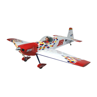
INSTRUCTION MANUAL
• 90% prebuilt
• Precovered in genuine Hangar 9
• Prefinished fiberglass cowl and wheel pants
• Designed by 8-time TOC competitor Mike McConville
Specifications:
Wingspan: .................................................................................................................. 80 in (2032 mm)
Length: ..................................................................................................................... 70
Wing Area: .................................................................................................... 1248 sq in (80.5 sq dm)
Weight (Approx.): .......................................................................................... 14 –16 lb (6.4 –7.3 kg)
Scale: ................................................................................................................................................... 27%
Recommended Engines:
Ultra Aerobatic 80" ARF
™
UltraCote
®
covering
1.80–2.18 2-Stroke
Saito
™
300 Twin 4-Stroke
Zenoah
®
G-38–G-45 Gasoline Engine
TM
1
/
in (1784 mm)
4
Advertisement
Table of Contents

Related Manuals for Hangar 9 80" CAP 232


Summary of Contents for Hangar 9 80" CAP 232
-
Page 1: Instruction Manual
Ultra Aerobatic 80" ARF INSTRUCTION MANUAL • 90% prebuilt ™ • Precovered in genuine Hangar 9 UltraCote ® covering • Prefinished fiberglass cowl and wheel pants • Designed by 8-time TOC competitor Mike McConville Specifications: Wingspan: ........................80 in (2032 mm) Length: ........................ -
Page 2: Table Of Contents
Table of Contents Introduction ............................3 Warning .............................. 3 Additional Required Equipment ......................4 Other Items Needed (not included in the kit) ..................5 Tools and Adhesives Needed (not included in the kit) ............... 5 Additional Needed Items ........................5 Contents of Kit ............................5 Section 1. -
Page 3: Introduction
Introduction Thank you for purchasing the Hangar 9 80" CAP 232. Because the size and weight create a higher degree for potential danger, an ™ added measure of care and responsibility is needed when building and flying giant scale models. If this is your first giant scale aerobatic aircraft, it’s important that you carefully follow the instructions. -
Page 4: Additional Required Equipment
Additional Required Equipment Radio Equipment with Computer Radio 1000mAh receiver battery pack or larger Servos (5) with 80 oz/in of torque minimum or equivalent Servo for throttle 18" Servo Extension (2) (JRPA099) 12" Servo Extension (2) (JRPA098) Radio Equipment (Non-Computer Radio) 1000mAh receiver battery pack or larger Servos with 80 oz/in of torque minimum (5) (JR8101, 4721, 2721, or 8411 or equivalent) -
Page 5: Other Items Needed (Not Included In The Kit)
Paper towels 2' fuel tubing Rubbing alcohol Coarse sandpaper Felt-tipped pen/pencil ™ ® Radio packing foam Hangar 9 UltraCote (HANU887) Antenna tube (used for sealing aileron/elevator hinge gap) 8-32 x 1 " cap screws (4) Contents of Kit Large Parts A. -
Page 6: Section 1: Hinging And Sealing The Ailerons
T-pin (one for each hinge) (optional procedure) Sealing iron Ruler Felt-tipped pen or pencil Step 3 photo ™ Clear Hangar 9 UltraCote ® (HANU887) Step 4. Deflect the aileron and completely saturate each hinge Hobby knife with #11 blade with thin CA glue. The aileron’s front surface should lightly con- Scissors tact the wing during this procedure. - Page 7 Step 6. Using CA remover/debonder and a paper towel, Step 9. Cut two pieces of Clear UltraCote ® (HANU887 not remove any excess CA glue that may have accumulated on the included) for sealing the ailerons to approximately 3" x 33". Fold wing or in the aileron hinge area.
- Page 8 Step 12. Mark and cut both folded coverings to an overall Step 14. Fully deflect the aileron in the up position. Place the length of 1 ". These pieces will be inserted and ironed down straight edge over the hinge line covering that you just ironed into the hinge bevel on the bottom of the ailerons.
-
Page 9: Section 2: Joining The Wing Halves
Section 2: Joining the Wing Halves Parts Needed Step 3. The correct dihedral angle for the wing is 3 degrees. Place the wing on a large flat surface with buttom of one wing Right/left wing panels panel resting on the flat surface. The wing tip should be Dihedral brace "... - Page 10 Step 6. Coat one half of the wing joiner with epoxy up to Step 8. Apply epoxy to all sides of the exposed wing joiner the line marked in Step 1. Install the epoxy coated side of the and uniformly coat both wing roots with epoxy. dihedral brace into the wing panel cavity up to the center line marked.
- Page 11 Step 10. Apply masking tape at the wing joint to hold the wing Step 11. Allow the wing center joint to completely cure then halves together securely. Place the wing on a flat surface. With remove the masking tape. the left wing panel firmly supported to lay flat on the surface, the wing tip should be propped up so it is 3 "...
-
Page 12: Section 3: Installing The Aileron Servos
Section 3: Installing the Aileron Servos Parts Needed Step 3. With the servo in place, mark the location of the servo screws used to mount the servo to the plywood servo rail inside Wing with ailerons attached the wing servo opening. Not Included with the Kit Servos with Mounting Hardware (2) (JRPS8101 or equivalent) Servo extensions recommended) (12") (2) - Page 13 Step 6. Use a piece of string with a small weight (bolt from Step 9. Repeat the procedure for the other wing half. engine mounting hardware) attached as a device to attach to one end of the servo lead extension and thread through the servo Note: If you are using a non-computer radio, it will be opening, through the wing, and out the servo lead exit.
-
Page 14: Section 4: Installing The Aileron Control Horns
Placing a wooden block under the aileron Tools and Adhesives Needed and drilling slowly will prevent these problems. If you choose to use the counter sink screws included in the Hangar 9 Hardware Ruler Package, counter sink the top of the aileron to allow the screws Drill Bit: 8/32"... - Page 15 Step 5. Mix a small amount of 30-minute epoxy and lightly Step 6. Screw the molded swivel links onto the inboard 8-32 coat the inside of the tapped holes and the 8-32 x 2" Rocket City screw until the distance from the aileron surface to the bottom of screw.
-
Page 16: Section 5: Installing The Aileron Linkages
Hangar 9 also offers a Pro-Link Wrench (HAN3558) to make adjustments easier. Step 4. Repeat the process for the other aileron linkage. -
Page 17: Section 6: Mounting The Wing To The Fuselage
Section 6: Mounting the Wing to the Fuselage Parts Needed Wing Fuselage Wing hold-down hardware Tools and Adhesives Needed Hobby knife with #11 blade 30-minute epoxy Epoxy brush Mixing stick Rubbing alcohol Felt-tipped pen or pencil Step 5. Remove the wing from the fuselage. Trim away the Pliers covering 1/8"... -
Page 18: Section 7: Installing The Tail
Section 7: Installing the Tail Parts Needed Step 3. Trial fit the horizontal stabilizer onto the rear of the fuselage. Use masking tape to hold the horizontal stabilizer in Fuselage place while making measurements. Use a ruler to check to make Wing sure the horizontal stabilizer projects the same amount from each Horizontal stabilizer with elevators... - Page 19 Step 6. Mix approximately 1 ounce of 30-minute epoxy. Re- Step 8. Mix approximately 1/2 ounce of 30-minute epoxy and install the horizontal stabilizer. Apply the epoxy to the horizontal apply to the vertical stabilizer where it contacts the fuselage and stabilizer and to the opening in the fuselage.
-
Page 20: Hinging The Horizontal Stabilizer And Elevators
Section 8: Hinging the Horizontal Stabilizer and Elevators Parts Needed Step 3. After the hinges are dry, check to be sure they are securely in place by trying to pull the elevator from the horizontal Fuselage with vertical and horizontal stabilizer attached stabilizer. -
Page 21: Section 9: Hinging The Rudder And Installing The Tail Wheel
Section 9: Hinging the Rudder and Installing the Tail Wheel Parts Needed Step 3. Hold the tail wheel assembly up to the fuselage in a position where it’s flush with the fuselage bottom. Note where the Rudder mounting bracket rests in reference to the rudder. Use a felt- Fuselage tipped pen or pencil to mark the position where the holes for the Tail Wheel Assembly (SUL861, not included) - Page 22 Step 6. Deflect the rudder back and forth, making sure the tail Step 8. Install the tail wheel. wheel turns freely with the rudder and there is no binding. This will also help work in the hinges. Note: The wheel must rotate freely with only a small amount of side play.
-
Page 23: Section 10: Installing The Radio
Section 10: Installing the Radio Parts Needed Step 3.Trial fit the rudder servo tray into the fuselage. Note there is an opening for the rudder servo and a switch. The open- 4-channel radio system with 5 servos and hardware (not included) ing for the switch faces toward the front of the aircraft. - Page 24 Step 6. Use radio packing foam (available at your local hobby Step 7. Route the antenna back through the fuselage using shop) when you install the receiver and battery pack. There is an antenna tube (not included), or route it out the side of the ample room for the receiver and battery in the forward part of the fuselage, back toward the tail.
-
Page 25: Section 11: Installing The Elevator Servos
Section 11: Installing the Elevator Servos Parts Needed Step 1B. If using a non-computer radio, install two 24" servo extensions, one on each servo. Tape and tie a knot at each con- Fuselage with horizontal stab/elevators nector to prevent inadvertent disconnection. Use a Y-connector Using a Computer Radio to connect the two servos to the receiver. - Page 26 Step 4. Use the servo mounting screws provided in your radio Step 5. Remove the standard servo arms from the elevator ser- system, and mount the servos in the fuselage. Thread the servo vos and replace with Heavy Duty (1") Arm (HAN374). Note that leads though the fusealge and connect to the receiver.
-
Page 27: Installing The Elevator Horns And Linkages
Section 12: Installing the Elevator Horns and Linkages Parts Needed Fuselage 4-40x3/8" screws (2) Rocket City 8-32 Swivel Control Horn (ROC01B) Control horns (2) 4-40 Ball Links (2) (ROC87) 4-40 Pro-Links (2) (HAN3556) Tools and Adhesives Needed Hobby knife with #11 blade Drill Bit: 5/32"... - Page 28 Step 5. Install the a nut and then screw the molded swivel link Step 7. Screw a 4-40 ball link five to six turns onto a 3" long onto the 8-32 screw until the distance from the elevator surface 4-40 pro-link. Screw the opposite end of the linkage into the to the bottom of the link is 5/8".
-
Page 29: Installing The Rudder, Control Horns, And Pull-Pull Linkages
Section 13: Installing the Rudder, Control Horns, and Pull-Pull Linkages Parts Needed Step 1. Mark the position for the rudder control horn with a felt-tipped pen or pencil. The correct locaton is 3/4" up from the Rudder bottom of the rudder and 1/4" rearward from the edge of the Fuselage rudder bevel. - Page 30 Step 7 photo Step 8. Remove the stock servo arm from the rudder servo and replace with a Hangar 9 heavy-duty servo arm. Step 5. Use a moto-tool and cut-off wheel to cut the bolt on the side with the head so that 1" of thread remains exposed, thus giving 1"...
-
Page 31: Section 14: Installing The Main Landing Gear
Section 14: Installing the Main Landing Gear Parts Needed Step 2. Trial fit the aluminum main landing gear over the holes in the fuselage. Fuselage Main landing gear Mounting hardware Tools and Adhesives Needed Hobby knife with #11 blade Phillips screwdriver Felt-tipped pen or pencil Locktite Z-42 Step 1. -
Page 32: Assembling And Mounting The Wheel Pants
Section 15: Assembling and Mounting the Wheel Pants Parts Needed Note: Notice which side of the wheel pant goes against the landing gear before making your mark. Wheel pants 1/2" Main landing gear Mounting hardware package Plywood wheel pant mounts (2) Not Included: 3"... - Page 33 Step 6. Drill the main axle hole using a 3/8" drill bit. It is Step 9. Repeat Step 9 for the other wheel pant. helpful to start with a 1/8" pilot hole first. Once the hole is drilled, trial fit the axle to the opening again. You may have to Step 10.
-
Page 34: Section 16: Installing The Engine
Section 16: Installing the Engine Parts Needed Fuselage Engine Motor mount (not included) Mounting hardware (not included) Kill switch (if using a gasoline engine) Fuel Filler (HAN115) not included Tools and Adhesives Needed Phillips screwdriver 30-minute epoxy Rubbing alcohol Epoxy brush Mixing stick Step 3. - Page 35 Installing a Glow Engine Step 2. With the engine mounted, the throttle linkage opening in the firewall can be marked using a felt-tipped pen or pencil. Step 1. The next is the mounting of a two-stroke Moki engine The throttle linkage will be installed later. Also make and drill to the CAP 232.
-
Page 36: Assembling And Installing The Fuel Tank
Section 17: Assembling and Installing the Fuel Tank Parts Needed Step 4. Wrap foam around the fuel tank to reduce vibration and mount it to the plywood fuel tank floor. Fuel Tank (not included in kit) (DUB424) Tools and Adhesives Needed Hobby knife with #11 blade Phillips screwdriver Tubing bender (optional) - Page 37 Step 6. Mix approximately 1/4 ounce of 6-minute epoxy and Step 7. Allow the epoxy to cure completely. Additional foam epoxy the fuel tank plywood floor in place. can be applied around the tank in the fuselage space behind the firewall. Note: Remove the fuel tank when drilling the hole for the throttle linkage to prevent accidental puncturing of the fuel tank.
-
Page 38: Installing The Throttle Control Linkage
Section 18: Installing the Throttle Control Linkage Parts Needed Step 2. Begin the installation of the throttle linkage by attach- ing a nylon clevis to the threaded end of a rod (10 turns). Insert Fuselage the throttle linkage through the firewall and attach the nylon Throttle Linkage (not included) clevis to the throttle control arm on the engine. -
Page 39: Section 19: Attaching The Cowling
Section 19: Attaching the Cowling Parts Needed Note: For illustration purposes, we have shown both a Zenoah ® G-45 and Moki 2.10 engine mounted in the 80" CAP Fiberglass cowl 232. If you use a different engine, it will be necessary to make 4-40 nylon screws (4) the appropriate template and mark the cowl to fit the engine Blind nuts (4) -
Page 40: Section 20: Mounting The Canopy
Section 20: Mounting the Canopy Parts Needed Step 4. Locate the instrument panel decal from the decal sheet. Cut the instrument panel out and trial fit it to the hatch area in Fuselage the front area of the cockpit. When you’re satisfied with the fit, Canopy peel away the backing and apply the instrument panel decal to Instrument pane decal... -
Page 41: Section 21: Adding Decals
Apply the decals to the cowl and rub with a soft cloth to of the vertical stabilizer and rudder as shown. work out any bubbles or wrinkles. ™ Step 3. Next, apply the Hangar 9 decal to the wheel pants. -
Page 42: Section 22: Balancing The 80" Cap 232
Section 22: Balancing the 80" CAP 232 It is essential that 80" CAP 232 be properly balanced before any generation of aerobatic maneuvers, such as waterfalls, elevators attempt is made to fly the aircraft. Don’t inadvertently neglect and harriers. However, they also make the model very sensitive. this step. -
Page 43: Ama Safety Code
AMA Safety Code 2001 Official AMA National Model Aircraft Safety Code Effective January 1, 2001 Model flying must be in accordance with this Code in order for JATO use); also those items authorized for Air Show Team AMA Liability Protection to apply. use as defined by AST Advisory Committee (document available from AMA HQ). - Page 44 © Copyright 2001, Horizon Hobby, Inc. (217) 355-9511...
Need help?
Do you have a question about the 80" CAP 232 and is the answer not in the manual?
Questions and answers