Table of Contents
Advertisement
TM
TM
WE GET PEOPLE FLYING
Specifications
Wingspan: 80-1/8"
Wing Area: 850 sq. in.
Weight (Approx.): 6.5-7.0 lbs.
Recommended Engines:
.40-.46 2-Cycle
.45-.60 4-Cycle
Raising the Standard of Quality in
Almost Ready-To-Fly Aircraft
• Ultra Covering
• Pre-finished Fiberglass Cowl
• Highest Quality Craftsmanship
• 90% Pre-Built
• IMAA-Legal 80-1/8" Wingspan
90
%
PRE-BUILT
ALMOST READY-TO-FLY
ASSEMBLY MANUAL
Advertisement
Table of Contents

Related Manuals for Hangar 9 J-3 Piper Cub


Summary of Contents for Hangar 9 J-3 Piper Cub
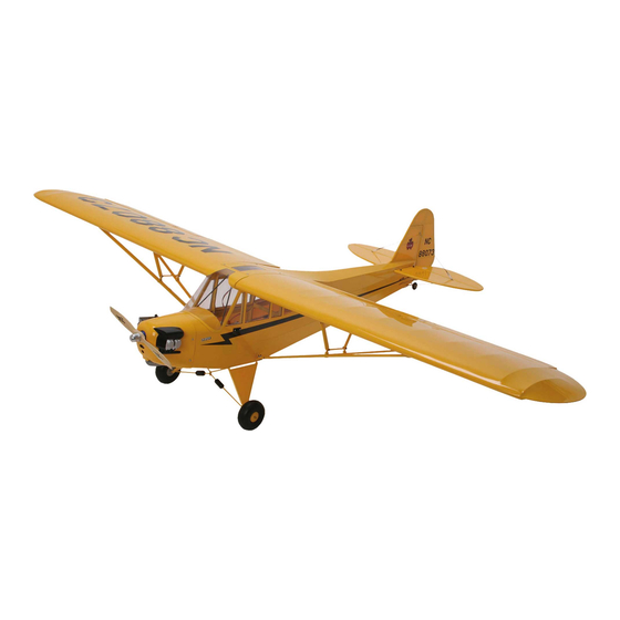
- Page 1 WE GET PEOPLE FLYING ASSEMBLY MANUAL Specifications Wingspan: 80-1/8" Wing Area: 850 sq. in. Weight (Approx.): 6.5-7.0 lbs. Recommended Engines: .40-.46 2-Cycle .45-.60 4-Cycle Raising the Standard of Quality in Almost Ready-To-Fly Aircraft • Ultra Covering • Pre-finished Fiberglass Cowl •...
-
Page 2: Table Of Contents
Section 12: Installing The Linkages Section 13: Attaching The Cowl Section 14: Installing The Windows Section 15: Scale Detailing Section 16: Balancing the J-3 Piper Cub Section 17: Control Throw Recommendation Section 18: Flying the J-3 Piper Cub Pre-Flight Check... -
Page 3: Introduction
Ultra covering. This means you can have a large (80-1/8" span), high quality scale J-3 Piper Cub, showing it to your friends at the field in 20 hours or less. Best of all, they’ll never know it’s an ARF, and chances are they’ll compliment you on your building and... -
Page 4: Additional Equipment Required
Additional Equipment Required Radio Equipment Engine Recommendations 4 Channels (minimum) .40-.46 2-Cycle Engines 5 Standard Servos .45-.55 4-Cycle Engines Standard 450-650 mAh Receiver Battery Pack Y-Harness 2 Servo Extensions Saito .50GK Thunder Tiger Pro .40 Saito .56GK Recommended JR Systems Recommended 2-Cycle Engines JR F400 FM JR XF642FM/PCM... -
Page 5: Section 1: Hinging The Aileron
CA. and the wing. 1. Carefully remove the aileron from one of the wing panels. Note the position of the hinges. The J-3 Piper Cub comes with high quality CA-type hinges, which are manufactured in the USA. -
Page 6: Section 2: Joining The Wing Halves
Section 1: Hinging The Ailerons CONTINUED 6. After both ailerons are securely hinged, firmly grasp the wing and aileron to check that the hinges are immovable. Do this by applying medium pressure, trying to separate the aileron from the wing. Section 2: Joining the Wing Halves Parts Needed Tools And Adhesives Needed... - Page 7 Section 2: Joining the Wing Halves CONTINUED 3. Next, check for the correct dihedral angle. Place the wing on a large, flat surface with one wing panel resting on the flat surface. The opposite wing tip should be exactly 2" from the surface (see illustration below).
-
Page 8: Section 3: Installing The Aileron Servos
Section 2: Joining the Wing Halves CONTINUED 9. Carefully slide the two wing halves together. Firmly press the halves together, allowing the excess epoxy to run out. Using rubbing alcohol and a paper towel, clean off the excess epoxy. There should not be any gap between the wing halves. - Page 9 Section 3: Installing the Aileron Servos CONTINUED 2. Install the grommets and eyelets on both aileron servos. 5. Using scissors, cut out the aileron cover. Also, using a Now place the servo blocks on the servo as shown and hobby knife cut out the opening where the linkage exits mark with a pencil where the servo screws attach the the aileron cover.
- Page 10 Section 3: Installing the Aileron Servos CONTINUED 8. Now mark two equidistant holes as shown on the servo 11. Using 30 minute epoxy, glue the servo blocks in place, cover where the servo blocks are to be mounted. Two then screw them into position with 4 sheet metal screws. sheet metal screws, included with the J-3 Cub, will be used to mount each block to the servo cover.
- Page 11 Section 3: Installing the Aileron Servos CONTINUED 16. Near the center section on the bottom of the wing, locate 19. Plug both aileron servo connectors into a Y-harness and the two servo lead openings and carefully cut away the feed the excess servo lead wire back into the wing. covering with a sharp hobby knife.
-
Page 12: Section 4: Installing The Aileron Linkage
Note: The 30° control horn offset provides the necessary aileron differential (more up aileron than down) to correct adverse yaw tendencies of the J-3 Piper Cub. If your radio’s system is equipped with aileron to rudder mixing, you may also want to mix approximately 25% aileron to rudder mixing to further improve the turn coordination. - Page 13 Section 4: Installing the Aileron Linkage 7. Use a 1/16" drill bit to carefully drill through the aileron at 10. Install the clevis in the outermost hole. With the aileron in the marked locations, making sure the drill is exactly the neutral position and the servo arm 30°...
-
Page 14: Section 5: Mounting The Wing
Section 4: Installing the Aileron Linkage CONTINUED 13. It is a good idea to place a piece of fuel tubing over the clevis (as shown below) as extra insurance to prevent the clevis from accidentally coming open. Adjust the length of the linkage until the aileron is exactly neutral with the trailing edge. - Page 15 Section 5: Mounting the Wing CONTINUED 3. Using a 1/4" drill bit, drill through the front face of the 5. Press the blind nuts into position below the rear wing wing using the holes in the front fuselage former as a hold down plate in the fuselage.
- Page 16 Section 5: Mounting The Wing CONTINUED 7. Fit the wing back into position on the fuselage, carefully 9. Trial fit the wing into position on the fuselage. Thread the sliding the leading edge dowel rods into the front wing hold down bolts into the wing and loosely tighten. bulkhead.
-
Page 17: Section 6: Installing The Tail
Section 6: Installing The Tail Parts Needed Tools And Adhesives Needed Instant thin CA glue Razor saw Fuselage and wing from Section 5 CA remover/debonder Horizontal stabilizer with elevators Straight edge 30 minute epoxy Pencil Vertical stabilizer with rudder Hobby knife with #11 blade Masking Tape 1. - Page 18 Section 6: Installing The Tail CONTINUED 6. Trial fit the horizontal stabilizer in place in the fuselage. With the wing installed, check the alignment of the horizontal stabilizer by measuring from a fixed point on the wing to the hinge line at the tip of the horizontal stabilizer.
- Page 19 Section 6: Installing The Tail CONTINUED 10. Remove the horizontal stabilizer and the vertical fin and 13. Apply 30 minute epoxy to the vertical fin where the carefully cut away the covering with a sharp hobby knife fuselage contacts the fin. Also apply epoxy to the base of inside the lines you marked in Step 9.
-
Page 20: Section 7: Hinging The Rudder
Section 7: Hinging The Rudder Items Needed Tools And Adhesives Needed Felt tipped pen Drill Fuselage from Section 6 Instant thin CA glue 3/32" drill bit CA remover CA remover/debonder Rudder Needle nose pliers Paper towels Rudder hinges (4) Blue Locktite 242 Hobby knife Rubbing alcohol Tail wheel assembly... - Page 21 Section 7: Hinging The Rudder CONTINUED 7. When you are satisfied with the fit, disassemble the rudder 9. Work the rudder right and left. Check for free movement and tail wheel assembly. Apply 30 minute epoxy to the and ensure that the tail wheel wire tracks accordingly. pivot bushing where it glues into the fuselage and apply epoxy into the hole in the rudder.
-
Page 22: Section 8: Installing The Engine
Measuring device 1/8" drill bit Epoxy brush Note: The Hangar 9 J-3 Piper Cub is designed for .40-.46 size 3. Mix approximately 1/2 ounce of 30 minute epoxy. Using 2-cycle or .45-.60 size 4-cycle engines. For the ultimate in scale... - Page 23 Section 8: Installing The Engine CONTINUED 5. Rest the fuselage on its side with the right side of the 8. Remove the engine and mount plates. Now drill four 1/8" fuselage facing up. Place the motor mount plates on the diameter holes at the points on the engine mounting motor mount as shown in the picture below.
- Page 24 Section 8: Installing The Engine CONTINUED 11. Using a pencil, mark the engine mounting plate where 13. Now install the engine using the four screws, eight the four holes are to be drilled. (Mark through the engine washers and 4 locknuts. Note: On some engines it may mount flanges.) be necessary to remove a small section of engine mount side rail to allow clearance for the needle valve.
-
Page 25: Section 9: Landing Gear Assembly And Installation
Section 9: Landing Gear Assembly and Installation CONTINUED the landing gear, mark the mounting hole locations through the landing gear onto the fuselage and remove the gear from the fuselage. 3. Turn the fuselage upside down. Use a ruler to measure rearward approximately 5-1/4 "... -
Page 26: Section 10: Assembling And Installing The Fuel Tank
Section 10: Assembling and Installing the Fuel Tank Parts Needed Tools Needed Brass Clunk (fuel pickup) Plastic cups (2) Hobby Knife Copper tube, long (vent) Rubber stopper Small Phillips Screwdriver Copper tube, short (pickup) 3mm screw and 3mm Fuel tubing, small locknut Fuel tank 1. - Page 27 Section 10: Assembling and Installing the Fuel Tank CONTINUED 6. Install the open tube end of the clunk and tubing 9. Insert a 3mm screw into the center hole of the stopper assembly on the short copper tubing. and tighten. 7.
-
Page 28: Section 11: Installing The Radio
Section 11: Installing the Radio Parts Needed Tools Needed 4-channel radio system with Drill Radio packing foam Hobby Knife 3 servos and hardware (not included) 1/16" drill bit Pencil (not included) Antenna tube (optional, Small Phillips screwdriver Fuselage not included) Top off with a final solid layer of foam that holds 1. -
Page 29: Section 12: Installing The Linkages
Section 11: Installing The Radio CONTINUED 5. The switch can be installed in the left side of the fuselage 6. Hook up the servos and switch harness to the receiver and (typical installation). Or a cut-out is provided in the radio the battery pack as per the instructions included with your tray, allowing you to mount the switch internally and radio system. - Page 30 Section 12: Installing The Linkages CONTINUED 3. Attach the elevator control horn using the hardware 6. Center the control horn over the mark you just made and provided (two screws and back plate) and fasten in place using a pencil, mark the mounting hole locations through using a Phillips screwdriver.
- Page 31 Section 12: Installing The Linkages CONTINUED 10. Drill a 1/16" hole through the balsa dowel at the four 13. Locate the three threaded rods and two unthreaded rods. marked positions as shown. Cut 1/4" off one of the threaded rods on the unthreaded end.
- Page 32 Section 12: Installing The Linkages CONTINUED 16. Saturate the balsa with thick CA glue where the threaded 19. Repeat this process to complete the other pushrod. Note rods contact the balsa pushrod. that only one threaded rod is necessary. 20. Carefully cut away the covering at the tail of the fuselage 17.
- Page 33 Section 12: Installing The Linkages CONTINUED 22. Insert the rudder pushrod into the fuselage, threaded end 25. Insert the Z-bend into the servo arm as shown. It may be first. The threaded rod exits the fuselage at the lower left necessary to enlarge the holes in the servo arm slightly to opening in the fuselage.
-
Page 34: Section 13: Attaching The Cowl
Section 13: Attaching The Cowl Parts Needed Tools And Adhesives Needed Moto-Tool with sanding 1/16" drill bit Fiberglass cowl drum Masking tape Sheet metal screws (4) Small Phillips screwdriver Felt tipped pen Fuselage Drill Ruler Engine template (for Saito .50 engines only) Fueling valve (optional) Note: If you are using another type of engine, it will be 1. -
Page 35: Section 14: Installing The Windows
Section 15: Scale Detailing Included in the kit are several items to enhance the scale appearance of your J-3 Piper Cub. These include wing struts, shock absorbing landing gear detail, wheel inserts, vacuum- formed engine and decals. - Page 36 Section 15: Scale Detailing CONTINUED 1. A block of hardwood is built into the wing and is used as the attachment point for the rear wing strut mounts. The Landing Gear front wing strut mounts are screwed into the spar. Locking Screw Clevises are used on this end of the struts for easy installation/removal.
- Page 37 Section 15: Scale Detailing CONTINUED 5. A vacuum-formed scale engine is included. It can be trimmed and painted with most hobby enamel type paints. Before painting, be sure to thoroughly wash the scale engine with soap and water to remove any mold release. When the paint is dry, glue a small block of balsa wood inside the scale engine.
-
Page 38: Section 16: Balancing The J-3 Piper Cub
Section 15: Scale Detailing CONTINUED Additional Scale Detailing Section 16: Balancing the J-3 Piper Cub An important part of preparing any aircraft for flight is properly balancing the model. Don’t inadvertently forget this crucial step. The recommended C.G. (Center of Gravity) location for the first flights with the J-3 Cub is 3-1/4"... -
Page 39: Section 17: Control Throw Recommendation
Section 18: Flying the J-3 Piper Cub If you can successfully solo a trainer-type airplane, you’ll feel right at home with the J-3 Piper Cub. Its generous 850 sq. in. wing area, light wing loading and thick flat bottom airfoil offer excellent, nearly stall-proof slow speed stability. -
Page 40: Pre-Flight Check
Pre-Flight Check 1. Check that all control functions move in the correct direction. If not, use the respective reversing switch to correct the direction. CARBURETOR ELEVATOR 1/16” THROTTLE ELEVATOR RUDDER AILERON AILERON RUDDER 2. Check that each clevis is securely snapped into position. 3. -
Page 41: Pre-Flight At The Field
Pre-Flight at the Field Range Test Your Radio 1. Before each flying session be sure to range check your radio. This is accomplished by turning on your transmitter with the antenna collapsed. Turn on the radio in your airplane. With your airplane on the ground, you should be able to walk 30 paces away from your airplane and still have complete control of all functions. -
Page 42: Ama Safety Code
AMA Safety Code 1994 Official AMA National Model Aircraft Safety Code I will not operate models with pyrotechnics (any device that explodes, burns, or propels a projectile of any kind) including, but not limited to, Effective January 1, 1994 rockets, explosive bombs dropped from models, smoke bombs, all Model flying must be in accordance with this Code in explosive gases (such as hydrogen-filled balloons), ground mounted order for AMA liability protection to apply... -
Page 43: Cowl Template (For Saito .50 Or .56)
COWL TEMPLATE For Saito .50 and .56 Cowl Template This is the minimum size of cut-out required — For Saito .50 enlargement may be necessary to meet your specific needs. Cut out for engine Line up with edges of cowl... - Page 44 HAN1501...
Need help?
Do you have a question about the J-3 Piper Cub and is the answer not in the manual?
Questions and answers