Table of Contents
Advertisement
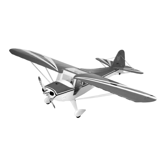
• 90% prebuilt
• Giant scale legal
• Precovered with genuine UltraCote
• Featuring one-of-a-kind scale trim scheme
• Prefinished fiberglass cowl
• Gas or glow option
Specifications
Wingspan: . . . . . . . . . . . . . . . . . . . . . . . 85
Length: . . . . . . . . . . . . . . . . . . . . . . . . . . . 67 in . . . . . . . . . 1702 mm
Wing Area: . . . . . . . . . . . . . . . . . . . . 1315 sq in . . . . . . . . . 84.4 dm sq
Flight Weight: . . . . . . . . . . . . . . . . . . 13–15 lb . . . . . . 5.9–6.8 kg
Recommended Engines: . . . . . . . . . . . . . . . . . . . . 1.08 - 1.48 2-Stroke
WE GET PEOPLE FLYING
INSTRUCTION MANUAL
®
1
/
in . . . . . . . . . 2172 mm
2
1.20 - 1.82 4-Stroke
Zenoah .23 Gas
TM
TM
Advertisement
Table of Contents

Related Manuals for Hangar 9 Clipped-wing Taylorcraft


Summary of Contents for Hangar 9 Clipped-wing Taylorcraft
-
Page 1: Instruction Manual
WE GET PEOPLE FLYING INSTRUCTION MANUAL • 90% prebuilt • Giant scale legal • Precovered with genuine UltraCote ® • Featuring one-of-a-kind scale trim scheme • Prefinished fiberglass cowl • Gas or glow option Specifications Wingspan: ..... . . 85 in . -
Page 2: Table Of Contents
Section 21: Balancing the Clipped-Wing Taylorcraft ........ -
Page 3: Introduction
The Clipped-Wing Taylorcraft used in the instructions for this kit was a production model just like yours. This is a "stand-off scale" model, however the experienced modeler will find that this kit has the basic components that will allow for numerous variations. If you decide to make scale variations, we would be very interested in learning about your effort. -
Page 4: Additional Required Equipment
Additional Required Equipment Radio Equipment Systems 4 channels (minimum) 5 servos (JRPS8101 servos recommended) Standard 600-1000mAh Receiver Battery Pack Y-harness (if a non-computer radio is used) Recommended JR Systems JR XF652 JR XP783 JR XP8103 PCM10X JR 8103 Engines 1.08 - 1.48 2-Cycle Engines 1.20 - 1.82 4-Cycle Engines Zenoah G23 Gas Engine Recommended... - Page 5 Other Items Needed (not included in the kit) Aileron Extension (2) (JRPA098, 12" Gold) Propeller Fuel filter Foam for cushioning tank Fuel tubing Fuel Filler (HAN119) Shut-Off Switch for gasoline engine (kill-switch) (ZEN2000) Radio packing foam Tools and Adhesives Needed (not included in the kit) Adhesives Thin CA (cyanoacrylate) glue 6-minute epoxy...
-
Page 6: Contents Of Kit
Contents of Kit Replacement Parts Large Parts Wheel Pants (HAN1856) Fuselage (HAN1852) Cowl (HAN1855) Wing Set (HAN1851) True Red UltraCote ® (HANU866) Tail Set (HAN1853) White UltraCote (HANU870) Decal Set (HAN1859) Black UltraCote (HANU874) Main Landing Gear w/Mounting Hardware (HAN1857) Red/White 2"... -
Page 7: Section 1: Hinging The Ailerons
Section 1: Hinging the Ailerons Parts Needed Tools and Adhesives Needed Right wing panel with aileron and hinges Instant thin CA glue Paper towels T-pins (one for each hinge) Left wing panel with aileron and hinges CA remover/debonder Note: The control surfaces, including the ailerons, Step 4. - Page 8 Section 1: Hinging the Ailerons CONTINUED Step 6. Using CA remover/debonder and a paper towel, Step 8. After both ailerons are securely hinged, firmly grasp remove any excess CA glue that may have accumulated on the the wing and aileron and check that the hinges are securely wing or in the aileron hinge area.
-
Page 9: Section 2: Joining The Wing Halves
Section 2: Joining the Wing Halves Parts Needed Tools and Adhesives Needed Right/left wing panels 30-minute epoxy Wax paper Wing joiner Epoxy brush Ruler Masking tape Pencil Hobby knife Medium sandpaper Rubbing alcohol Mixing stick Paper towels Step 1. Locate the wing joiner. Using the ruler, determine the Step 4. - Page 10 Section 2: Joining the Wing Halves CONTINUED Step 6. Place one wing half right-side up on a flat work Step 8. Apply a generous amount of epoxy into the wing brace surface. Use a scrap piece of wood or an epoxy brush and smear cavity of the other wing panel.
- Page 11 Section 2: Joining the Wing Halves CONTINUED Step 10. Carefully slide the two wing halves together and Step 11. Apply masking tape at the wing joint to hold the wing firmly press them together, allowing the excess epoxy to run out. halves together securely.
-
Page 12: Section 3: Installing The Aileron Servos
Section 3: Installing the Aileron Servos Parts Needed Tools and Adhesives Needed Assembled wing Hobby knife Standard size servos (2) Phillips screwdriver (medium) Servo extensions (12") (JRPA114) (2) Drill Nylon wire (36") Drill Bit: 1/16" Y-harness (if using a non-computer radio) Masking tape Pencil Needle-nose pliers... - Page 13 Section 3: Installing the Aileron Servos CONTINUED Step 5. Using a 1/16" drill bit, drill the servo screw locations Step 8. Once you have the string threaded through the wing, tie marked in Step 4. it to the servo lead extension connector. Carefully thread the servo wire extension through the wing.
-
Page 14: Section 4: Installing The Aileron Linkages
Section 4: Installing the Aileron Linkages Parts Needed Tools and Adhesives Needed Wing assembly from Section 3 Drill 4-40 Aileron linkages (x 3 ") (2) (threaded on both ends) Drill Bit: 1/16" Control horns (2) Phillips screwdriver (small) Screws (4) Felt-tipped pen Clevis (4) Masking tape... - Page 15 Section 4: Installing the Aileron Linkages CONTINUED Step 5. Repeat Steps 2–4 for the other aileron control horn. Step 8. Do the same for the other aileron linkage. Step 6. Locate the two threaded aileron wire linkages Step 9. Attach the linkages onto their respective aileron control (4-40 x 3 ").
-
Page 16: Section 5: Mounting The Wing To The Fuselage
Section 5: Mounting the Wing to the Fuselage Parts Needed Tools and Adhesives Needed Complete wing assembly CA glue (thin) Fuselage Drill Wing dowel rods (2) Drill Bit: 1/8", 1/4" Fuselage wing hold-down screws/washers (2) Phillips screwdriver (medium) Blind nuts (2 ) Round file (small) Wing center plate Hobby knife... - Page 17 Section 5: Mounting the Wing to the Fuselage CONTINUED Step 5. Place the wing on the fuselage. The leading edge Step 8. With the wing secured, drill the dowel holes into the should be centered on the front windshield former opening. shaped leading edge material you glued to the wing leading edge in Step 2, using a 1/4"...
- Page 18 Section 5: Mounting the Wing to the Fuselage CONTINUED Step 11. Trim away the film covering the wing bolt holes in the Step 14. Check the wing alignment at the rear with reference wing bolt plate. Next, trim the covering where the wing bolt plate to the centerline mark.
- Page 19 Section 5: Mounting the Wing to the Fuselage CONTINUED Step 16. Press the blind nuts into position below the rear wing Step 17. A small drop of CA glue will help hold the blind nuts hold-down block in the rear portion of the fuselage wing area. in place.
-
Page 20: Section 6: Installing The Tail (Vertical And Horizontal Stabilizer)
Section 6: Installing the Tail (Vertical and Horizontal Stabilizer) Parts Needed Tools and Adhesives Needed Felt-tipped pen Fuselage Thin CA glue Masking tape Wing CA remover/debonder Rubbing alcohol Horizontal stabilizer with elevators 30-minute epoxy Paper towels Vertical stabilizer with rudder Epoxy brush 90-degree triangle Hobby knife with #11 blade... - Page 21 Section 6: Installing the Tail (Vertical and Horizontal Stabilizer) CONTINUED Step 6. With the fuselage resting on a flat surface, align the Step 9. Trial fit the vertical stabilizer in position on the horizontal stabilizer by measuring from fixed points on the wing fuselage, after removing the rudder and hinges.
- Page 22 Section 6: Installing the Tail (Vertical and Horizontal Stabilizer) CONTINUED Step 12. When you’re satisfied with the alignment, carefully Step 15. Check the alignment of the horizontal stabilizer by mark the position of the vertical stabilizer where it meets the referring to the marks made previously, and measuring the wing fuselage/horizontal stabilizer with a pencil.
-
Page 23: Section 7: Hinging The Horizontal Stabilizer And Elevator
Section 7: Hinging the Horizontal Stabilizer and Elevators Parts Needed Tools and Adhesives Needed Fuselage with horizontal and vertical stabilizers mounted Thin CA glue Elevators (2) CA debonder Paper towels T-pins Step 1. Locate the two elevator halves. Trial fit each into Step 3. -
Page 24: Section 8: Hinging The Rudder And Installing The Tail Wheel
Section 8: Hinging the Rudder and Installing the Tail Wheel Parts Needed Tools and Adhesives Needed Rudder Thin CA glue Drill Drill Bits: 1/16", 3/32" Fuselage CA remover/debonder Tail wheel assembly Blue Locktite Z-42 Felt-tipped pen 30-minute epoxy Paper towels Needle-nose pliers Rubbing alcohol Toothpicks (optional) - Page 25 Section 8: Hinging the Rudder and Installing the Tail Wheel CONTINUED Step 6. Trial fit the tail wheel assembly and rudder in place. Step 9. With the rudder and tail wheel assembly installed, Deflect the rudder, making sure the tail wheel turns freely with apply thin CA glue to the rudder hinges on both sides, using the rudder.
-
Page 26: Section 9: Installing The Control Horns
Section 9: Installing the Control Horns Parts Needed Tools and Adhesives Needed Standard control horns (4) Phillips screwdriver Plastic plates (2) Drill Screws (6) Drill Bit: 1/16" Nuts (2) Ruler Fuselage Felt-tipped pen Rudder Masking tape Elevators (2) Step 1. Locate the four standard control horns, two plastic Step 3. - Page 27 Section 9: Installing the Control Horns CONTINUED Step 5. Using a 1/16" drill bit, drill two holes through the Step 8. Install the rudder control horns on the left and right elevator so the control horn can be mounted. side of the rudder. Measure up 1 "...
- Page 28 Section 9: Installing the Control Horns CONTINUED Step 11. Drill the holes with a 1/16" drill bit. Install a rudder control horn on both sides of the rudder with two screws and two nuts. Again, make sure the control horns are centered over the hinge line.
-
Page 29: Section 10: Installing The Main Landing Gear And Wheel Pants
Section 10: Installing the Main Landing Gear and Wheel Pants Parts Needed Tools and Adhesives Needed Main landing gear (2) 30-minute epoxy Phillips screwdriver (medium) Round file Main landing gear straps (4) Epoxy brush Self-tapping screws (8 Mixing Stick Paper towels Wheel pants (2) Pencil Sandpaper... - Page 30 Section 10: Installing the Main Landing Gear and Wheel Pants CONTINUED Installation of Wheel Pants Step 9. Locate the two plywood square pieces (1 " square) included with the wheel pants. These will be epoxied inside the Step 7. Locate the two wheel pants and associated hardware, wheel pants as a brace or reinforcement for mounting the wheel including the two 1 "...
- Page 31 Section 10: Installing the Main Landing Gear and Wheel Pants CONTINUED Step 13. Use caution that you do not split the wood. Step 18. Mount the wheel pant to the axle and screw in the 4-40 bolt into the small hole above the axle, so that it screws into the blind nut.
-
Page 32: Section 11: Installing The Engine (Glow Option)
Section 11: Installing the Engine (Glow) Parts Needed Tools and Adhesives Needed Fuselage Phillips screwdriver Metal engine mounts (2) Allen wrench Mounting hardware 30-minute epoxy Engine Epoxy brush Rubbing alcohol Paper towels Note: When any engine is properly mounted the distance Step 3. - Page 33 Section 11: Installing the Engine (Glow) CONTINUED Step 5. Trial fit your engine on the motor mount. Once the proper width has been confirmed, tighten the screws on the metal motor mounts. You can remove your engine at this point while completing the following sections.
-
Page 34: Section 12: Installing The Engine (Gas Option)
Section 12: Installing the Engine (Gas) Parts Needed Tools and Adhesives Needed Fuselage Phillips screwdriver Dowel standoffs (4 round wood mounts) Allen wrench Mounting hardware Ball driver 4-4 mm x 25 mm flathead screws 30-minute epoxy 4-4 m x 30 mm machine screws Rubbing alcohol 4-4 mm nuts, 4-4 mm washers Paper towels... -
Page 35: Section 13: Assembling And Installing The Fuel Tank (Glow/Gas)
Section 13: Assembling and Installing the Fuel Tank (Glow/Gas) Parts Needed Tools and Adhesives Needed Parts Needed Tools and Adhesives Needed Brass tube, long (vent) Hobby knife Brass tube, long (fuel) Phillips screwdriver (medium) Clunk (fuel pickup) Fuel tubing, small (glow) Fuel tank Plastic cap (2) Rubber stopper (glow and gas) - Page 36 Section 13: Assembling and Installing the Fuel Tank (Glow/Gas) CONTINUED Step 7. Locate the fuel tubing. This tubing will be used for the Step 10. Carefully insert the assembly into the fuel tank. Note fuel pickup inside the fuel tank. Insert the clunk into one end of the position of the vent tube.
-
Page 37: Section 14: Installing The Radio
Section 14: Installing the Radio Parts Needed Tools and Adhesives Needed Parts Needed Tools and Adhesives Needed 4-channel radio system with 5 servos Drill Fuselage Drill Bit: 1/16" Radio packing foam (not included) Phillips screwdriver (small) Hardwood pieces (2) 1" square 1/16" thick Hobby knife with #11 blade Felt-tipped pen or pencil 6-minute epoxy... - Page 38 Section 14: Installing the Radio CONTINUED Step 6. Use radio packing foam (available at your local hobby Step 7. Route the antenna back through the fuselage using an shop) when you install the receiver and battery pack. There is antenna tube (not included), or route it outside the fuselage back ample room for the battery pack in the forward part of the to the vertical fin.
-
Page 39: Section 15: Installing The Control Linkages
Since the Clipped-Wing Taylorcraft uses a split elevator, you will construct a Y-pushrod that has two threaded rods on one end of the wooden pushrod for the two elevators, and one shorter threaded rod to connect to the servo arm. - Page 40 Section 15: Installing the Control Linkages CONTINUED Step 5. Drill a 1/8" hole at this mark. This end of the hardwood Step 9. Once you're satisfied with the fit, mix a small amount of dowel will be used as the end for the split elevators. Two of the 6-minute epoxy and apply it to the holes and areas the rods will 12"...
- Page 41 Section 15: Installing the Control Linkages CONTINUED Step 12. If the elevator servo has not been electrically Step 19. The rudder pull-pull type of linkage is made up of centered, now is the time to do so. Refer to Section 14, Step 9. music wire (.020), four threaded couplers, two clevis, screws, and hex nuts.
- Page 42 Section 15: Installing the Control Linkages CONTINUED Step 22. Trial fit one of the linkages to the servo arm of the Step 24. Insert the throttle control rod through the firewall rudder servo, compensating for the fact there will be a threaded unconnected end first.
- Page 43 Section 15: Installing the Control Linkages CONTINUED Step 26. The Z-bend is attached to the servo arm in the second Step 28. Double-check the alignment of the elevator, rudder hole from the end of the arm. Minor adjustments to the carburetor and throttle linkages.
-
Page 44: Section 16: Attaching The Cowling
Section 16: Attaching the Cowling Parts Needed Parts Needed Tools and Adhesives Needed Tools and Adhesives Needed Fiberglass cowling Drill Sanding stick Machine screws (4) Drill Bit: 1/16" Ruler Felt-tipped pen Washers (4) Masking tape Grommets (4) Moto-tool with sanding drum Phillips screwdriver Carbide cutter Step 1. - Page 45 Section 16: Attaching the Cowling CONTINUED Step 6. Locate the cowl hold down screw locations. The use of Step 8. Epoxy the cooling shroud (scoop) to the top of the cowl. a paper template will ease location of screw holes in cowl. Step 7.
-
Page 46: Section 17: Attaching The Windshield, Side Windows, And Overhead Window
Section 17: Attaching the Windshield, Side Windows, and Overhead Window Parts Needed Tools and Adhesives Needed Fuselage Phillips screwdriver Windshield, side windows (7 pcs) Scissors Wing skylight window (1 pc) Canopy Glue (Pacer Formula 560) Masking tape Small self-tapping screws (4) Trim film/tape Step 1. - Page 47 Section 17: Attaching the Windshield, Side Windows, and Overhead Window CONTINUED Step 6. After the windshield is firmly in place, apply trim film to Step 8. Use a 1/16" drill bit to drill holes in the clear overhead the frame outlines on the windshield for a more finished look. window.
-
Page 48: Section 18: Assembling And Installing The Wing Struts/Tail Braces
Section 18: Assembling and Installing the Wing Struts/Tail Braces Parts Needed Parts Needed Tools and Adhesives Needed Tools and Adhesives Needed Wing Threadlock Fuselage Phillips screwdriver Precovered right/left wing struts Pencil or felt-tipped pen Prebent music wire Aluminum tail brace pieces (6) (54 at 12 ") Wing strut and tail brace hardware (22 at 11 ") - Page 49 Section 18: Assembling and Installing the Wing Struts/Tail Braces CONTINUED Tail Braces Step 7. Check the marks you made to make sure the tail brace is aligned properly, as shown below. Step 5. Locate the tail brace pieces (6) and mounting hardware. Step 8.
-
Page 50: Section 19: Application Of Decals And Scale Detailing
Section 19: Application of Decals and Scale Detailing Parts Needed Tools and Adhesives Needed Fuselage Decals Scissors Wing Pilot (optional) Ruler Note: Refer to the box as reference for decal placement. (Step 4 photo) Placement of Decals: Step 1. Locate the decal sheet provided in the kit. Step 2. -
Page 51: Section 20: Control Throw Recommendations
Caution: Do not inadvertently neglect this step!! The recommended C.G. (center of gravity) location for the first flights with the Clipped-Wing Taylorcraft is 4 " inches from the leading edge of the wing. -
Page 52: Preflight At The Field
Preflight at the Field Range Test Your Radio Adjusting Your Radio Step 1. Before each flying session, range check your radio. Step 1. Completely read the instructions included with your This is accomplished by turning on your transmitter with the engine and follow the recommended break-in procedure. -
Page 53: Ama Safety Code
AMA National Model Aircraft Safety Code Effective January 1, 2001 Model flying must be in accordance with this code in order for 9. I will not operate models with pyrotechnics (any device that AMA Liability Protection to apply. explodes, burns, or propels a projectile of any kind) including, but not limited to, rockets, explosive bombs dropped from General models, smoke bombs, all explosive gases (such as hydrogen-... -
Page 54: Ama National Model Aircraft Safety Code
AMA National Model Aircraft Safety Code Effective January 1, 2001 ORGANIZED RC RACING EVENT B. I will not fly my model aircraft in any organized racing event which does not comply with paragraph A above or which allows A. In every organized racing event in which contestants, callers, models over 20 pounds unless that competition event is AMA and officials are on the course: sanctioned. - Page 55 Notes:...
- Page 56 ©2001 Horizon Hobby, Inc. 4105 Fieldstone Road Champaign, IL 61822 www.horizonhobby.com HAN1850.46...
Need help?
Do you have a question about the Clipped-wing Taylorcraft and is the answer not in the manual?
Questions and answers