Table of Contents
Advertisement
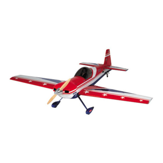
INSTRUCTION MANUAL
• 90% pre-built
• Highest quality Du-Bro and Sullivan hardware included
• Pre-covered in genuine UltraCote
• Pre-finished fiberglass cowl and wheel pants
Specifications
Wingspan:
. . . . . . . . . . . . . . . . . . . . . . . . . . . . . . . . . . . . . .
Length:
. . . . . . . . . . . . . . . . . . . . . . . . . . . . . . . . . . . . . . .
Wing Area:
. . . . . . . . . . . . . . . . . . . . . . . . . . . .
Weight (Approx.):
. . . . . . . . . . . . . . . . . . .
Recommended Engines: 1.08 –1.20 2-Stroke
1.20 –1.50 4-Stroke
WE GET PEOPLE FLYING
full scale trim scheme
''
73
''
67
1
/
4
1031 sq. in.
11–12 lbs.
TM
TM
®
featuring Matt Chapman's
90
%
PRE-BUILT
ALMOST READY-TO-FLY
Advertisement
Table of Contents

Related Manuals for Hangar 9 CAP 232


Summary of Contents for Hangar 9 CAP 232
-
Page 1: Instruction Manual
WE GET PEOPLE FLYING INSTRUCTION MANUAL • 90% pre-built • Highest quality Du-Bro and Sullivan hardware included ® • Pre-covered in genuine UltraCote featuring Matt Chapman’s full scale trim scheme • Pre-finished fiberglass cowl and wheel pants Specifications ′′ Wingspan: . -
Page 2: Table Of Contents
Table of Contents Introduction Warning Additional Equipment Required Tools and Supplies Required Contents of Kit Section 1: Hinging the Ailerons Section 2: Joining the Wing Halves Section 3: Installing the Aileron Servos Section 4: Installing the Aileron Linkages Section 5: Mounting the Wing to the Fuselage Section 6: Installing the Tail (Vertical and Horizontal Stabilizer) Section 7: Hinging the Horizontal Stabilizer and Elevator Section 8: Hinging the Rudder and Installing the Tail Wheel... -
Page 3: Introduction
Introduction Congratulations on your purchase of one of the finest ARFs to be produced! The Hangar 9 CAP 232 is a high-performance aircraft best suited for the more experienced flyer and modeler. Although this is an ARF (Almost-Ready-to-Fly) kit, it does have some construction features that can be challenging for a new modeler. -
Page 4: Tools And Supplies Required
Tools and Supplies Required Adhesives Thin CA (cyanoacrylate) glue Thick CA (cyanoacrylate) glue 6-minute epoxy 12-minute epoxy 30-minute epoxy Blue Locktite 242 Canopy glue (R/C 56) Silver solder (Stay Brite) Tools Drill Drill bits: 1/16′′, 5/32′′, 1/4′′, 1/8′′ Soldering iron Small Phillips screwdriver Medium Phillips screwdriver Z-bend pliers... -
Page 5: Contents Of Kit
Contents of Kit Large Parts A. Fuselage E. Horizontal stabilizer with elevators B. Left wing half with aileron F. Cowl C. Right wing half with aileron G. Wheel pants (2) D. Vertical stabilizer with rudder Other Parts 1. Pushrod & accessories 6. -
Page 6: Section 1: Hinging The Ailerons
Section 1. Hinging the Ailerons Parts Needed Tools and Adhesives Needed • Right wing panel with aileron and hinges • Instant thin CA glue • Left wing panel with aileron and hinges • CA remover/debonder • Paper towels • T-pin (one for each hinge) Note: The control surfaces, including the ailerons, elevators Step 3. - Page 7 Section 1. Hinging the Ailerons CONTINUED Step 5. Turn the wing panel over and deflect the aileron in the Note: Work the aileron up and down several times to “work opposite direction and from the opposite side. Apply thin CA in”...
-
Page 8: Section 2: Joining The Wing Halves
Section 2: Joining the Wing Halves Parts Needed Tools and Adhesives Needed • Right/left wing panels • 30-minute epoxy • Dihedral brace • 6-minute epoxy • Plywood wing dowel plate • Epoxy brush • Wooden dowels • Masking tape • Wing bolt plates •... - Page 9 Section 2: Joining the Wing Halves CONTINUED Step 5. Mix up approximately 1 ounce of 30-minute epoxy. Step 8. Apply a generous amount of epoxy into the wing brace cavity of the other wing panel. Note: It is extremely important to use plenty of epoxy when joining the wing halves.
- Page 10 Section 2: Joining the Wing Halves CONTINUED Step 10. Carefully slide the two wing halves together and firmly Step 12. Allow the wing center joint to completely cure, then press them together, allowing the excess epoxy to run out. There remove the masking tape.
- Page 11 Section 2: Joining the Wing Halves CONTINUED Step 15. After the wing dowels and plywood wing dowel plate Step 16. Mix up 1 ounce of 6-minute epoxy and epoxy the wing have dried, you can mount the two white covered wing bolt bolt plates to the bottom of the wing.
-
Page 12: Section 3: Installing The Aileron Servos
Section 3: Installing the Aileron Servos Parts Needed Tools and Adhesives Needed • Left/right wing halves • Hobby knife • Standard size servos (2) • Phillips screwdriver (medium) • Servo extension(s) — (12′′ recommended) (2) • Drill • Music wire (36′′) •... - Page 13 Section 3: Installing the Aileron Servos CONTINUED Step 5. Before mounting the servo, it would be wise to run the Step 7. Once you have the music wire threaded through the servo lead and extension through the wing and out the opening wing, make a small hook on one end and tape it to one end of the provided near the wing center.
-
Page 14: Section 4: Installing The Aileron Linkages
Section 4: Installing the Aileron Linkage Parts Needed Tools and Adhesives Needed • Wing assembly from Section 2 • Medium Phillips screwdriver • Left control horn • Drill • Right (reversed) control horn • Drill bits: 1/16′′, 3/32′′ • Plastic plate (2) •... - Page 15 Section 4: Installing the Aileron Linkage CONTINUED Step 5. Using a 3/32′′ drill bit, drill the screw holes for Step 6. Attach the control horn to the aileron using four screws mounting the control horn. Since the aileron balsa is soft, we and the plastic plate.
-
Page 16: Section 5: Mounting The Wing To The Fuselage
Section 5: Mounting the Wing to the Fuselage Parts Needed Tools and Adhesives Needed • Pliers • Wing • 30-minute epoxy • Ruler • Fuselage • 12-minute epoxy • Plywood wing dowel supports (2) • Epoxy brush • Drill • 1/4 ′′ drill bit •... - Page 17 Section 5: Mounting the Wing to the Fuselage CONTINUED Step 7. Press the blind nuts into position below the rear wing Step 8. Thread the wing hold-down bolts into the bottom side of hold-down block in the rear portion of the fuselage wing area. the blind nuts so the ends of the bolts extend 1/8′′...
- Page 18 Section 5: Mounting the Wing to the Fuselage CONTINUED Step 11. Once you’re satisfied with the alignment, press down Step 12. Using a 1/4′′ drill bit, drill the exact center of the wing slightly but firmly on the rear section of the wing. The protruding indentations on the top of the wing, through the wing and wing wing bolts will make an indentation in the top wing covering.
-
Page 19: Section 6: Installing The Tail (Vertical And Horizontal Stabilizer)
Section 6: Installing the Tail Parts Needed Tools and Adhesives Needed • Rubbing alcohol • Fuselage • Instant thin CA glue • Paper towels • Wing • CA remover/debonder • 90-degree triangle • Horizontal stabilizer with elevators • 30-minute epoxy •... - Page 20 Section 6: Installing the Tail CONTINUED Step 5. Trial fit the vertical fin in position. Make sure the fin is inserted completely. Some slight trimming to the bottom of the fin may be required. Carefully check the fin to be sure it’s aligned Step 7.
- Page 21 Section 6: Installing the Tail CONTINUED Step 9. Mix up approximately 2 ounces of 30-minute epoxy. Step 11. Precisely align the horizontal stabilizer and the vertical Slide the horizontal stabilizer into the opening of the fuselage. fin as before, using masking tape to hold the components in Use an epoxy brush to apply epoxy to the horizontal stabilizer.
-
Page 22: Section 7: Hinging The Horizontal Stabilizer And Elevator
Section 7: Hinging the Horizontal Stabilizer and Elevator Parts Needed Tools and Adhesives Needed • Fuselage • Thin CA glue • Elevators (2) • CA debonder • Paper towels • T-pins Step 1. Locate the two elevator halves. Trial fit each into their Step 3. -
Page 23: Section 8: Hinging The Rudder And Installing The Tail Wheel
Section 8: Hinging the Rudder and Installing the Tail Wheel Parts Needed Tools and Adhesives Needed • Rudder • Instant thin CA glue • Fuselage • CA remover/debonder • Tail wheel assembly • Blue Locktite 242 • 30-minute epoxy • Drill •... -
Page 24: Installing The Tail Wheel
Section 8: Hinging the Rudder and Installing the Tail Wheel CONTINUED Step 5. Using a hobby knife, cut a slot or groove into the back Step 8. With the rudder aligned (up and down), apply thin CA of the fuselage vertical stabilizer as marked to accept the tail glue to the rudder hinges on both sides, using the same wheel pivot bushing. -
Page 25: Section 9: Installing The Control Horns
Section 9: Installing the Control Horns Parts Needed Tools and Adhesives Needed • Standard/reverse control horns (2 each, 4 total) • Phillips screwdriver • Plastic plates (3) • Drill • Screws (12) • Drill bits: 1/16′′, 3/32′′ • Fuselage with rudder and elevator •... - Page 26 Section 9: Installing the Control Horns CONTINUED Step 5. Using a 1/16′′ drill bit, drill four pilot holes for the horn. Step 8. Once you are satisfied with the location, mark the screw After the pilot holes are drilled, you can use the 3/32′′ drill bit to holes with a felt tipped pen.
- Page 27 Section 9: Installing the Control Horns CONTINUED Step 10. Mount the two horns on the rudder, one on either side, with the standard horn on the left side and the reverse horn on the right side. The plastic plate will be used as the retainer. Use caution when screwing in the screws so that the covering is not damaged if the screwdriver slips.
-
Page 28: Section 10: Installing The Main Landing Gear
Section 10: Installing the Main Landing Gear Parts Needed Tools and Adhesives Needed • Fuselage • Drill • Main aluminum landing gear • 3/16′′ drill bit • Mounting hardware • Hobby knife with #11 blade • Medium Phillips screwdriver • Felt tipped pen •... -
Page 29: Section 11: Assembling And Mounting The Wheel Pants
Section 11: Assembling and Mounting the Wheel Pants Parts Needed Tools and Adhesives Needed • Wheel pants • Medium Phillips screwdriver • 2-3/4′′ wheels (2) • Drill bits: 5/32′′, 1/8′′ • Main landing gear • Drill • Hardware • 12-minute epoxy •... - Page 30 Section 11: Assembling and Mounting the Wheel Pants CONTINUED Step 6. Mix up approximately 2 ounces of 12-minute epoxy. Step 9. Repeat the wheel mounting process for the other wheel Epoxy both plywood pieces to the wheel pant. Allow the epoxy to and wheel pant.
-
Page 31: Section 12: Installing The Engine
Section 12: Installing the Engine Parts Needed Tools and Adhesives Needed • Fuselage • Phillips screwdriver • Metal motor mounts • Allen wrench • Mounting hardware • 30-minute epoxy • Engine • Epoxy brush Step 1. Mix up approximately 2 oz. of 30-minute epoxy and Step 3. -
Page 32: Section 13: Assembling And Installing The Fuel Tank
Section 13: Assembling and Installing the Fuel Tank Parts Needed Tools and Adhesives Needed • Brass clunk (fuel pickup) • Hobby knife with #11 blade • Brass tube, long (vent) • Small Phillips screwdriver • Brass tube, long (pickup) • Fuel tubing, small •... - Page 33 Section 13: Assembling and Installing the Fuel Tank CONTINUED Step 5. Slide the two plastic caps over the brass tubes as Step 8. Insert the 3mm screw into the center hole of the stopper shown. Note the orientation of the caps. The small inside cap and tighten it until it just threads onto the black cap on the other and the “peg”...
-
Page 34: Section 14: Installing The Radio
Section 14: Installing the Radio Parts Needed Tools and Adhesives Needed • 4 channel radio system with 5 servos and hardware • Drill (not included) • 1/16′′ drill bit • Radio packing foam (not included) • Small Phillips screwdriver • Antenna tube (optional, not included) •... - Page 35 Section 14: Installing the Radio CONTINUED Step 5. Use radio packing foam (available at your local hobby Step 6. Route the antenna back through the fuselage using an shop) when you install the receiver and battery pack. There is antenna tube (not included), or route it outside the fuselage back ample room for the receiver and battery in the forward part of the to the vertical fin.
-
Page 36: Section 15: Installing The Control Linkages
Install the rods into the hole and wrap securely with nylon thread Since the CAP 232 uses a split elevator, you will construct a or string. Coat the joint with epoxy and allow it to cure. Slide a... - Page 37 Section 15: Installing the Control Linkages CONTINUED Step 5. The pull-pull type of linkage will be made up of music Step 7. Locate the threaded rod for the throttle (2mm). Trial fit wire, two threaded couplers, two clevis and locking nuts. You the rod and note where it will pass through the fuselage formers.
-
Page 38: Section 16: Attaching The Cowling
Note: Be sure its cowl is pulled down tightly and held purposes we are showing the openings for the Saito 1.50 securely prior to drilling a hole. a 1/16′′ drill bit is mounted in the CAP 232. used to drill the holes. - Page 39 Section 16: Attaching the Cowling CONTINUED Step 7. Once the mounting holes have been marked, and you’re Step 8. Remove the cowling and enlarge the four holes in the satisfied with the location, drill two holes on each side of the cowling just enough to fit the rubber grommets in place.
-
Page 40: Section 17: Attaching The Canopy
Section 17: Attaching the Canopy Parts Needed Tools and Adhesives Needed • Fuselage • Scissors • Canopy • Canopy glue • Masking tape Step 1. Locate the canopy and note the raised lines. You will Step 4. After confirming the fit of the canopy, attach it to the need to trial fit the canopy before beginning to trim it. -
Page 41: Section 18: Balancing The Cap
C.G. (Center of Gravity) location for the first hobby shop and work well for this purpose. flights with the CAP 232 is 5-5/8′′ from the leading edge of the wing, measured at the fuselage. Section 19: Control Throw Recommendations... -
Page 42: Pre-Flight At The Field
Pre-Flight at the Field Range Test Your Radio Adjusting the Engine Step 1. Before each flying session be sure to range check your Step 1. Completely read the instructions included with your radio. This is accomplished by turning on your transmitter with engine and follow the recommended break-in procedure. -
Page 43: Ama Safety Code
AMA Safety Code 1994 Official AMA National Model Aircraft Safety Code I will not operate models with pyrotechnics (any device that explodes, burns, or propels a projectile of any kind) including, but not limited to, Effective January 1, 1994 rockets, explosive bombs dropped from models, smoke bombs, all Model flying must be in accordance with this Code in explosive gases (such as hydrogen-filled balloons), ground mounted order for AMA liability protection to apply... - Page 44 © Copyright 1998, Horizon Hobby Distributors, Inc.
Need help?
Do you have a question about the CAP 232 and is the answer not in the manual?
Questions and answers