Table of Contents
Advertisement
Quick Links
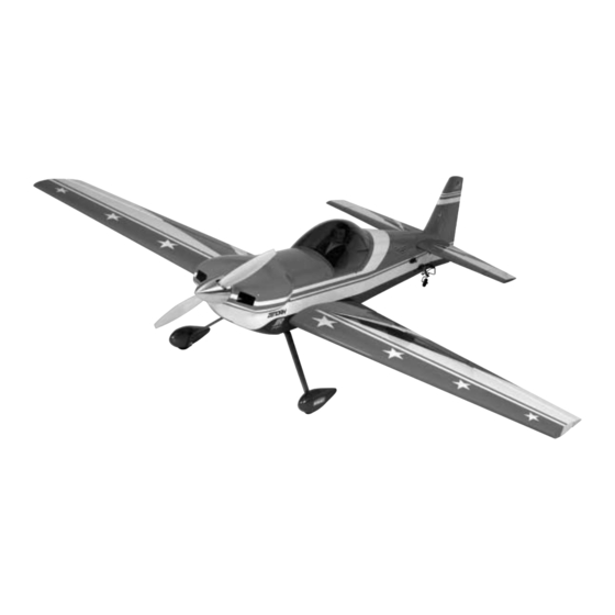
• 90% Custom built
• Designed by 8-time TOC competitor Mike McConville
• Specifically designed for excellence in precision and 3-D aerobatics
• Prepainted fiberglass cowl and wheelpants
• Plug-in wing and stab
• Precovered with genuine Hangar 9
• IMAC and Giant Scale legal
• Instructions include 3-D flying tips from Mike McConville
Specifications
Wingspan: . . . . . . . . . . . . . . . . . . . . . . . . . 97 in . . . . . . . . . 2,464 mm
Fuselage Length: . . . . . . . . . . . . . . . . . . . 90 in . . . . . . . . . 2,286 mm
Wing Area: . . . . . . . . . . . . . . . . . . . 1,750 sq in . . . . . . . . 112.9 dm sq
Flight Weight: . . . . . . . . . . . . . . . . . 23 to 26 lb . . . . . 10.4–11.8 kg
Recommended Engines: . . . . . . . . 60 to 80 cc – gasoline
WE GET PEOPLE FLYING
INSTRUCTION MANUAL
UltraCote
®
™
TM
TM
Advertisement
Table of Contents

Related Manuals for Hangar 9 Cap232


Summary of Contents for Hangar 9 Cap232
-
Page 1: Instruction Manual
• Designed by 8-time TOC competitor Mike McConville • Specifically designed for excellence in precision and 3-D aerobatics • Prepainted fiberglass cowl and wheelpants • Plug-in wing and stab • Precovered with genuine Hangar 9 UltraCote ® ™ • IMAC and Giant Scale legal •... -
Page 2: Table Of Contents
Table of Contents Introduction ............................3 Warning ............................... 3 Additional Required Equipment ......................4 Other Items Needed (not included in the kit) ..................5 Tools and Adhesives Needed (not included in the kit) ................5 Additional Needed Items ........................5 Contents of Kit ............................6 Section 1. -
Page 3: Introduction
The 1/3 Scale CAP 232 does not include hardware. Many experienced giant scale pilots have specific hardware preferences and can individually choose the components they prefer. Hangar 9 offers an optional Hardware Package (HAN1220-JR, HAN1221-FUT) that includes the hardware that our staff regularly uses and recommends. -
Page 4: Additional Required Equipment
Additional Required Equipment Radio Equipment with Computer Radio 1000mAh receiver battery pack or larger (4) Servos with 80 oz/in of torque minimum for elevator and rudder (JR8101, 4721, 2721, or 8411 or equivalent) (4) Servos with 60 oz/in of torque (aileron) (1) Servo for throttle (6) 24"... -
Page 5: Other Items Needed (Not Included In The Kit)
Small cable ties (2) Paper towels 2' gas compatible tubing Rubbing alcohol Cup engine mount B+B 6202 (G-62 only) Felt-tipped pen/pencil Coarse sandpaper Hangar 9 UltraCote (HANU887) Radio packing foam ® ™ (used for sealing aileron/elevator hinge gap) Antenna tube... -
Page 6: Contents Of Kit
(HANU870) Stabilizer Tubes (2) (HAN1257) Pearl Blue UltraCote ® (HANU845) Canopy (HAN1259) Included in the optional Hangar 9 ™ 1/3 Scale Hardware Package HAN1220-JR or HAN1221-Futaba) " Wheels (2) (DUB350L) 3/16" Main Axles (DUB249) " 4-40 Threaded Pro-Links (4) (HAN3556) Super Hinge Points (24) (ROB309) 5"... -
Page 7: Section 1: Installing The Wing To The Fuselage
Section 1: Installing the Wing to the Fuselage Parts Needed Tools and Adhesives Needed Left Wing Panel w/Aileron attached Thick CA glue (taped in place) (HAN1253) CA remover/debonder Right Wing Panel w/Aileron attached Hobby knife w/#11 blade (taped in place) (HAN1252) Drill Bit: 1/16"... -
Page 8: Section 2: Installing The Aileron Servos
All servos will have a slightly different JR’s 8411s offer a crisp response—the ultimate servo choice. neutral. If you are using Hangar 9 metal arms, they don’t all orient the same, (i.e., the spline is not oriented the same relative JR8101 Ultra Precision Wide Bearing to the arm). - Page 9 Section 2: Installing the Aileron Servos CONTINUED Step 4. Insert the servo with the 13" extension into the aileron Step 5. Using the screws included with the servos, fasten the cutout on the bottom of the wing closest to the wing root, as shown servos in place.
-
Page 10: Section 3: Installing The Aileron Control Horns
Tools and Adhesives Needed Wings with ailerons and servos 12" or longer ruler Drill Drill Bit: 5 /32" 8-32 Tap (DUB363) Included in Optional Hangar 9 ™ Hardware Package 30-minute epoxy Control Horns (4) Felt-tipped pen (Rocket City 8-32 Swivel Control Horn #ROC01B) - Page 11 Section 3: Installing the Aileron Control Horns CONTINUED Step 5. Using an 8-32 tap, tap the holes that you just drilled in Step 7. Screw the molded swivel links onto the inboard 8-32 the aileron. screw until the distance from the aileron surface to the bottom of the link is 5 /8".
-
Page 12: Section 4: Hinging And Sealing The Aileron Control Surfaces
Points in all giant scale aircraft. They are easy to install, very of just how much epoxy is needed. Wipe away any excess epoxy strong, and offer smooth friction-free control. The Hangar 9 with rubbing alcohol. Recheck that the center of the hinge point 1/3 Scale CAP 232 control surfaces are predrilled to use is flush and parallel with the trailing edge. - Page 13 Section 4: Hinging and Sealing the Aileron Control Surfaces CONTINUED Step 3. Allow the epoxy to fully cure for at least six hours. Step 6. Double-check the hinge gap and allow the epoxy to fully When cured, work each hinge throughout its full motion several cure for at least six hours.
- Page 14 Section 4: Hinging and Sealing the Aileron Control Surfaces CONTINUED Step 8. Cut two pieces of transparent UltraCote ® (not included) Step 11. Mark and cut both folded coverings to an overall for sealing the ailerons to approximately 3" x 42". Fold both length of 40".
-
Page 15: Section 5: Installing The Aileron Linkages
Hangar 9 also offers a Pro-Link Wrench (HAN3558) to make adjustments easier. - Page 16 Section 5: Installing the Aileron Linkages CONTINUED Step 5. Deflect the ailerons stick to full right. Hold it there Step 6. Attach the swivel clevis to the horn with the supplied (easiest way to have your TX set to PCM: hold and then turn off screw.
-
Page 17: Section 6: Installing The Rudder And Elevator Servos
Section 6: Installing the Rudder and Elevator Servos Parts Needed Fuselage Included in optional Hangar 9 ™ Hardware Kit 1" Heavy-Duty Servo Arms for Elevator (2) Not included (HAN3574-JR or HAN3575-Futaba) Servos (4) (a minimum of 80 oz/in of torque) "... - Page 18 Section 6: Installing the Rudder and Elevator Servos CONTINUED Step 2a. Install the servos in the fuselage tail section with the Step 3a. Using the screws included with the servos, fasten the output shaft to the rear as shown in the photo below. If using a servos in place.
-
Page 19: Section 7: Installing The Elevator, Control Horns, And Linkages
™ UltraCote (HANU887) Hex Wrench: 5/32" Sealing iron Hobby knife with #11 blade Included in Optional Hangar 9 ™ Hardware Package Robart Hinge Points (ROB309) Rocket City B-32 Swivel Control Horn (ROC01B) Control horns (2) 4-40 Ball Links (2) (ROC87) - Page 20 Section 7: Installing the Elevator, Control Horns, and Linkages CONTINUED Step 4. Mix a small amount of 30-minute epoxy and lightly coat Step 7. Locate the holes in each of the stabilizer’s top surface. the inside of the threaded holes and the 8-32 x 2" Rocket City The holes have been drilled for the 4-40 cap screw and split screw.
- Page 21 Locktite. Caution: Check the security of the screws before each flight. Step 11. Remove the servo arms from the elevator servos and replace them with Hangar 9 heavy-duty 1" arms. The arms need ™ to face up as shown in the photo below. Be sure to use a drop of...
-
Page 22: Section 8: Installing The Rudder, Control Horns, And Linkages
Section 8: Installing the Rudder, Control Horns, and Linkages Parts Needed Tools and Adhesives Needed Rudder Drill Fuselage Drill Bit: 5/32" Phillips screwdriver Not Included Straight screwdriver 8-32 Tap (DUB363) Control Horns (2) (ROCO1B) 30-minute epoxy 4-40 Ball Links (2) (ROC87) Rubbing alcohol 1/2"... - Page 23 Section 8: Installing the Rudder, Control Horns, and Linkages CONTINUED Step 5. Using a Moto-tool and a cut-off wheel, cut the bolt on Step 9. Remove the stock servo arms and replace them with the side with the head so that 1" of thread is exposed. heavy-duty 1 "...
-
Page 24: Installing The Landing Gear And Wheel Pants
Blue Locktite #4 washers (2) Aluminum Landing Gear (HAN1263) Fuselage ™ Included in optional Hangar 9 Hardware package " Wheels (2) (DUB350TL) " x 2" Axles (2) (DUB24) " Wheel Collars (4) (DUB141) Step 1. Install the axles in the landing gear as shown and Step 2. - Page 25 Section 9: Installing the Landing Gear and Wheel Pants CONTINUED Step 3. Drill a 3/8" hole at the marked position on the wheel Step 6. Install the 4-40 blind nut from inside the wheel pants pants. Be careful when drilling through the backside of the as shown.
- Page 26 Section 9: Installing the Landing Gear and Wheel Pants CONTINUED Step 9. Center the wheels in the wheel pants and tighten the Step 10. Mount the landing gear to the fuselage using four collars against the wheels so that they are held in place. Use blue 10-32 x 1"...
-
Page 27: Section 10: Attaching The Tail Wheel
Section 10: Attaching the Tail Wheel Parts Needed Tools and Adhesives Needed Fuselage Phillips screwdriver Drill Included in optional Hangar 9 ™ Hardware package Drill Bit: 1/8" Felt-tipped pen Ohio Superstar Large Tail Wheel Assembly (#OHI130) Not Included #6 x 3/4" Sheet Metal Screws (2) (DUB386) Step 1. -
Page 28: Section 11: Installing The Receiver, Battery, And Fuel Tank
Section 11: Installing the Receiver, Battery, and Fuel Tank Parts Needed Tools and Adhesives Needed Fuselage 5-minute epoxy Not Included 1000mAh or larger battery pack Receiver Receiver switch 1/8" light plywood Radio mounting foam (thick gyro tape also works well) Cup hooks Rubber bands #64 ®... - Page 29 Section 11: Installing the Receiver, Battery, and Fuel Tank CONTINUED ® Step 3. Using foam and rubber bands (or Velcro straps), Step 6. Using 5-minute epoxy, fasten the receiver mount in securely attach the battery to the battery tray. place as shown below. Step 4.
-
Page 30: Section 12: Mounting The Engine And Cowl
Section 12: Mounting the Engine and Cowl Parts Needed Included in Optional Hangar 9 ™ Hardware Package Fuselage Engine-mounting adapter plate (G-62 only) 6" 4-40 Rod Threaded (DUB802) Fiberglass cowl w/included mounting hardware 4-40 Solder Link (DUB604) 1/4" x 20 socket head cap screws,... - Page 31 Section 12: Mounting the Engine and Cowl CONTINUED Step 3. If using the GT-80 (or 445), the throttle servo is Step 6. Run the fuel lines from the pick up in the tank to the position as shown in the top of the engine box. Using a pen, carburetor and run the vent line out the bottom of the fire wall.
- Page 32 Section 12: Mounting the Engine and Cowl CONTINUED Using a G-62 Step 4. Mount the Zenoah throttle linkage to the engine as ® per the instructions included with the engine. Cut out the servo Step 1. Remove the metal engine mount (if attached) from the hole in the bottom plate as shown and mount the servo.
-
Page 33: Section 13: Hatch Assembly
Step 1. Glue a 1/3 scale pilot in the cockpit area (silicon glue Step 2. When satisfied with the cockpit detail, fit the canopy in works good here) and attach the instrument panel. Hangar 9 place. It may be necessary to trim the edges for a perfect fit. -
Page 34: Section 14: Balancing The Model
Section 14: Balancing the Model Tools Needed Felt-tipped pen Ruler Correctly balancing an aerobatic model is critical to its performance Step 2. Fully assemble the model. With a helper, lift the and flight characteristics. Checking the balance on giant scale airplane with your index fingers and find the balance point. -
Page 35: Section 16: Control Throws
Section 16: Control Throws Recommended Control Throws Standard Aileron " up 1 " down (18° up 17° down) " up 2 " down (37° up 35° down) Elevator " up 1 " down (16° up 16° down) 4" up 4" down (42° up 40° down) Rudder "... -
Page 36: Section 18: Setup And Flight Information By Mike Mcconville
Section 18: Setup and Flight Information by Mike McConville Our new 1/3 Scale CAP 232 will blow away almost any pilot The Prototype Model Setup wanting to fly aerobatics. When designing this model, I incorporated design features and enhancements that I used in All of the recommended settings in this manual are a result of the several Tournament of Champions and IMAC competitions. - Page 37 Section 18: Setup and Flight Information by Mike McConville CONTINUED Computer Radio Rates and Expos: When and Enhancements Where to Use Them A computer radio will allow you to do quite a bit of fine-tuning I always use Expo to soften the feel of the model. On high 3-D of the feel of the CAP 232, which will make aerobatics even rates I use quite a bit.
- Page 38 Section 18: Setup and Flight Information by Mike McConville CONTINUED CAP 232 at Its Best The Blender 3-D maneuvers (in simplest terms) are maneuvers performed by an airplane that are not usually done in a normal airplane flight path. What can be done with a 3-D plane is to make it fly like no other.
- Page 39 Section 18: Setup and Flight Information by Mike McConville CONTINUED Advanced recovery: Take the elevator all the way to the ground, adding some power before it touches down to slow the decent and transition into a Harrier and land. Add power to get the nose to rise to vertical and transition into a Torque Roll.
- Page 40 Section 18: Setup and Flight Information by Mike McConville CONTINUED The Torque Roll The Waterfall What it is: The CAP "hovers" vertically in place, rotating left around its roll axis. Setup: Full 3-D throws in elevator and rudder are a must. An aft CG helps a little.
- Page 41 Section 18: Setup and Flight Information by Mike McConville CONTINUED The Parachute The Wall What it is: The Parachute is a vertical dive that instantly What it is: The Wall is a Parachute turned on end. The model decelerates in its descent as it instantaneously corners into starts in normal level flight and suddenly corners nose up 90°, an Elevator.
-
Page 42: Ama Safety Code
AMA National Model Aircraft Safety Code Effective January 1, 2001 Model flying must be in accordance with this code in order for 9. I will not operate models with pyrotechnics (any device that AMA Liability Protection to apply. explodes, burns, or propels a projectile of any kind) including, but not limited to, rockets, explosive bombs dropped from General models, smoke bombs, all explosive gases (such as hydrogen-... -
Page 43: Ama National Model Aircraft Safety Code
AMA National Model Aircraft Safety Code Effective January 1, 2001 ORGANIZED RC RACING EVENT B. I will not fly my model aircraft in any organized racing event which does not comply with paragraph A above or which allows A. In every organized racing event in which contestants, callers, models over 20 pounds unless that competition event is AMA and officials are on the course: sanctioned. - Page 44 ©2001 Horizon Hobby, Inc. 4105 Fieldstone Road Champaign, IL 61822 www.horizonhobby.com HAN1250.46...
Need help?
Do you have a question about the Cap232 and is the answer not in the manual?
Questions and answers