Table of Contents
Advertisement
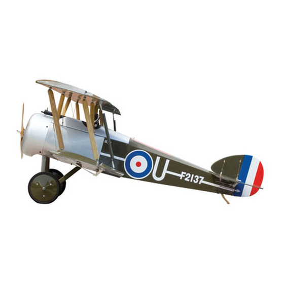
Sopwith Camel 60 ARF
Specifications
Wingspan. . .......................................61.in.(1551mm)
Wing.Area...........................1236.sq.in.(79.7.sq.dm)
Assembly mAnuAl
Length. . .........................................41.3.in.(1050mm)
Weight. . ..........................7.25–8.75.lb.(3.3kg–4.0kg)
®
Advertisement
Table of Contents

Related Manuals for Hangar 9 sopwith camel 60 arf


Summary of Contents for Hangar 9 sopwith camel 60 arf
- Page 1 ® Sopwith Camel 60 ARF Assembly mAnuAl Specifications Wingspan.........61.in.(1551mm) Length...........41.3.in.(1050mm) Wing.Area......1236.sq.in.(79.7.sq.dm) Weight......7.25–8.75.lb.(3.3kg–4.0kg)
-
Page 2: Table Of Contents
Table of Contents Contents.of.Kit..............3 ®... -
Page 3: Contents.of.kit
Contents of Kit Replacement Parts Items not shown A.. Fuselage. HAN4226 Tail.Skid. HAN4236 B.. Fuselage.Hatch. HAN4227 Pushrod.Set. HAN4237 C.. Top.Wing.Set. HAN4228 Flying.Wire.Set. HAN4238 D.. Bottom.Wing.Set. HAN4229 Aluminum.Wing.Tube. HAN4239 E.. Tail.Set. HAN4230 EP.Motor.Mount. HAN4245 F.. Landing.Gear. HAN4231 Glow.Motor.Mount. HAN40M G.. Wheel.Set. HAN4232 O-Rings.(10).(for.landing.gear). -
Page 4: Ultracote ® Covering Colors
UltraCote Covering Colors ® •.Olive.Drab. HANU904. •.White. HANU870 •.True.Red. HANU866. •.Deep.Blue. HANU873 •.Grey. HANU882. •.Silver. HANU881 Radio and Power Systems Requirements •.4-Channel.radio.system.(minimum).w/receiver •.. 5 37.Standard.Servo.(JRPS537).(5).or.equivalent. (4.required.when.building.the.electric.version) •.9".Servo.Lead.Extension.(JRPA097).(2) •.6”.Y-Harness.(JSP98020) JR XP6102 Recommended JR Systems JR XP9303 •.XP9303 •.XP6102 •.XP662 •.XF631 •.XF421EX Power 46 Brushless Recommended Power Systems Outrunner Motor, 670KV... -
Page 5: Required.tools.and.adhesives
Required Tools and Adhesives Tools •.Drill. •.T-pins •.Adjustable.wrench. •.Hex.wrench:.7/64",.3/32" •.Hobby.knife. •.Hobby.scissors •.Phillips.screwdriver. •.Pliers •.Side.cutters. •.Nut.driver:.5.5mm •.4-40.tap. . •.Tap.handle •.Crimping.tool •.. D rill.bits:.1/16".(1.5mm),.5/64".(2mm),.3/32".(2.5mm). 1/8".(3mm),.$43,.5/32".(4mm) Adhesives •.6-minute.epoxy.(HAN8000). •.30-minute.epoxy.(HAN8002) •.Thin.CA. . •.Canopy.glue •.Zap-A-Dap-A-Goo. •.Threadlock •.Medium.CA Other Required Items •.Epoxy.brushes. •.Felt-tipped.pen.or.pencil •.Measuring.device.(e.g..ruler,.tape.measure). •.Mixing.sticks.for.epoxy •.Paper.towels. •.Rubbing.alcohol •.Masking.tape. -
Page 6: Limited.warranty.period
Limited Warranty Period Horizon.Hobby,.Inc..guarantees.this.product.to.be.free.from.defects.in.both.material.and.workmanship.at.the.date.. of.purchase. Limited Warranty & Limits of Liability Pursuant.to.this.Limited.Warranty,.Horizon.Hobby,.Inc..will,.at.its.option,.(i).repair.or.(ii).replace,.any.product.determined. by.Horizon.Hobby,.Inc..to.be.defective..In.the.event.of.a.defect,.these.are.your.exclusive.remedies. This.warranty.does.not.cover.cosmetic.damage.or.damage.due.to.acts.of.God,.accident,.misuse,.abuse,.negligence,. commercial.use,.or.modification.of.or.to.any.part.of.the.product..This.warranty.does.not.cover.damage.due.to.improper. installation,.operation,.maintenance,.or.attempted.repair.by.anyone.other.than.an.authorized.Horizon.Hobby,.Inc..service. center..This.warranty.is.limited.to.the.original.purchaser.and.is.not.transferable..In.no.case.shall.Horizon.Hobby’s. liability.exceed.the.original.cost.of.the.purchased.product.and.will.not.cover.consequential,.incidental.or.collateral. damage..Horizon.Hobby,.Inc..reserves.the.right.to.inspect.any.and.all.equipment.involved.in.a.warranty.claim..Repair. or.replacement.decisions.are.at.the.sole.discretion.of.Horizon.Hobby,.Inc..Further,.Horizon.Hobby.reserves.the.right.to. change.or.modify.this.warranty.without.notice. REPAIR.OR.REPLACEMENT.AS.PROVIDED.UNDER.THIS.WARRANTY.IS.THE.EXCLUSIVE.REMEDY.OF.THE.CONSUMER.. HORIZON.HOBBY,.INC..SHALL.NOT.BE.LIABLE.FOR.ANY.INCIDENTAL.OR.CONSEQUENTIAL.DAMAGES. As.Horizon.Hobby,.Inc..has.no.control.over.use,.setup,.final.assembly,.modification.or.misuse,.no.liability.shall.be. assumed.nor.accepted.for.any.resulting.damage.or.injury..By.the.act.of.use,.setup.or.assembly,.the.user.accepts.all. resulting.liability. If.you.as.the.purchaser.or.user.are.not.prepared.to.accept.the.liability.associated.with.the.use.of.this.product,.you.are. advised.to.return.this.product.immediately.in.new.and.unused.condition.to.the.place.of.purchase. Safety Precautions This.is.a.sophisticated.hobby.product.and.not.a.toy..It.must.be.operated.with.caution.and.common.sense.and.requires. some.basic.mechanical.ability..Failure.to.operate.this.product.in.a.safe.and.responsible.manner.could.result.in.injury.or. damage.to.the.product.or.other.property..This.product.is.not.intended.for.use.by.children.without.direct.adult.supervision. The.product.manual.contains.instructions.for.safety,.operation.and.maintenance..It.is.essential.to.read.and.follow.all.the. instructions.and.warnings.in.the.manual,.prior.to.assembly,.setup.or.use,.in.order.to.operate.correctly.and.avoid.damage. or.injury. Questions, Assistance, and Repairs Your.local.hobby.store.and/or.place.of.purchase.cannot.provide.warranty.support.or.repair..Once.assembly,.setup.or.use. -
Page 7: Inspection.or.repairs
Inspection or Repairs If.your.product.needs.to.be.inspected.or.repaired,.please.call.for.a.Return.Merchandise.Authorization.(RMA)..Pack.the. product.securely.using.a.shipping.carton..Please.note.that.original.boxes.may.be.included,.but.are.not.designed.to. withstand.the.rigors.of.shipping.without.additional.protection..Ship.via.a.carrier.that.provides.tracking.and.insurance.for. lost.or.damaged.parcels,.as.Horizon.Hobby,.Inc..is.not.responsible.for.merchandise.until.it.arrives.and.is.accepted.at. our.facility..Include.your.complete.name,.address,.phone.number.where.you.can.be.reached.during.business.days,.RMA. number,.and.a.brief.summary.of.the.problem..Be.sure.your.name,.address,.and.RMA.number.are.clearly.written.on.the. shipping.carton. Warranty Inspection and Repairs To.receive.warranty.service,.you.must.include.your.original.sales.receipt.verifying.the.proof-of-purchase.date..Providing. warranty.conditions.have.been.met,.your.product.will.be.repaired.or.replaced.free.of.charge..Repair.or.replacement. decisions.are.at.the.sole.discretion.of.Horizon.Hobby. Non-Warranty Repairs Should.your.repair.not.be.covered.by.warranty.and.the.expense.exceeds.50%.of.the.retail.purchase.cost,.you.will.be. provided.with.an.estimate.advising.you.of.your.options..You.will.be.billed.for.any.return.freight.for.non-warranty.repairs.. Please.advise.us.of.your.preferred.method.of.payment..Horizon.Hobby.accepts.money.orders.and.cashiers.checks,.as. well.as.Visa,.MasterCard,.American.Express,.and.Discover.cards..If.you.choose.to.pay.by.credit.card,.please.include.your. credit.card.number.and.expiration.date..Any.repair.left.unpaid.or.unclaimed.after.90.days.will.be.considered.abandoned. and.will.be.disposed.of.accordingly. Electronics.and.engines.requiring.inspection.or.repair.should.be.shipped.to.the.following.address.(freight.prepaid): Horizon.Service.Center 4105.Fieldstone.Road Champaign,.Illinois.61822 All.other.products.requiring.inspection.or.repair.should.be.shipped.to.the.following.address.(freight.prepaid): Horizon.Product.Support 4105.Fieldstone.Road Champaign,.Illinois.61822... -
Page 8: Safety,.Precautions,.And.warnings
Safety, Precautions, and Warnings As.the.user.of.this.product,.you.are.solely.responsible.for.operating.it.in.manner.that.does.not.endanger.yourself.and. others.or.result.in.damage.to.the.product.or.the.property.of.others. Carefully.follow.the.directions.and.warnings.for.this.and.any.optional.support.equipment.(chargers,.rechargeable.battery. packs,.etc.).that.you.use.. This.model.is.controlled.by.a.radio.signal.that.is.subject.to.interference.from.many.sources.outside.your.control..This. interference.can.cause.momentary.loss.of.control.so.it.is.necessary.to.always.keep.a.safe.distance.in.all.directions.around. your.model,.as.this.margin.will.help.to.avoid.collisions.or.injury. •.Always.operate.your.model.in.an.open.area.away.from.cars,.traffic,.or.people. •.Avoid.operating.your.model.in.the.street.where.injury.or.damage.can.occur. •.Never.operate.the.model.out.into.the.street.or.populated.areas.for.any.reason. •.Never.operate.your.model.with.low.transmitter.batteries. •.. C arefully.follow.the.directions.and.warnings.for.this.and.any.optional.support.equipment.(chargers,.rechargeable. battery.packs,.etc.).that.you.use. •.Keep.all.chemicals,.small.parts.and.anything.electrical.out.of.the.reach.of.children. •.. M oisture.causes.damage.to.electronics..Avoid.water.exposure.to.all.equipment.not.specifically.designed.and.protected. for.this.purpose. Before Starting Assembly Before.beginning.the.assembly.of.the.Sopwith.Camel,.remove.each.part.from.its.bag.for.inspection..Closely.inspect.the. fuselage,.wing.panels,.rudder,.and.stabilizer.for.damage..If.you.find.any.damaged.or.missing.parts,.contact.the.place.of. purchase. If.you.find.any.wrinkles.in.the.covering,.use.a.heat.gun.or.sealing.iron.to.remove.them..Use.caution.while.working.around. areas.where.the.colors.overlap.to.prevent.separating.the.colors. HAN101 – Sealing Iron HAN100 – Heat Gun HAN141 –... -
Page 9: Section.1:.Cabane.strut.installation
Section 1: Cabane Strut Installation Required Parts .Step 2 •.Front.cabane.strut.(R&L) Use.four.4-40.x.1/2".socket.head.screws.to.secure.the. •.Rear.cabane.strut.(R&L) front.struts.to.the.fuselage..Blind.nuts.have.been.installed. inside.the.fuselage.for.the.screws.to.thread.into. •.4-40.x.1/2".socket.head.screw.(4) •.4-40.x.1/4".socket.head.screw.(4) Required Tools and Adhesives •.Hex.wrench:.3/32".. •.Threadlock With.so.many.parts.in.this.model,.we.are. going.to.start.with.some.easy.items.to.help. reduce.the.amount.of.parts.you.have.to. keep.track.of..The.best.way.to.do.this.is.to. attach.the.cabane.struts.to.the.fuselage. .Step 1 Locate.two.of.the.cabane.struts..Make.sure.you.grab.a. pair,.as.they.have.an.airfoil.shape.to.them..Slide.them.into. Note:.Make.sure.to.use.threadlock.on.all.four. the.slots.in.the.front.of.the.fuselage.behind.the.firewall. screws.to.prevent.them.from.vibrating.loose. with.the.wide.side.of.the.airfoil.towards.the.front,.just.like. a.wing..Check.that.the.tab.at.the.top.faces.away.from.the. centerline.of.the.fuselage. .Step 3 Slide.the.two.remaining.struts.into.the.slots.towards.the. -
Page 10: Section.2:.Landing.gear.installation
Section 1: Cabane Strut Installation Hint:.Check.the.positions.of.the.rear.tabs.in. .Step 4 comparison.to.the.front.tabs..They.should.be. Secure.the.struts.using.four.4-40.x.1/4".socket.head. parallel.to.each.other.and.to.the.top.of.the. screws..Again,.use.threadlock.on.the.screws.to.prevent. fuselage.opening..If.you.didn’t.see.it.back. them.from.vibrating.loose. in.Step.1,.you.will.certainly.notice.now. Section 2: Landing Gear Installation Required Parts .Step 1 •.Landing.gear.(R&L). •.Tail.skid Place.the.tail.skid.into.the.pre-drilled.hole.at.the.aft.end.. •.Steel.axle.guide.(2). •.3mm.setscrew.(2) of.the.fuselage. •.4mm.washer.(2). •.4mm.locknut.(2) •.Rubber.O-ring.(6). •.Scale.wheel.(2) •.Landing.gear.cross.brace •.Landing.gear.strap.(5) •.3mm.x.12mm.sheet.metal.screw.(10) Required Tools and Adhesives •.Hex.wrench.(included). - Page 11 Section 2: Landing Gear Installation .Step 2 .Step 4 Use.a.landing.gear.strap.and.two.3mm.x.12mm.sheet. Slide.the.landing.gear.cross.brace.through.the.landing. metal.screws.to.secure.the.tail.skid.into.position. gear..Make.sure.both.the.airfoils.are.facing.the.correct. direction,.and.that.the.flat.spot.in.the.axle.faces.toward.the. ground.when.the.plane.is.resting.upright.(or.away.from. the.fuselage). .Step 3 Place.either.the.right.or.left.landing.gear.into.position.on. the.bottom.of.the.fuselage..Use.two.landing.gear.straps. .Step 5 and.four.3mm.x.12mm.sheet.metal.screws.to.secure.the. gear.to.the.fuselage. Position.the.remaining.landing.gear.onto.the.fuselage,. passing.the.cross.brace.through.the.gear..Secure.the. landing.gear.to.the.fuselage.with.two.landing.gear.straps. and.four.3mm.x.12mm.sheet.metal.screws. Note:.Although.this.is.obvious,.the.gear. angles.out.away.from.the.fuselage.centerline. and.towards.the.front.of.the.fuselage.
- Page 12 Section 2: Landing Gear Installation Hint:.You.can.pre-stretch.the.O-rings.slightly. .Step 6 before.installing.them,.similar.to.that.of.pre- Attach.the.steel.axle.guide.to.the.landing.gear.using.a. stretching.a.balloon.before.blowing.it.up. 3mm.setscrew.and.threadlock..The.setscrew.tightens.. onto.the.flat.of.the.axle.to.keep.the.cross.brace.from. Note:.Rubber.bands.can.also.be.used. rotating..Position.the.second.steel.axle.guide.onto.the. in.place.of.the.O-rings.in.the.case.of. cross.brace..Secure.it.into.position.using.a.3mm.. an.O-ring.becoming.damaged. setscrew.and.threadlock. .Step 8 Slide.the.scale.wheel.onto.the.axle..Slide.a.4mm.washer. onto.the.axle,.and.then.tighten.a.4mm.nut.onto.the.axle.to. secure.the.wheel..Tighten.the.nut.enough.to.limit.the.play. of.the.wheel.on.the.axle,.but.leave.it.loose.enough.so.the. wheel.can.rotate.freely. Note:.It.may.be.necessary.to.adjust. the.steel.axle.guides.until.the.cross. brace.can.move.up.and.down.with. as.little.interference.as.possible. .Step 7 Place.three.rubber.O-rings.onto.the.landing.gear.as. shown..The.O-rings.will.keep.the.cross.brace.in.the. “down”.position.when.installed..The.O-rings.must.be.very. tight.to.stop.the.axle.from.rotating.
-
Page 13: Section.3A:.engine.installation
Section 3A: Engine Installation Required Parts .Step 2 •.8-32.washer.(12). •.8-32.locknut.(4) Position.the.engine.onto.the.engine.mount..Move.the. •.Fuel.tank. •.Tie-wrap.(2) engine.fore.and.aft.until.the.front.of.the.drive.washer.is. ".(140mm).from.the.front.of.the.firewall..Mark.the. •.Engine.mount.(R&L) locations.for.the.engine.mounting.bolts.onto.the.engine. •.8-32.x.1".machine.screw.(4) mount.using.a.felt-tipped.pen. •.8-32.x.1 ".machine.screw.(4) •.16 ".(420mm).pushrod.tube •.14 ".(362mm).threaded.pushrod.wire •.Nylon.clevis.w/retainer Required Tools and Adhesives •.Drill. •.Drill.bit:.5/32”.(4mm) •.Felt-tipped.pen. •.Threadlock •.Phillips.screwdriver. •.Engine •.Medium.grit.sandpaper. •.Side.cutters •.Rubbing.alcohol. •.Paper.towel •.Medium.CA ... - Page 14 Section 3A: Engine Installation .Step 4 .Step 6 Attach.the.engine.to.the.engine.mount.using.four.. Use.a.drill.and.5/32".(4mm).drill.bit.to.drill.the.location. 8-32.x.1 ".machine.screws,.four.8-32.lock.nuts.and. for.the.throttle.pushrod.tube. eight.#8.washers. Hint:.You.may.have.to.remove.the.engine. Hint:.If.you.are.having.trouble.getting.to.the. from.the.firewall.as.shown..Even.better. screws,.remove.the.mount.from.the.firewall. is.to.have.an.extended.length.drill.bit. and.install.the.screws.holding.the.engine.. that.can.reach.back.to.the.firewall. Reattach.the.mount.back.onto.the.firewall.once. the.engine.is.secure..This.is.also.helpful.with. .Step 7 the.Evolution..61.as.the.needle.valve.will.need. Roughen.the.throttle.pushrod.tube.using.medium.grit. to.be.removed.to.access.the.left.rear.screw. sandpaper..Wipe.the.tube.down.using.rubbing.alcohol. and.a.paper.towel.to.remove.any.oils.from.the.tube..Slide. .Step 5 the.tube.into.the.hole.in.the.firewall,.leaving.about.1/2". Use.a.felt-tipped.pen.to.mark.the.firewall.in.the.area.that. (13mm).protruding.from.the.firewall..Use.medium.CA.to. will.allow.the.throttle.pushrod.line.up.with.the.carburetor. glue.the.tube.to.the.firewall.
- Page 15 Section 3A: Engine Installation .Step 8 .Step 10 Use.side.cutters.to.trim.the.throttle.pushrod.tube.at.the. Slide.the.throttle.pushrod.into.the.throttle.pushrod.tube.. front.edge.of.the.servo.tray. Attach.the.clevis.to.the.throttle.arm.of.the.engine. .Step 9 .Step 11 Place.a.clevis.retainer.onto.a.nylon.clevis..Thread.the. Attach.the.muffler.to.the.engine..Adjust.the.output.. clevis.about.14.turns.onto.the.throttle.pushrod.wire. of.the.muffler.so.it.faces.down.and.away.from.the. fuselage..Use.the.instructions.provided.with.your.. engine.for.this.procedure.
- Page 16 Section 3A: Engine Installation .Step 12 .Step 14 Place.the.two.tie.wraps.into.the.fuselage.as.shown... Connect.the.lines.from.the.fuel.tank.to.the.engine..The.. Make.sure.you.will.be.able.to.access.them.once.the.. red.tube.goes.to.the.needle.valve,.while.the.green. fuel.tank.has.been.placed.into.the.fuselage,.as.these.. tube.goes.to.the.muffler..Trim.the.length.of.the.tube.as. will.hold.the.tank.in.position. necessary.to.prevent.them.from.getting.entangled.with.. the.engine.or.pushrod. .Step 13 Hint:.You.can.install.a.fuel.filler.valve.between. Place.the.fuel.tank.into.the.fuselage..The.stopper.in.the. the.fuel.tank.and.engine.to.make.fueling.easier. tank.faces.towards.the.bottom.of.the.fuselage..Slide.the. stopper.into.the.opening.of.the.firewall..Secure.the.fuel. tank.using.the.tie.wraps.placed.in.the.fuselage.in.the. previous.step. Hint:.Trim.the.excess.tie.wraps. using.side.cutters.for.a.cleaner. installation.of.the.fuel.tank.
-
Page 17: Section.3B:.electric.motor.installation
Section 3B: Electric Motor Installation Required Parts .Step 3 •.Fuselage. •.Motor.mount.side.(2) Mount.the.motor.to.the.motor.mount.front.using.hardware. •.8-32.washer.(8). •.8-32.locknut.(4) included.with.the.motor. •.Motor.mount.front •.8-32.x.1/2".machine.screw.(4) •.8-32.x.1/2".socket.head.screw.(4) Required Tools and Adhesives •.Phillips.screwdriver. •.Threadlock •.Hex.wrench:.7/64". •.Adjustable.wrench •.Soldering.iron. •.Solder •.Female.Deans.connector.w/wire •.Male.Deans.connector.(3) .Step 1 Attach.the.motor.mount.to.the.firewall.using.the.four.. 8-32.x.1/2".machine.screws.and.four.8-32.washers... .Step 4 Apply.threadlock.on.the.screws.to.prevent.them.from. Attach.the.motor.mount.front.to.the.motor.mount.sides. - Page 18 Section 3B: Electric Motor Installation .Step 5 .Step 7 Build.a.wiring.harness.for.the.batteries.using.a.female. Plug.the.motor.into.the.speed.control..Secure.the.batteries. connector.and.two.male.connectors..Follow.the.wiring.. using.the.hook.and.loop.strap..Plug.the.speed.control.into. in.the.photo.so.the.motor.sees.the.voltage.increase.of.. the.receiver..Mount.the.speed.control.inside.the.fuselage. the.two.batteries. so.it.will.not.interfere.with.the.installation.and.removal.of. the.batteries. .Step 6 Note:.Apply.a.piece.of.hook.and.loop.(not. Solder.the.appropriate.connectors.onto.the.speed.control. included).in.the.batteries.and.battery.tray.if. you.find.the.batteries.slide.forward.or.aft. .Step 8 Turn.on.the.radio.system..Plug.the.wiring.harness. assembled.in.Step.5.into.the.batteries.and.speed.control.. Use.the.throttle.on.the.transmitter.to.check.that.everything. is.working.correctly..Check.that.the.motor.is.rotating. counter-clockwise..If.not,.follow.the.directions.included. with.the.speed.control.to.correct.the.situation. .Step 9 Once.the.motor.is.working.and.rotating.in.the.correct. direction,.unplug.the.wiring.harness.for.safety.
-
Page 19: Section.4:.Cowling.installation
Section 4: Cowling Installation Required Parts .Step 2 •.Fuselage.assembly. •.Cowling Test.fit.the.cowling.onto.the.fuselage..Make.any.marks. •.Dummy.radial.engine. •#4.washer.(4) necessary.to.fit.the.cowling.over.the.engine..Use.hobby. scissors.and.a.rotary.tool.with.a.sanding.drum.to.trim.the. •.4-40.x.1/2".socket.head.screw.(4) cowl.to.fit. Required Tools and Adhesives •.6-minute.epoxy. •.Hobby.scissors •.Hobby.knife. •.Drill •.Drill.bit:.1/8".(3mm). •.Masking.tape •.Cardstock. •.Felt-tipped.pen The.installation.of.the.cowling.will. complete.the.main.fuselage.assembly.. We.can.then.move.along.to.getting. the.wings.prepped.and.installed. .Step 1 Use.a.hobby.knife.and.hobby.scissors.to.trim.the.material. from.between.the.cylinders.and.from.the.center.of.the. .Step 3 dummy.radial.engine. - Page 20 Section 4: Cowling Installation .Step 4 .Step 6 Cut.four.strips.of.card.stock.and.make.a.1/8".(3mm).. Drill.the.holes.in.the.cowl.for.the.mounting.screws.using.a. hole.in.the.end.of.each..Tape.the.card.stock.onto.the. 1/8".(3mm).drill.bit..Slide.a.#4.washer.onto.a.4-40.x.1/2". fuselage.so.the.holes.align.with.the.holes.in.the.cowl. socket.head.screw..Secure.the.cowling.using.four.of.the. mounting.blocks. 4-40.x.1/2".socket.head.screws. .Step 5 Note:.Cut.a.thin.5/64".(2mm).piece. of.the.fuel.tubing.to.slide.on.the.screw. Position.the.cowling.onto.the.fuselage..Trim.the.dummy. following.the.washer..This.will.help. radial.engine.as.necessary.to.fit.over.the.engine..The.cowl. prevent.the.screws.from.vibrating.loose. should.fit.onto.the.fuselage.so.the.drive.washer.extends. about.1/8".(3mm).or.so.in.front.of.the.dummy.radial.. .Step 7 Use.a.felt-tipped.pen.to.transfer.the.position.for.the.cowl. mounting.screws.onto.the.cowl. Install.an.appropriate.propeller.for.your.selected.engine.
-
Page 21: Section.5:.Aileron.servo.installation
Section 5: Aileron Servo Installation Required Parts .Step 2 •.Bottom.wing.(R&L) Remove.the.servo.hatch.from.the.wing..Place.the.servo. •.. 5 /8".x.7/16".x.7/16".(16mm.x.11mmx.11mm). onto.the.hatch,.centering.the.servo.arm.in.the.opening.. aileron.servo.block.(4) Also.position.the.servo.so.the.centerline.of.the.arm.is. aligned.with.the.edge.of.the.hatch.to.prevent.interference. •.2mm.x.10mm.sheet.metal.screw.(8) between.the.arm.and.the.wing.or.hatch..Use.a.felt-tipped. •.Control.horn.w/backplate.(2) pen.to.transfer.the.location.of.the.servo.onto.the.hatch. •.2mm.x.20mm.sheet.metal.screw.(6) •.3 ".(86mm).threaded.pushrod.wire.(2) •.Nylon.clevis.w/retainer.(2) •.Pushrod.connector.(2) Required Tools and Adhesives •.Aileron.servo.(2). •.6-minute.epoxy •.Felt-tipped.pen. •.Drill •.Side.cutters. •.Hobby.knife •.Phillips.screwdriver •.Servo.extension,.18".(457mm) •.Drill.bit:.1/16".(1.5mm),.3/32".(2.5mm) Although.there.are.four.ailerons.to.deal.with,. - Page 22 Section 5: Aileron Servo Installation .Step 4 .Step 7 Once.the.blocks.have.been.positioned.and.the.servo.will. Thread.a.clevis.onto.one.of.the.longer.pushrod.wires.. fit.between.the.block,.use.6-minute.epoxy.to.glue.the. Pass.the.wire.into.the.wing..Attach.the.servo.extension.to. blocks.securely.to.the.hatch. the.clevis.and.pull.it.through.the.wing. Note:.The.block.must.be.glued.to.the.hatch. so.they.won’t.pop.loose..Remember.we.have. the.load.of.two.ailerons.being.transferred. to.the.servo.and.blocks,.not.just.one. .Step 5 Once.the.epoxy.has.fully.cured,.position.the.servo.back. onto.the.servo.hatch.between.the.blocks..Use.a.felt-tipped. pen.to.mark.the.location.for.the.servo.mounting.screws. .Step 6 Use.a.1/16".(1.5mm).drill.bit.to.drill.the.four.locations. marks.in.the.previous.step..Attach.the.servo.to.the.blocks. using.the.screws.provided.wit.the.servo..Use.side.cutters. to.trim.the.excess.arm.so.only.the.portion.of.the.servo. Hint:.You.can.tie.a.weight.to.a. arm.extending.to.the.outside.of.the.hatch.remains. string.and.use.that.as.well.to.pull.
- Page 23 Section 5: Aileron Servo Installation .Step 8 .Step 10 Secure.the.servo.hatch.to.the.wing.using.four.. Remove.the.backplate.from.the.control.horn.using.a.. 2mm.x.10mm.sheet.metal.screws. sharp.hobby.knife..Attach.the.clevis.to.the.middle.hole.. of.the.control.horn..Position.the.horn.onto.the.wing.so.. the.holes.in.the.horn.align.with.the.hinge.line.of.the. aileron..The.pushrod.wire.will.run.to.the.outside.of.the. servo.horn.and.be.parallel.to.the.horn.as.well..Use.a.. felt-tipped.pen.to.mark.the.locations.for.the.three.control. horn.mounting.screws. Hint:.Use.a.T-pin.to.poke.through.the. covering.on.the.backside.of.the.hatch.to.leave. indications.where.the.holes.are.in.the.hatch. .Step 9 Locate.the.3 ".(86mm).pushrod.wire,.nylon.clevis.and. .Step 11 clevis.retainer..Slide.the.retainer.onto.the.clevis,.and.then. Drill.the.three.locations.for.the.control.horn.screws.using. thread.the.clevis.about.14.turns.onto.the.pushrod.wire. a.3/32".(2.5mm).drill.bit..Apply.a.couple.drops.of.thin.CA. into.each.of.the.holes.to.harden.the.underlying.balsa.
- Page 24 Section 5: Aileron Servo Installation Hint:.Wrap.a.small.piece.of.low-tack.tape. .Step 12 around.the.aileron.and.wing.to.hold.the. Attach.the.control.horn.to.the.aileron.using.three.2mm.x. aileron.in.the.neutral.position..This.will. 20mm.sheet.metal.screws.and.the.control.horn.backplate. come.in.handy.when.installing.the.linkage. between.the.upper.and.lower.ailerons. .Step 14 Use.pliers.to.bend.the.pushrod.at.a.90-degree.angle.at.the. mark.made.in.the.last.step..Enlarge.the.holes.in.the.servo. arm.using.a.5/64".(2mm).drill.bit..Pass.the.bend.through. the.outer.hole.and.secure.the.pushrod.wire.to.the.arm. using.a.pushrod.connector. Hint:.Use.side.cutters.to.remove.the.excess. .Step 13 pushrod.wire..Use.a.file.to.smooth.the.end.of. Make.sure.the.aileron.servo.is.centered.using.the.radio. the.cut.so.it.doesn’t.snag.on.your.shirt.or.skin. system..Center.the.aileron.and.use.a.felt-tipped.pen.to. mark.the.aileron.pushrod.where.it.crosses.the.servo.arm. .Step 15 Repeat.Steps.1.through.14.for.the.remaining.aileron.servo.
-
Page 25: Section.6:.Bottom.wing.installation
Section 6: Bottom Wing Installation Required Parts .Step 2 •.Bottom.wing.(R&L). •.Wing.tube After.drilling.the.hole,.use.a.4-40.tap.to.tap.the.hole.. •.4-40.x.1/2".socket.head.screw.(4) for.the.screw. •#4.washer.(4) Required Tools and Adhesives •.Drill. •.Drill.bit:.#43 •.4-40.tap. •.Threadlock Installing.the.bottom.wing.isn’t.tricky,.but. will.require.drilling.and.tapping.a.couple. of.holes..Once.the.bottom.wing.is.in.place,. we.can.move.on.to.installing.the.top.wing,. making.this.look.more.like.a.biplane. .Step 1 Slide.the.wing.tube.into.one.of.the.bottom.wing.panels.. Hint:.It.is.easier.to.leave.the.tube.in. Carefully.drill.a.#43.hole.into.the.wing.tube,.being.careful. position.when.tapping.the.hole..This. not.to.damage.the.wing. will.make.lining.up.the.hole.in.the.wing. much.easier.in.the.following.step. .Step 3 Use.a.4-40.x.1/2".socket.head.screw.and.#4.washer.to. - Page 26 Section 6: Bottom Wing Installation .Step 4 .Step 6 Slide.the.wing.(and.tube).into.the.fuselage..Carefully.push. Slide.the.remaining.wing.panel.into.position..While. the.wing.tight.against.the.fuselage,.and.then.use.a.#43. holding.it.tight.against.the.fuselage,.drill.the.hole.for.the. drill.to.drill.for.the.anti-rotation.screw.through.the.hole.in. wing.tube.and.the.anti-rotation.pin..After.threading.both. the.fuselage..Again,.use.care.not.to.let.the.drill.bit.slip.and. holes,.secure.the.wing.using.two.4-40.x.1/2".socket.head. damage.the.fuselage.or.wing. screws.and.two.#4.washers. .Step 5 Hint:.When.removing.the.bottom.wing,. remove.the.three.socket.head.screws.that.do. Use.a.4-40.tap.to.thread.the.hole..Secure.the.wing.to.. not.have.threadlock..Leaving.the.final.screw.in. the.fuselage.using.a.4-40.x.1/2".socket.head.screw.and.. place.will.save.you.some.time.in.trying.to.line. a.#4.washer. up.the.hole.with.the.screw.in.the.wing.tube.
-
Page 27: Section.7:.Top.wing.installation
Section 7: Top Wing Installation Required Parts .Step 1 •.Covering.(green). •.Covering.(grey) Locate.the.wing.joiner.and.the.joiner.dowel..Test.fit.them. •.4-40.locknut.(8). •#4.washer.(4) into.one.of.the.top.wing.panels. •.Top.wing.(R&L) •.. W ing.joiner.(5 ".x.1/2".x.3/16"). (150mm.x.13mm.x.5mm) •.Joiner.dowel.(1/4".x.2 ").(6mm.x.60mm) •.4-40.x.1/2".socket.head.screw.(12) •.4-40.x.5/8".socket.head.screw.(8) •.Interplane.strut.(long).(2) •.Interplane.strut.(short).(2) •.Interplane.bracket.(8) •.Aileron.slave.linkage.control.horn.(grey).(2) •.Aileron.slave.linkage.control.horn.(green).(2) •.Aileron.slave.linkage.(2) •.Nylon.clevis.w/retainer.(4) .Step 2 Required Tools and Adhesives Test.fit.the.remaining.panel.onto.the.joiner.and.dowel... - Page 28 Section 7: Top Wing Installation Note:.The.squared.end.of.the. .Step 3 bracket.is.the.one.the.screw.goes. Once.the.two.panels.have.been.fit.together,.mix.up.about. through.to.attach.to.the.wing. 1/2.oz..(15ML).of.30-minute.epoxy..Apply.the.epoxy.to. all.sides.of.the.joiner.and.to.the.joiner.dowel..Also.apply. Hint:.If.you.are.planning.on.installing. epoxy.to.the.openings.in.the.panels.where.the.joiner.and. the.rigging.between.the.top.and.bottom. dowel.fit..Slide.the.joiner.and.dowel.into.the.panel..Then. wings,.you.may.want.to.take.a.quick.look. slide.the.remaining.panel.into.position..Use.a.paper.towel. at.Section.10:.Rigging.Installation.before. and.rubbing.alcohol.to.remove.excess.epoxy..Use.tape.to. installing.the.brackets.and.attaching. hold.the.two.panels.together.until.the.epoxy.fully.cures. the.top.wing.to.the.cabane.struts. .Step 5 Attach.four.interplane.brackets.to.the.top.of.the.bottom. wing.using.four.4-40.x.1/2".socket.head.screws..The. brackets.face.towards.the.wing.tip.of.their.respective.wing. panels..Leave.the.screw.slightly.loose.for.now.so.the. brackets.can.be.adjusted.when.installing.the.interplane. struts. .Step 4 Attach.four.interplane.brackets.to.the.bottom.of.the.. top.wing.using.four.4-40.x.1/2".socket.head.screws... The.brackets.face.towards.the.wing.tip.of.their.respective. wing.panels..Leave.the.screws.slightly.loose.for.now..
- Page 29 Section 7: Top Wing Installation Note:.Once.the.struts.have.been.attached,. .Step 6 check.that.they.are.in.line.with.each.other.. Use.four.4-40.x.1/2".socket.head.screws.to.attach.the.top. This.is.done.by.tweaking.the.brackets.slightly.. wing.to.the.cabane.struts. Once.aligned,.the.brackets.can.be.fully. tightened.and.threadlock.placed.on.each.of. the.screws.holding.the.brackets.to.the.wing. .Step 8 Lightly.sand.the.bottom.of.the.aileron.slave.linkage. control.horns.to.remove.the.paint.where.they.will.be. inserted.into.the.wing. .Step 7 Locate.the.interplane.struts..There.are.two.shorter.struts. that.are.positioned.at.the.leading.edge.of.the.wing..The. two.shorter.struts.positioned.at.the.trailing.edge.of.the. wing..Install.the.interplane.struts.between.the.top.and. bottom.wing.using.eight.4-40.x.5/8".socket.head.screws. and.eight.4-40.locknuts.
- Page 30 Section 7: Top Wing Installation .Step 9 .Step 10 Use.6-minute.epoxy.to.glue.the.aileron.slave.linkage. Complete.the.aileron.slave.linkage.by.placing.a.clevis. control.horns.into.the.slots.in.the.upper.and.lower. retainer.onto.a.clevis..Thread.the.clevis.onto.the.threaded. ailerons..Remember.to.place.the.green.horn.into.the.top.of. end.of.the.linkage..Repeat.for.both.ends.of.the.linkage. the.ailerons.so.it.blends.with.the.covering.on.the.wing. .Step 11 With.the.radio.system.on.and.the.aileron.servos.operating,. attach.the.slave.linkage.to.the.bottom.aileron..Thread. the.clevises.either.in.or.out.so.when.the.top.clevis.is.in. position,.the.top.aileron.is.centered. Note:.Be.careful.not.to.push.the.horn. through.the.opposite.side.of.the.ailerons.
-
Page 31: Section.8:.Tail.installation
Section 8: Tail Installation Required Parts .Step 2 •.Rudder. •.Elevator.(2) Test.fit.the.tab.from.the.fin.into.the.slot.in.the.stabilizer.. •.Fin. •.Stabilizer Use.a.square.to.check.the.alignment.of.the.fin.to.the. stabilizer..Lightly.sand.the.tab.on.the.fin.if.necessary.for. •.CA.hinge.(9) alignment.purposes. Required Tools and Adhesives •.30-minute.epoxy. •.Paper.towel •.Rubbing.alcohol. •.Hobby.knife •.T-pins. •.Drill •.Drill.bit:.1/16".(1.5mm) This.is.the.last.major.airframe. assembly.before.moving.on.to.the.radio. installation.and.installing.the.rigging.. After.installing.the.tail,.you’ll.get.to.see. exactly.what.your.Sopwith.looks.like. .Step 1 Locate.the.stabilizer.and.fin..Remove.the.tape.holding. .Step 3 the.elevators.from.the.stabilizer,.and.the.tape.holding.the. - Page 32 Section 8: Tail Installation .Step 5 .Step 7 Carefully.remove.the.covering.from.the.stabilizer.. Use.a.felt-tipped.pen.to.trace.the.outline.of.the.fuselage. saddle.on.the.fuselage..Do.not.change.the.shape.of.. onto.the.bottom.of.the.stabilizer..Also.trace.the.top.of.the. the.saddle.by.accident. fuselage.where.it.meets.the.stabilizer. .Step 6 Slide.the.stabilizer.assembly.onto.the.fuselage..Check.that. the.stabilizer.is.parallel.to.the.wings,.and.that.the.fin.runs. down.the.centerline.of.the.fuselage. Parallel Note:.You.will.want.to.have.as.much. gluing.surface.as.possible.to.secure. the.stabilizer.to.the.fuselage. Hint:.It.is.easier.to.reference.the.top. wing.and.stabilizer.as.the.top.wing.has. less.dihedral.than.the.bottom.wing.
- Page 33 Section 8: Tail Installation .Step 8 .Step 10 Use.a.sharp.hobby.knife.to.remove.the.covering.. Use.a.1/16".(1.5mm).drill.bit.to.drill.a.hole.in.the.center.of. 1/16”.(1.5mm).inside.the.lines.drawn.on.the.stabilizer. each.hinge.slot.in.one.of.the.elevators..Drill.holes.in.the. corresponding.hinge.slots.for.the.stabilizer. Important:.DO.NOT.cut.into.the.stabilizer.. Use.very.light.pressure.to.trim.the. .Step 11 covering..You.can.also.use.a.hot.knife.or. Place.a.T-pin.in.the.center.of.three.hinges. soldering.iron.to.remove.the.covering. .Step 9 Mix.up.1/2.Oz..(15ML).of.30-minute.epoxy..Apply.the. epoxy.to.the.stabilizer.saddle,.the.bare.wood.on.the. stabilizer,.and.onto.the.fin.where.it.fits.into.the.fuselage.. Check.the.alignment.of.the.stabilizer.often.to.make.sure.it. remains.in.position.while.the.epoxy.cures. Note:.Clean.up.any.excess.epoxy.using. a.paper.towel.and.rubbing.alcohol. Hint:.Once.the.epoxy.has.fully.cured,.you. can.take.the.wings.off.your.Sopwith.to.make. it.easier.to.work.on.in.your.work.area.
- Page 34 Section 8: Tail Installation .Step 12 .Step 14 Slide.the.hinges.into.the.slots.in.the.elevator. Remove.the.T-pins.from.the.hinges..Apply.thin.CA.to.. each.of.the.hinges,.both.top.and.bottom. .Step 13 Note:.DO.NOT.use.accelerator.when.gluing. Slide.the.elevator.into.position.on.the.stabilizer..Make. the.hinges..The.CA.MUST.be.given.time.to. sure.the.colors.match.up,.and.that.the.end.of.the.elevator. soak.into.the.hinge.to.provide.the.best.bond. aligns.with.the.stabilizer. between.the.hinge.and.control.surface. .Step 15 Pull.on.the.elevator.and.stabilizer.to.check.that.the.hinges. are.glued.securely..Use.care.not.to.use.too.much.pressure. and.damage.your.aircraft.
- Page 35 Section 8: Tail Installation .Step 16 .Step 17 Once.the.CA.has.fully.cured,.flex.the.elevator.up.and.down. Repeat.Steps.10.through.16.for.the.remaining.elevator. a.few.times.to.break.in.the.hinges. hinges.and.for.the.rudder.hinges.
-
Page 36: Section.9:.Radio.installation
Section 9: Radio Installation Required Parts .Step 2 •.Fuselage.assembly. •.Pilot.figure Locate.the.22 ".(578mm).“Y”.threaded.pushrod.and. •.22 ".(570mm).threaded.pushrod slide.it.into.the.tubes.installed.in.the.fuselage..Take.your. time.as.this.can.be.a.little.tricky..This.pushrod.will.be. •.22 ".(578mm).“Y”.threaded.pushrod used.for.the.elevators. •.Nylon.clevis.w/retainer.(3) •.Pushrod.connector.(2) •.Control.horn.w/backplate.(3) •.2mm.x.12mm.machine.screw.(9) •.Brass.pushrod.connector •.Connector.backplate •.3mm.x.6mm.machine.screw Required Tools and Adhesives •.Standard.servo.w/hardware.(3) •.Receiver. •.Zap-A-Dap-A-Goo •.Receiver.battery. •.Switch.harness •.Phillips.screwdriver. •.Hobby.knife •.Felt-tipped.pen. •.Drill ... - Page 37 Section 9: Radio Installation .Step 4 .Step 6 Use.a.hobby.knife.to.carefully.remove.the.backplate.from.a. Secure.the.control.horn.to.the.rudder.using.three.2mm.x. control.horn..Attach.the.clevis.for.the.rudder.pushrod.onto. 12mm.machine.screws.and.the.control.horn.backplate. the.control.horn..Position.the.horn.so.the.holes.for.the. clevis.align.with.the.hinge.line..Use.a.felt-tipped.pen.to. transfer.the.mounting.holes.onto.the.rudder. .Step 5 Use.the.marks.made.in.the.last.step.to.drill.3/32".(2.5mm). holes.through.the.rudder.for.mounting.the.control.horn.. Apply.a.drop.or.two.of.thin.CA.to.each.hole.to.harden.the. underlying.balsa.
- Page 38 Section 9: Radio Installation .Step 7 .Step 8 Repeat.Steps.4.through.6.for.the.elevator.control.horns.. Install.the.grommets.and.brass.eyelets.in.the.servo.using. Make.sure.you.position.the.horns.the.same.for.the.right. the.instructions.that.came.with.your.servo.or.radio.system.. and.left.elevators. Place.the.rudder.servo.into.the.servo.tray..Position.the. servo.so.the.servo.horn.aligns.naturally.with.the.rudder. pushrod..Mark.the.locations.for.the.servo.screws.using.a. felt-tipped.pen. .Step 9 Use.a.drill.and.1/16".(1.5mm).drill.bit.to.drill.the.locations. from.the.previous.step. Note:.The.elevators.may.not.be.aligned. once.the.horns.are.installed..Once.the. servo.has.been.installed.and.connected. to.the.pushrod,.we’ll.come.back.and. correct.any.alignment.problems.
- Page 39 Section 9: Radio Installation .Step 10 .Step 12 Use.the.hardware.provided.with.the.servo.to.secure.its. Use.pliers.to.bend.the.rudder.pushrod.at.a.90-degree. location.on.the.servo.tray. angle.at.the.mark.made.in.the.last.step..Enlarge.the.holes. in.the.servo.arm.in.the.vicinity.of.the.pushrod.using.a. 5/32".(2mm).drill.bit..Pass.the.pushrod.through.the.servo. arm.and.use.a.pushrod.connector.to.secure.the.pushrod. to.the.servo.arm. .Step 11 Plug.the.rudder.servo.into.the.receiver..Turn.on.the. transmitter.and.receiver.and.center.the.trim.and.rudder. stick.on.the.transmitter..Position.the.rudder.so.it.is.. Note:.Trim.the.excess.arms.from.the.servo. in.line.with.the.fin.(neutral)..Use.a.felt-tipped.pen.to.. to.prevent.them.from.interfering.with.the. mark.the.rudder.pushrod.where.it.crosses.the.holes.in.. operation.of.the.rudder.and.associated.linkage. the.servo.arm. .Step 13 Repeat.Steps.8.though.12.for.the.elevator.servo.and. linkage..You.can.center.either.the.right.or.left.elevator.half. before.marking.the.pushrod.wire.as.described.in.Step.11.
- Page 40 Section 9: Radio Installation .Step 14 .Step 16 The.elevator.you.did.not.choose.to.center.in.the.. Plug.the.throttle.servo.into.the.receiver..Turn.on.the. previous.step.may.need.to.be.adjusted..Simply.. transmitter.and.receiver.and.center.the.throttle.stick.. disconnect.the.clevis.from.the.control.horn.and.thread.. and.trim..Check.that.the.position.of.the.servo.arm.is.. the.clevis.in.or.out.until.both.elevator.halves.are. as.shown.in.the.previous.step..If.not,.remove.the.arm. positioned.parallel.to.each.other. and.move.it.as.such..This.will.provide.an.equal.amount. of.throw.for.both.low.and.high.throttle.settings,.making. setting.up.the.linkage.easier. .Step 17 Remove.the.arm.from.the.servo.and.enlarge.the.holes. in.the.arm.that.correspond.with.the.linkage.(and.the. last.step).using.a.5/64".(2mm).drill.bit..Slide.the.brass. pushrod.connector.into.the.hole.and.secure.it.using.the. connector.backplate. .Step 15 Use.the.procedure.as.described.in.Steps.8.through.10.to. mount.the.throttle.servo.into.the.fuselage..Make.sure.the. servo.arm.won’t.interfere.with.the.operation.of.the.rudder. or.elevator.linkages.when.positioning.the.throttle.servo. .Step 18 Slide.the.throttle.pushrod.into.the.brass.pushrod.
- Page 41 Section 9: Radio Installation .Step 19 .Step 22 Use.the.transmitter.to.check.that.the.carburetor.moves. Plug.the.switch.harness.into.the.receiver.and.receiver. through.its.full.range.of.motion..If.it.binds.at.either.low.. battery..Secure.the.switch.in.the.pre-cut.opening.in.the. or.high.throttle,.move.the.linkage.toward.the.center.of.. side.of.the.fuselage..Route.the.antenna.wire.from.the. the.servo.arm,.or.away.from.the.center.at.the.throttle.. receiver.to.the.tail.of.the.plane. arm..If.it.doesn’t.make.it.fully.closed.or.open,.move.. the.linkage.away.from.the.center.of.the.servo.arm,.or. toward.the.center.of.the.throttle.arm..It.may.take.some. time.to.get.things.in.the.right.position,.but.it.is.well.. worth.it.at.the.field. .Step 20 Wrap.the.receiver.and.receiver.battery.in.foam.to.protect. them.from.vibration. Note:.Do.not.cut.the.antenna.wire.. Doing.so.will.reduce.the.range.of. your.particular.radio.system. .Step 23 Secure.the.pilot.to.the.hatch.using.Zap-A-Dap-A-Goo. .Step 21 Place.the.receiver.and.receiver.battery.into.the.fuselage.. Secure.their.position.using.straps.or.by.gluing.braces. inside.the.fuselage.
-
Page 42: Section.10:.Rigging.installation
Section 10: Rigging Installation Required Parts Note:.There.are.two.types.of.brass.fittings.. One.has.holes.that.are.equal.size.which. •.Complete.airframe. •.Brass.adjusters.(16) are.used.primarily.on.the.tail..The.other. •.2-56.nut.(6). •.Cable.crimp.(32) fittings.have.holes.of.unequal.size.and. •.Brass.fitting.(equal.hole.size).(18) are.used.when.rigging.the.wings. •.Brass.fitting.(unequal.hole.size).(14) •.2-56.x.5/8".machine.screw.(4) Hint:.Make.a.slight.bend.in.each.of.the. •.2-56.x.3/8".machine.screw.(2) brass.fittings.before.installing.them. •.Cable.end.(right-hand.thread).(16) •.Cable.end.(left-hand.thread.(16) .Step 2 Install.the.two.brass.fittings.on.the.bottom.of.the.fuselage.. Required Tools and Adhesives as.shown. •.Hobby.knife. •.Plies.or.crimping.tool •.Side.cutters The.last.thing.to.do.is.to.install.the.rigging.. Although.this.is.one.section,.it.can.be. classified.as.two.independent.rigging. procedures:.rigging.the.tail.and.rigging.the. wings..You.MUST.install.the.rigging.on. the.tail.or.it.could.possibly.fail.in.flight..The. - Page 43 Section 10: Rigging Installation Step 4 Step 6 Cut.the.cable.into.four.7".(172mm).pieces..Prepare.one. Repeat.Step.4,.only.passing.the.cable.through.the.brass. cable.by.sliding.the.cable.through.a.crimp,.through.the. fittings.instead.of.the.cable.ends..The.cables.should.have. cable.end,.then.back.through.the.crimp..Pull.the.excess. very.light.tension. cable.tight.and.use.a.crimping.tool.to.complete.the.job.. Repeat.for.four.of.the.ends. .Step 7 Repeat.Steps.3.through.6.for.the.cables.on.the.bottom.of. the.stabilizer. Step 5 Attach.the.four.connectors.to.the.brass.fittings.. .Step 8 on.the.top.of.the.stabilizer. Locate.eight.of.the.brass.fittings.with.unequal.size.holes.. Attach.the.fittings.under.the.strut.fittings.as.shown.
- Page 44 Section 10: Rigging Installation .Step 9 .Step 11 Install.the.wings.onto.the.fuselage..When.installing.the. Attach.the.longer.rigging.to.the.rear.fitting.at.the.top.. top.wing,.place.four.brass.fittings.with.unequal.size.holes. wing.strut..Guide.the.cable.through.the.hole.in.the.top. under.the.cabane.struts. of.the.bottom.wing.and.out.the.hole.in.the.bottom.of.the. bottom.wing. .Step 10 Install.the.shorter.rigging.between.the.cabane.struts.and. the.bottom.wing..Leave.the.tension.loose.on.the.cables. Note:.This.cable.will.pass.between. the.cables.installed.in.Step.10.
- Page 45 Section 10: Rigging Installation .Step 12 Attach.the.brass.fitting.with.equal.size.holes.so.the.cable. will.pass.through.the.holes.in.the.top.and.bottom.of.the. bottom.wing..Use.a.#2.x.3/8".sheet.metal.screw.to.secure. the.fitting.to.the.bottom.of.the.fuselage. .Step 15 Repeat.Steps.9.through.14.for.the.rigging.on.the.other. side.of.the.fuselage. .Step 16 Now.you.can.go.back.and.apply.tension.to.the.rigging.. .Step 13 for.the.tail.and.wings..The.rigging.must.have.VERY.. Attach.a.fitting.right.behind.the.landing.gear..Use.a.. LIGHT.tension..Applying.too.much.tension.can.place. #2.x.3/8".sheet.metal.screw.to.secure.the.fitting. unwanted.loads.on.the.airframe.and.even.pull.the.tail.. or.wing.out.of.alignment. .Step 14 Install.the.longer.rigging.between.the.fuselage.and.the.top. wing..Again,.leave.the.tension.off.the.rigging.at.this.time.
-
Page 46: Section.11:.Center.of.gravity.(Cg)
Section 11: Center of Gravity (CG) Required Parts .Step 2 •.Complete.airframe. •.Weight.box Install.the.hatch.before.checking.the.Center.of.Gravity. •.8-32.x.5/8".machine.screw.(3) •#8.washer Required Tools and Adhesives •.Felt-tipped.pen. •.Phillips.screwdriver An.important.part.of.preparing.the. aircraft.for.flight.is.properly.balancing. the.model..This.is.especially.important. when.various.engines.are.mounted. Caution: Do not inadvertently skip this step! Note:.Because.we.felt.it.is.most.important. .Step 3 to.preserve.accurate.scale.lines.of.the. Make.sure.the.aircraft.is.upright.when.measuring.the.CG.. Sopwith.Camel,.the.nose.is.very.short,. Place.the.airplane.on.a.stand.or.place.you.fingers.on.the. -
Page 47: Control.throws
Control Throws The.amount.of.control.throw.should.be.adjusted.as.closely. Rudder. ".(32mm).right. ".(32mm).left as.possible.using.mechanical.means,.rather.than.making. Note:.Rudder.throw.is.measured. large.changes.electronically.at.the.radio..By.moving. at.the.center.of.the.rudder. the.position.of.the.clevis.at.the.control.horn.toward.the. outermost.hole,.you.will.decrease.the.amount.of.control. throw.of.the.control.surface..Moving.it.toward.the.control. Once.the.control.throws.have.been.set,.slide.the.clevis. surface.will.increase.the.amount.of.throw..Moving.the. retainers.over.each.clevis.to.prevent.them.from.opening. pushrod.wire.at.the.servo.arm.will.have.the.opposite. during.flight. effect:.Moving.it.closer.to.center.will.decrease.throw,. and.away.from.center.will.increase.throw..Work.with.a. combination.of.the.two.to.achieve.the.closest.or.exact. control.throws.listed. Aileron. 1".(25mm).up. 1".(25mm).down Note:.Aileron.throw.is.measured.at.the. inboard.trailing.edge.of.the.aileron. Elevator. ".(28mm).up. 7/8".(22mm).down Note:.Elevator.throw.is.measured.at.the. inboard.trailing.edge.of.the.elevator. -
Page 48: Adjusting.the.engine
Adjusting the Engine .Step 1 .Step 3 Completely.read.the.instructions.included.with.your. Before.you.fly,.be.sure.that.your.engine.idles.reliably,. engine.and.follow.the.recommended.break.in.procedure. transitions.and.runs.at.all.throttle.settings..Only.. when.this.is.achieved.should.any.plane.be.considered. .Step 2 ready.for.flight. At.the.field,.adjust.the.engine.to.a.slightly.rich.setting.at. full.throttle.and.adjust.the.idle.and.low-speed.needle.so. that.a.consistent.idle.is.achieved. Pre-Flight Charge.both.the.transmitter.and.receiver.pack.for.your. Check.all.the.control.horns,.servo.horns.and.clevises.to. airplane..Use.the.recommended.charger.supplied.with. make.sure.they.are.secure.and.in.good.condition..Replace. your.particular.radio.system,.following.the.instructions. any.items.that.would.be.considered.questionable..Failure. provided.with.the.radio..In.most.cases,.the.radio.should. of.any.of.these.components.in.flight.would.mean.the.loss. be.charged.the.night.before.going.out.flying. of.your.aircraft. Check.the.radio.installation.and.make.sure.all.the.. control.surfaces.are.moving.correctly.(i.e..the.correct. direction.and.with.the.recommended.throws)..Test.. run.the.engine.and.make.sure.it.transitions.smoothly.. from.idle.to.full.throttle.and.back..Also.ensure.the.. engine.is.tuned.according.to.the.manufacturer’s. instructions,.and.it.will.run.consistently.and.constantly.. at.full.throttle.when.adjusted. Range Test Your Radio Range.check.your.radio.system.before.each.flying.. -
Page 49: Notes
Notes... -
Page 50: 2006.Official.ama.national.model.aircraft.safety.code
2006 Official AMA National Model Aircraft Safety Code GENERAL 7).I.will.not.operate.models.with.pyrotechnics.(any. device.that.explodes,.burns,.or.propels.a.projectile. 1).I.will.not.fly.my.model.aircraft.in.sanctioned. of.any.kind).including,.but.not.limited.to,.rockets,. events,.air.shows.or.model.flying.demonstrations.until. explosive.bombs.dropped.from.models,.smoke. it.has.been.proven.to.be.airworthy.by.having.been. bombs,.all.explosive.gases.(such.as.hydrogen-filled. previously,.successfully.flight.tested. balloons),.or.ground.mounted.devices.launching.a. 2).I.will.not.fly.my.model.higher.than.approximately. projectile..The.only.exceptions.permitted.are.rockets. 400.feet.within.3.miles.of.an.airport.without.notifying. flown.in.accordance.with.the.National.Model.Rocketry. the.airport.operator..I.will.give.right-of-way.and.avoid. Safety.Code.or.those.permanently.attached.(as.per. flying.in.the.proximity.of.full-scale.aircraft..Where. JATO.use);.also.those.items.authorized.for.Air.Show. necessary,.an.observer.shall.be.utilized.to.supervise. Team.use.as.defined.by.AST.Advisory.Committee. flying.to.avoid.having.models.fly.in.the.proximity.of. (document.available.from.AMA.HQ)..In.any.case,. full-scale.aircraft. models.using.rocket.motors.as.a.primary.means.of. 3).Where.established,.I.will.abide.by.the.safety.rules. propulsion.are.limited.to.a.maximum.weight.of.3.3. for.the.flying.site.I.use,.and.I.will.not.willfully.and. pounds.and.a.G.series.motor..(A.model.aircraft.is. deliberately.fly.my.models.in.a.careless,.reckless.and/ defined.as.an.aircraft.with.or.without.engine,.not.able. or.dangerous.manner. to.carry.a.human.being.) 4).The.maximum.takeoff.weight.of.a.model.is.55. - Page 51 2006 Official AMA National Model Aircraft Safety Code 5).Flying.sites.separated.by.three.miles.or.more. Organized RC Racing Event are.considered.safe.from.site-to.site.interference,. 10).An.RC.racing.event,.whether.or.not.an.AMA.Rule. even.when.both.sites.use.the.same.frequencies..Any. Book.event,.is.one.in.which.model.aircraft.compete. circumstances.under.three.miles.separation.require. in.flight.over.a.prescribed.course.with.the.objective.of. a.frequency.management.arrangement,.which.may. finishing.the.course.faster.to.determine.the.winner. be.either.an.allocation.of.specific.frequencies.for. A..In.every.organized.racing.event.in.which. each.site.or.testing.to.determine.that.freedom.from. contestants,.callers.and.officials.are.on.the.course: interference.exists..Allocation.plans.or.interference. 1..All.officials,.callers.and.contestants.must.properly. test.reports.shall.be.signed.by.the.parties.involved. wear.helmets,.which.are.OSHA,.DOT,.ANSI,.SNELL.or. and.provided.to.AMA.Headquarters..Documents.of. NOCSAE.approved.or.comparable.standard.while.on. agreement.and.reports.may.exist.between.(1).two. the.racecourse. or.more.AMA.Chartered.Clubs,.(2).AMA.clubs.and. 2..All.officials.will.be.off.the.course.except.for.the. individual.AMA.members.not.associated.with.AMA. starter.and.their.assistant. Clubs,.or.(3).two.or.more.individual.AMA.members. 3.”On.the.course”.is.defined.to.mean.any.area.beyond. 6).For.Combat,.distance.between.combat.engagement. the.pilot/staging.area.where.actual.flying.takes.place.
- Page 52 ® ©.2006.Horizon.Hobby,.Inc.. 4105.Fieldstone.Road. Champaign,.Illinois.61822. (877).504-0233. horizonhobby.com 8792.1...
Need help?
Do you have a question about the sopwith camel 60 arf and is the answer not in the manual?
Questions and answers