
Subscribe to Our Youtube Channel
Related Manuals for DFI WM343-KD330


Summary of Contents for DFI WM343-KD330
- Page 1 WM343-KD330/KD331 Desktop Box PC User’s Manual A-499-M-2008 Chapter 1 Introduction www.dfi.com...
- Page 1 WM343-KD330/KD331 Desktop Box PC User’s Manual A49900830 Chapter 1 Introduction www.dfi.com...
-
Page 2: Copyright
Product names or trademarks appearing in this manual are for identification purpose only and ance could void the user’s authority to operate the equipment. are the properties of the respective owners. Shielded interface cables must be used in order to comply with the emission limits. Chapter 1 Introduction www.dfi.com... -
Page 3: Table Of Contents
Graphics Interfaces ..................28 RJ45 LAN Ports ................... 29 USB Ports ....................29 Audio ......................30 I/O Connectors ..............30 Front Audio Connector (WM343-KD331 only) ..........30 S/PDIF Connector ..................31 Digital I/O and Power Connector ..............32 Chapter 1 Introduction www.dfi.com... -
Page 4: About This Manual
About this Manual Static Electricity Precautions An electronic file of this manual can be obtained from the DFI website at www.dfi.com. It is quite easy to inadvertently damage your PC, system board, components or devices even To download the user’s manual from our website, please go to “Support” > “Download Center.”... -
Page 4: About This Manual
After installation or servicing, cover the system chassis before plugging the power cord. Battery: • Danger of explosion if battery incorrectly replaced. • Replace only with the same or equivalent type recommend by the manufacturer. • Dispose of used batteries according to local ordinance. Chapter 1 Introduction www.dfi.com... -
Page 5: Safety Precautions
• Unplug the power cord before removing the system chassis cover for installation or servic- ing. After installation or servicing, cover the system chassis before plugging the power cord. • 1 WM343-KD330 or WM343-KD331 System Unit • 1 CPU cooler •... -
Page 5: Safety Precautions
• Unplug the power cord before removing the system chassis cover for installation or servic- ing. After installation or servicing, cover the system chassis before plugging the power cord. • 1 WM343-KD330 or WM343-KD331 System Unit • 1 CPU cooler •... -
Page 6: Chapter 1 - Introduction
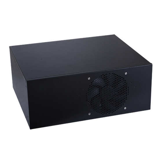
4 LAN ports (for WM343-KD331) 1 COM port 1 x VGA Displays 1 x DVI-D (DVI-I connector) 1 x DP++ Front View 4 USB 3.0 ports + 2 USB 2.0 ports Mic-in and Line-out (for WM343-KD330 only) Audio Rear View Chapter 1 Introduction www.dfi.com... -
Page 6: Chapter 1 - Introduction
4 LAN ports (for WM343-KD331) 1 COM port 1 x VGA Displays 1 x DVI-D (DVI-I connector) 1 x DP++ Front View 4 USB 3.0 ports + 2 USB 2.0 ports Mic-in and Line-out (for WM343-KD330 only) Audio Rear View Chapter 1 Introduction www.dfi.com... - Page 7 Four 288-pin DIMM up to 64GB, Dual Channel DDR4 2133/2400 MHz Intel Core™ i7-6700TE Processor, Quad Core, 8M Cache, ® WM343-KD330 (KD330-Q170) 2.4GHz (3.4GHz), 35W Four 288-pin DIMM up to 64GB, dual channel DDR4 2133/2400 MHz Intel Core™ i5-6500 Processor, Quad Core, 6M Cache, ®...
- Page 7 Four 288-pin DIMM up to 64GB, Dual Channel DDR4 2133/2400 MHz Intel Core™ i7-6700TE Processor, Quad Core, 8M Cache, ® WM343-KD330 (KD330-Q170) 2.4GHz (3.4GHz), 35W Four 288-pin DIMM up to 64GB, dual channel DDR4 2133/2400 MHz Intel Core™ i5-6500 Processor, Quad Core, 6M Cache, ®...
- Page 8 PS/2 1 x PS/2 (mini-DIN-6) Display 1 x VGA 1 x DVI-I (DVI-D signal) 1 x DP++ Audio 1 x Line-out, 1 x Mic-in (WM343-KD330 only) Buttons 1 x Power Button Cooling 1 x System Fan WatchDog Output & System Reset, Programmable via Software from 1 to 255...
- Page 8 PS/2 1 x PS/2 (mini-DIN-6) Display 1 x VGA 1 x DVI-I (DVI-D signal) 1 x DP++ Audio 1 x Line-out, 1 x Mic-in (WM343-KD330 only) Buttons 1 x Power Button Cooling 1 x System Fan WatchDog Output & System Reset, Programmable via Software from 1 to 255...
- Page 9 USB 2�0 Ports Connect USB 2.0 devices and devices based on USB 1.1/1.0 versions. LAN Ports Connect the system to a local area network. Line-out/Mic-in (for WM343-KD330 only) Connects an external speaker and microphone. PS/2 KB/Mouse Connects a PS/2 keyboard and mouse.
- Page 9 USB 2�0 Ports Connect USB 2.0 devices and devices based on USB 1.1/1.0 versions. LAN Ports Connect the system to a local area network. Line-out/Mic-in (for WM343-KD330 only) Connects an external speaker and microphone. PS/2 KB/Mouse Connects a PS/2 keyboard and mouse.
- Page 10 Chapter 1 Mechanical Dimensions (WM343-KD330) Mechanical Dimensions (WM343-KD331) Rear View Rear View Left View Right View Right View Left View Front View Front View Chapter 1 Introduction www.dfi.com...
- Page 10 Chapter 1 Mechanical Dimensions (WM343-KD330) Mechanical Dimensions (WM343-KD331) Rear View Rear View Left View Right View Right View Left View Front View Front View Chapter 1 Introduction www.dfi.com...
- Page 11 Chapter 1 Motherboard Dimensions (KD330-Q170/KD330-H110) Motherboard Dimensions (KD331-C236/KD331-Q170) 10.16 10.16 0.00 0.00 22.86 22.86 29.22 46.94 46.94 75.29 75.29 94.79 94.79 130.79 130.79 150.29 150.29 154.94 154.94 154.94 154.94 205.33 227.33 227.33 233.68 233.68 Chapter 1 Introduction www.dfi.com...
- Page 11 Chapter 1 Motherboard Dimensions (KD330-Q170/KD330-H110) Motherboard Dimensions (KD331-C236/KD331-Q170) 10.16 10.16 0.00 0.00 22.86 22.86 29.22 46.94 46.94 75.29 75.29 94.79 94.79 130.79 130.79 150.29 150.29 154.94 154.94 154.94 154.94 205.33 227.33 227.33 233.68 233.68 Chapter 1 Introduction www.dfi.com...
-
Page 12: Chapter 2 - Getting Started
Please refer to your operating system manual for instructions on installing an operating system. Installing the Drivers The system requires you to install drivers for some devices to operate properly. Refer to the Supported Software chapter for instructions on installing the drivers. Chapter 2 Getting Started www.dfi.com... -
Page 12: Chapter 2 - Getting Started
Installing the Drivers The system package includes a CD disk. The CD includes drivers that must be installed to pro- vide the best system performance. Refer to the Supported Software chapter for instructions on installing the drivers. Chapter 2 Getting Started www.dfi.com... -
Page 13: Chapter 3 - Installing Devices
Make sure the system and all other peripheral devices connected to it have been powered off. Disconnect all power cords and cables. Remove the top cover by uninstalling the thumb screws. Optical drive tray screw Thumb screw Optical drive tray screw Chapter 3 Installing Devices www.dfi.com... -
Page 13: Chapter 3 - Installing Devices
Make sure the system and all other peripheral devices connected to it have been powered off. Disconnect all power cords and cables. Remove the top cover by uninstalling the thumb screws. Optical drive tray screw Thumb screw Optical drive tray screw Chapter 3 Installing Devices www.dfi.com... - Page 14 LGA 1151 socket comes with the protective cap. Load lever Protective 4. Unlock the socket by pushing the load lever down, move it sideways until it is released from the retention tab, and then lift the load lever up. Chapter 3 Installing Devices www.dfi.com...
- Page 14 LGA 1151 socket comes with the protective cap. Load lever Protective 4. Unlock the socket by pushing the load lever down, move it sideways until it is released from the retention tab, and then lift the load lever up. Chapter 3 Installing Devices www.dfi.com...
- Page 15 8. Insert the CPU into the socket. The gold triangular mark on the CPU must align with the corner of the CPU socket as shown below. The CPU’s notch will at the same time fit into the socket’s alignment key. Alignment key Gold triangular mark Chapter 3 Installing Devices www.dfi.com...
- Page 15 8. Insert the CPU into the socket. The gold triangular mark on the CPU must align with the corner of the CPU socket as shown below. The CPU’s notch will at the same time fit into the socket’s alignment key. Alignment key Gold triangular mark Chapter 3 Installing Devices www.dfi.com...
- Page 16 CPU fan connector on tem board, must match the the system board. 4 mounting holes around the socket. 3. Orient the heat sink such that the CPU fan’s cable is nearest the CPU fan con- nector. Chapter 3 Installing Devices www.dfi.com...
- Page 16 CPU fan connector on tem board, must match the the system board. 4 mounting holes around the socket. 3. Orient the heat sink such that the CPU fan’s cable is nearest the CPU fan con- nector. Chapter 3 Installing Devices www.dfi.com...
- Page 17 HDD drive tray. Use 4 mounting screws to install the hard drive onto the HDD drive tray. Mounting screw Mounting screw Drive bay Mounting screw Mounting screw 2�5" SATA Drive 3�5" SATA Drive Chapter 3 Installing Devices www.dfi.com...
- Page 17 HDD drive tray. Use 4 mounting screws to install the hard drive onto the HDD drive tray. Mounting screw Mounting screw Drive bay Mounting screw Mounting screw 2�5" SATA Drive 3�5" SATA Drive Chapter 3 Installing Devices www.dfi.com...
- Page 18 HDD drive tray. Use 4 mounting screws to install the hard drive onto the HDD drive tray. Mounting screw Drive bay Mounting screw Slide the HDD drive tray with the installed hard drive into the optical drive bay and secure the installation with the thumb screws. Chapter 3 Installing Devices www.dfi.com...
- Page 18 HDD drive tray. Use 4 mounting screws to install the hard drive onto the HDD drive tray. Mounting screw Drive bay Mounting screw Slide the HDD drive tray with the installed hard drive into the optical drive bay and secure the installation with the thumb screws. Chapter 3 Installing Devices www.dfi.com...
- Page 19 Secure the hard drive to the optical drive tray. Align the standoffs on the HDD with the mounting holes on the optical drive tray. Use 4 mounting screws to install the hard drive onto the optical drive tray. Mounting screw Mounting screw Chapter 3 Installing Devices www.dfi.com...
- Page 19 Secure the hard drive to the optical drive tray. Align the standoffs on the HDD with the mounting holes on the optical drive tray. Use 4 mounting screws to install the hard drive onto the optical drive tray. Mounting screw Mounting screw Chapter 3 Installing Devices www.dfi.com...
- Page 20 Insert the expansion card in the connector on the motherboard and press down until secured. Notes: The WM343-KD330 is equipped with one PCIe x16, one PCIe x4 and one PCI slots. The WM343-KD331 is equipped with two PCIe x16 and two PCIe x4 slots.
- Page 20 Insert the expansion card in the connector on the motherboard and press down until secured. Notes: The WM343-KD330 is equipped with one PCIe x16, one PCIe x4 and one PCI slots. The WM343-KD331 is equipped with two PCIe x16 and two PCIe x4 slots.
- Page 21 Note: Note: ® The M.2 slot is available in WM343-KD331 (both Intel C236 and Q170 chipsets) and The Mini PCIe slot is available in WM343-KD330 (only Intel ® Q170 Chipset). the SKU with Intel ® C236 chipset further supports Intel ®...
- Page 21 Note: Note: ® The M.2 slot is available in WM343-KD331 (both Intel C236 and Q170 chipsets) and The Mini PCIe slot is available in WM343-KD330 (only Intel ® Q170 Chipset). the SKU with Intel ® C236 chipset further supports Intel ®...
-
Page 22: Chapter 4 - Jumper Settings
Chapter 4 Chapter 4 - Jumper Settings Clear CMOS WM343-KD330 COM 1 (DDR4_2, DDR4_4 for KD330-Q170 only) RS232/422/485 DDR4_2 DDR4_4 Select (JP7) DDR4_1 DDR4_3 PS/2 KB/MS COM 1 RS232/Power Select (JP9) USB 5-6 System Fan 1 CPU Fan USB 2.0... -
Page 22: Chapter 4 - Jumper Settings
Chapter 4 Chapter 4 - Jumper Settings Clear CMOS WM343-KD330 COM 1 (DDR4_2, DDR4_4 for KD330-Q170 only) RS232/422/485 DDR4_2 DDR4_4 Select (JP7) DDR4_1 DDR4_3 PS/2 KB/MS COM 1 RS232/Power Select (JP9) USB 5-6 System Fan 1 CPU Fan USB 2.0... -
Page 23: Serial Port Rs232/422/485 Select
Chapter 4 Serial Port RS232/422/485 Select WM343-KD330 JP7, JP8, and JP10 (for COM 1) and JP11, JP12, and JP13 (for COM 2) are used to configure the COM ports to RS232, RS422 (full duplex) or RS485. The pin assignments of the COM ports will vary according to the jumpers’... -
Page 23: Serial Port Rs232/422/485 Select
Chapter 4 Serial Port RS232/422/485 Select WM343-KD330 JP7, JP8, and JP10 (for COM 1) and JP11, JP12, and JP13 (for COM 2) are used to configure the COM ports to RS232, RS422 (full duplex) or RS485. The pin assignments of the COM ports will vary according to the jumpers’... - Page 24 COM ports to RS232, RS422 (full duplex) or RS485. The pin assignments of the COM ports will RS422 vary according to the jumpers’ settings. RS232 RS485 Full Duplex COM 2 RS422 RS232 Full Duplex RS485 Chapter 4 Jumper Settings www.dfi.com...
- Page 24 COM ports to RS232, RS422 (full duplex) or RS485. The pin assignments of the COM ports will RS422 vary according to the jumpers’ settings. RS232 RS485 Full Duplex COM 2 RS422 RS232 Full Duplex RS485 Chapter 4 Jumper Settings www.dfi.com...
-
Page 25: Serial Port Power Select
Chapter 4 Serial Port Power Select WM343-KD330 JP9 (for COM1) and JP14 (for COM2) are used to switch the COM ports to RS232 or RS232 with power. The pin assignments of the COM ports will vary according to the jumper settings. -
Page 25: Serial Port Power Select
Chapter 4 Serial Port Power Select WM343-KD330 JP9 (for COM1) and JP14 (for COM2) are used to switch the COM ports to RS232 or RS232 with power. The pin assignments of the COM ports will vary according to the jumper settings. -
Page 26: Mini Pcie/Msata Signal Select (For Kd330-Q170 Only)
COM 2 RS232/422/485 Select (JP13) COM 2 RS232/Power Select (JP14) Mini PCIe Socket JP6 is used to select the signal for the Mini PCIe socket. Mini PCIe/mSATA Signal Select Mini PCIe (default) 1-2 On mSATA 2-3 On Chapter 4 Jumper Settings www.dfi.com... -
Page 27: Chapter 5 - Ports And Connectors
Advanced menu (“ACPI Configuration” submenu) of the BIOS. Refer to • One DisplayPort Chapter 7 for more information. • Two RJ45 LAN ports (for WM343-KD330) or four RJ45 LAN ports (for WM343-KD331) • Four USB 3.0 ports • Two USB 2.0 ports •... -
Page 27: Chapter 5 - Ports And Connectors
Advanced menu (“ACPI Configuration” submenu) of the BIOS. Refer to • One DisplayPort Chapter 7 for more information. • Two RJ45 LAN ports (for WM343-KD330) or four RJ45 LAN ports (for WM343-KD331) • Four USB 3.0 ports • Two USB 2.0 ports •... -
Page 28: Com (Serial) Ports
VESA and backwards compatible with VGA, DVI and HDMI, delivers higher performance than any other digital interfaces. BIOS Setting Configure display devices in the advanced menu (“Video Configuration” submenu) of the BIOS. Refer to Chapter 7 for more information. Chapter 5 Ports and Connectors www.dfi.com... -
Page 29: Rj45 Lan Ports
In addition to the external USB ports, the system board is equipped with onboard USB 3.0 and • LAN 1: Intel I219V for WM343-KD330 (with the H110 chipset) ® 2.0 pin headers. Refer to “I/O Connectors” in this chapter for more information. -
Page 29: Rj45 Lan Ports
In addition to the external USB ports, the system board is equipped with onboard USB 3.0 and • LAN 1: Intel I219V for WM343-KD330 (with the H110 chipset) ® 2.0 pin headers. Refer to “I/O Connectors” in this chapter for more information. -
Page 30: Audio
Vertical USB USB 2.0 Rear Audio (for WM343-KD330 only) Front Audio The WM343-KD330 is equipped with 2 audio jacks: The front audio connector allows you to connect the line-out and mic-in jacks for audio output. • Line-out Jack (lime) Driver Installation This jack is used to connect a headphone or external speakers. -
Page 31: S/Pdif Connector
NCT6106D Realtek ALC888S Buzzer SPI Flash (JP13) (JP12) BIOS USB 3.0 COM 5 COM 6 COM 2 COM 3 COM 4 USB 5-6 S/PDIF USB 9-10 USB 7-8 or Optional Vertical USB USB 2.0 Chapter 5 Ports and Connectors www.dfi.com... -
Page 31: S/Pdif Connector
NCT6106D Realtek ALC888S Buzzer SPI Flash (JP13) (JP12) BIOS USB 3.0 COM 5 COM 6 COM 2 COM 3 COM 4 USB 5-6 S/PDIF USB 9-10 USB 7-8 or Optional Vertical USB USB 2.0 Chapter 5 Ports and Connectors www.dfi.com... -
Page 32: Digital I/O And Power Connector
NCT6106D Realtek ALC888S Buzzer SPI Flash (JP13) (JP12) BIOS USB 3.0 COM 5 COM 6 COM 2 COM 3 COM 4 USB 5-6 S/PDIF USB 7-8 USB 9-10 or Optional Vertical USB USB 2.0 Chapter 5 Ports and Connectors www.dfi.com... -
Page 32: Digital I/O And Power Connector
NCT6106D Realtek ALC888S Buzzer SPI Flash (JP13) (JP12) BIOS USB 3.0 COM 5 COM 6 COM 2 COM 3 COM 4 USB 5-6 S/PDIF USB 7-8 USB 9-10 or Optional Vertical USB USB 2.0 Chapter 5 Ports and Connectors www.dfi.com... -
Page 33: Sata (Serial Ata) Connectors
NCT6106D Realtek ALC888S Buzzer SPI Flash (JP13) (JP12) BIOS USB 3.0 COM 2 COM 3 COM 4 COM 5 COM 6 USB 5-6 S/PDIF USB 9-10 USB 7-8 or Optional Vertical USB USB 2.0 Chapter 5 Ports and Connectors www.dfi.com... -
Page 33: Sata (Serial Ata) Connectors
NCT6106D Realtek ALC888S Buzzer SPI Flash (JP13) (JP12) BIOS USB 3.0 COM 2 COM 3 COM 4 COM 5 COM 6 USB 5-6 S/PDIF USB 9-10 USB 7-8 or Optional Vertical USB USB 2.0 Chapter 5 Ports and Connectors www.dfi.com... -
Page 34: Com (Serial) Ports
Configure the serial ports with more advanced options such as the RS485 auto flow mecha- Vertical USB COM 3/4/5/6: RS232 USB 2.0 nism in the Advanced menu (“Super I/O” submenu) of the BIOS. Refer to Chapter 7 for more information. Chapter 5 Ports and Connectors www.dfi.com... -
Page 35: Usb Ports
USB 3.0 your operating system’s documentation for more information. COM 2 COM 3 COM 4 COM 5 COM 6 USB 5-6 S/PDIF USB 9-10 USB 7-8 or Optional Vertical USB USB 2.0 USB 2.0 Chapter 5 Ports and Connectors www.dfi.com... -
Page 35: Usb Ports
USB 3.0 your operating system’s documentation for more information. COM 2 COM 3 COM 4 COM 5 COM 6 USB 5-6 S/PDIF USB 9-10 USB 7-8 or Optional Vertical USB USB 2.0 USB 2.0 Chapter 5 Ports and Connectors www.dfi.com... -
Page 36: Cooling Fan Connectors
Fan 1 Realtek ALC888S Buzzer SPI Flash (JP13) (JP12) BIOS USB 3.0 COM 2 COM 3 COM 4 COM 5 COM 6 USB 5-6 S/PDIF USB 9-10 USB 7-8 or Optional Vertical USB USB 2.0 Chapter 5 Ports and Connectors www.dfi.com... -
Page 36: Cooling Fan Connectors
Fan 1 Realtek ALC888S Buzzer SPI Flash (JP13) (JP12) BIOS USB 3.0 COM 2 COM 3 COM 4 COM 5 COM 6 USB 5-6 S/PDIF USB 9-10 USB 7-8 or Optional Vertical USB USB 2.0 Chapter 5 Ports and Connectors www.dfi.com... -
Page 37: Chassis Intrusion Connector
NCT6106D Realtek ALC888S Buzzer SPI Flash (JP13) (JP12) BIOS USB 3.0 COM 5 COM 6 COM 2 COM 3 COM 4 USB 5-6 S/PDIF USB 7-8 USB 9-10 or Optional Vertical USB USB 2.0 Chapter 5 Ports and Connectors www.dfi.com... -
Page 37: Chassis Intrusion Connector
NCT6106D Realtek ALC888S Buzzer SPI Flash (JP13) (JP12) BIOS USB 3.0 COM 5 COM 6 COM 2 COM 3 COM 4 USB 5-6 S/PDIF USB 7-8 USB 9-10 or Optional Vertical USB USB 2.0 Chapter 5 Ports and Connectors www.dfi.com... -
Page 38: Lpc Connector
NCT6106D Realtek ALC888S Buzzer SPI Flash (JP13) (JP12) BIOS USB 3.0 COM 5 COM 6 COM 2 COM 3 COM 4 USB 5-6 S/PDIF USB 9-10 USB 7-8 or Optional Vertical USB USB 2.0 Chapter 5 Ports and Connectors www.dfi.com... -
Page 38: Lpc Connector
NCT6106D Realtek ALC888S Buzzer SPI Flash (JP13) (JP12) BIOS USB 3.0 COM 5 COM 6 COM 2 COM 3 COM 4 USB 5-6 S/PDIF USB 9-10 USB 7-8 or Optional Vertical USB USB 2.0 Chapter 5 Ports and Connectors www.dfi.com... -
Page 39: Power Connectors
Fan 1 Realtek ALC888S Buzzer SPI Flash (JP13) (JP12) BIOS USB 3.0 COM 2 COM 3 COM 4 COM 5 COM 6 USB 5-6 S/PDIF USB 9-10 USB 7-8 or Optional Vertical USB USB 2.0 Chapter 5 Ports and Connectors www.dfi.com... -
Page 39: Power Connectors
Fan 1 Realtek ALC888S Buzzer SPI Flash (JP13) (JP12) BIOS USB 3.0 COM 2 COM 3 COM 4 COM 5 COM 6 USB 5-6 S/PDIF USB 9-10 USB 7-8 or Optional Vertical USB USB 2.0 Chapter 5 Ports and Connectors www.dfi.com... -
Page 40: Smbus Connector
NCT6106D Realtek ALC888S Buzzer SPI Flash (JP13) (JP12) BIOS USB 3.0 COM 2 COM 3 COM 4 COM 5 COM 6 USB 5-6 S/PDIF USB 9-10 USB 7-8 or Optional Vertical USB USB 2.0 Chapter 5 Ports and Connectors www.dfi.com... -
Page 40: Smbus Connector
NCT6106D Realtek ALC888S Buzzer SPI Flash (JP13) (JP12) BIOS USB 3.0 COM 2 COM 3 COM 4 COM 5 COM 6 USB 5-6 S/PDIF USB 9-10 USB 7-8 or Optional Vertical USB USB 2.0 Chapter 5 Ports and Connectors www.dfi.com... -
Page 41: Front Panel Connector
NCT6106D Realtek ALC888S Buzzer SPI Flash (JP13) (JP12) BIOS USB 3.0 COM 2 COM 3 COM 4 COM 5 COM 6 USB 5-6 S/PDIF USB 9-10 USB 7-8 or Optional Vertical USB USB 2.0 Chapter 5 Ports and Connectors www.dfi.com... -
Page 41: Front Panel Connector
NCT6106D Realtek ALC888S Buzzer SPI Flash (JP13) (JP12) BIOS USB 3.0 COM 2 COM 3 COM 4 COM 5 COM 6 USB 5-6 S/PDIF USB 9-10 USB 7-8 or Optional Vertical USB USB 2.0 Chapter 5 Ports and Connectors www.dfi.com... -
Page 42: Expansion Slots
Configure these PCIe slots including their speed in the Advanced menu (“PCI Express Configu- S/PDIF USB 7-8 USB 9-10 or Optional ration” submenu) of the BIOS. Refer to Chapter 7 for more information. Vertical USB USB 2.0 Chapter 5 Ports and Connectors www.dfi.com... -
Page 42: Expansion Slots
Configure these PCIe slots including their speed in the Advanced menu (“PCI Express Configu- S/PDIF USB 7-8 USB 9-10 or Optional ration” submenu) of the BIOS. Refer to Chapter 7 for more information. Vertical USB USB 2.0 Chapter 5 Ports and Connectors www.dfi.com... -
Page 43: Standby Power Led
Failure to do so will cause severe damage to the motherboard and components. Safety Measures • Danger of explosion if battery incorrectly replaced. • Replace only with the same or equivalent type recommend by the manufacturer. • Dispose of used batteries according to local ordinance. Chapter 5 Ports and Connectors www.dfi.com... -
Page 44: Lan Led
The pin functions of the LAN LED con- nector are listed below. Pin Assignment Pin Assignment GBE_LED_1000- GBE_LED_100- GBE_LED_LINK_ACT- 3V3DU LINK_1000_2 LINK_100_2 LINK_ACTIVITY_2 3V3DU Chapter 5 Ports and Connectors www.dfi.com... -
Page 44: Lan Led
The pin functions of the LAN LED con- nector are listed below. Pin Assignment Pin Assignment GBE_LED_1000- GBE_LED_100- GBE_LED_LINK_ACT- 3V3DU LINK_1000_2 LINK_100_2 LINK_ACTIVITY_2 3V3DU Chapter 5 Ports and Connectors www.dfi.com... -
Page 45: Chapter 6 - Mounting Options
2 wall mount brackets Ø4.60 1. On the bottom of the system, use 4 mounting screws to secure the wall mount brackets on each side of the system. Ø3.60 Mounting screw Mounting screw Mounting screw Mounting screw Chapter 6 Mounting Options www.dfi.com... -
Page 45: Chapter 6 - Mounting Options
2 wall mount brackets Ø4.60 1. On the bottom of the system, use 4 mounting screws to secure the wall mount brackets on each side of the system. Ø3.60 Mounting screw Mounting screw Mounting screw Mounting screw Chapter 6 Mounting Options www.dfi.com... - Page 46 2 Rack-mount tray brackets 1. Place the system on the rack-mount tray and align the mounting holes of the tray with the mount bracket. 2. Follow the rack manufacture's instruction to properly secure the system to the rack. Chapter 6 Mounting Options www.dfi.com...
- Page 46 2 Rack-mount tray brackets 1. Place the system on the rack-mount tray and align the mounting holes of the tray with the mount bracket. 2. Follow the rack manufacture's instruction to properly secure the system to the rack. Chapter 6 Mounting Options www.dfi.com...
-
Page 47: Chapter 7 - Bios Setup
“Press DEL to run setup” will appear on the screen. If the message that field and press <Enter>. disappears before you respond, restart the system or press the “Reset” button. You may also restart the system by pressing the <Ctrl> <Alt> and <Del> keys simultaneously. Chapter 7 BIOS Setup www.dfi.com... -
Page 48: Insyde Bios Setup Utility
Minute displays minutes from 00 to 59. Second displays seconds from 00 to 59. System Date The date format is <month>, <date>, <year>. Month displays the month, from January to December. Date displays the date, from 1 to 31. Year displays the year, from 1980 to 2099. Chapter 7 BIOS Setup www.dfi.com... -
Page 48: Insyde Bios Setup Utility
Minute displays minutes from 00 to 59. Second displays seconds from 00 to 59. System Date The date format is <month>, <date>, <year>. Month displays the month, from January to December. Date displays the date, from 1 to 31. Year displays the year, from 1980 to 2099. Chapter 7 BIOS Setup www.dfi.com... - Page 49 <minute>, <second>. The default is disabled. of operating systems and software that are optimized for hyper-threading technology. Please check the software specifications to determine if enabling HT can be advantageous to the overall system performance. Chapter 7 BIOS Setup www.dfi.com...
- Page 49 <minute>, <second>. The default is disabled. of operating systems and software that are optimized for hyper-threading technology. Please check the software specifications to determine if enabling HT can be advantageous to the overall system performance. Chapter 7 BIOS Setup www.dfi.com...
- Page 50 PEG: PEG (PCIe Graphics devices connected to PEG lanes directly routed from the CPU) ->PCIe graphics devices->PCI graphics devices->IGFX (internal graphics) PCIe: PCIe graphics devices->PEG (PCIe Graphics devices connected to PEG lanes directly routed from the CPU )->IGFX (internal graphics)->PCI graphics devices Chapter 7 BIOS Setup www.dfi.com...
- Page 50 PEG: PEG (PCIe Graphics devices connected to PEG lanes directly routed from the CPU) ->PCIe graphics devices->PCI graphics devices->IGFX (internal graphics) PCIe: PCIe graphics devices->PEG (PCIe Graphics devices connected to PEG lanes directly routed from the CPU )->IGFX (internal graphics)->PCI graphics devices Chapter 7 BIOS Setup www.dfi.com...
- Page 51 Control the detection of the high-definition audio devices. Disabled High-definition audio devices will be unconditionally disabled. Enabled High-definition audio devices will be unconditionally enabled. Auto High-definition audio devices will be enabled if present and disabled otherwise. Chapter 7 BIOS Setup www.dfi.com...
- Page 51 Control the detection of the high-definition audio devices. Disabled High-definition audio devices will be unconditionally disabled. Enabled High-definition audio devices will be unconditionally enabled. Auto High-definition audio devices will be enabled if present and disabled otherwise. Chapter 7 BIOS Setup www.dfi.com...
- Page 52 Enable or disable each Serial ATA port and its hot plug function. SATA Port 5 controls the signal of the M.2 slot. Note that for WM343-KD330 (KD330-H110), the SATA port will be numbered from 0 to 3. And for WM343-KD330 (KD330-Q170), it will be numbered from 0 to 4 (port 4 controls the signal of the Mini PCIe slot).
- Page 52 Enable or disable each Serial ATA port and its hot plug function. SATA Port 5 controls the signal of the M.2 slot. Note that for WM343-KD330 (KD330-H110), the SATA port will be numbered from 0 to 3. And for WM343-KD330 (KD330-Q170), it will be numbered from 0 to 4 (port 4 controls the signal of the Mini PCIe slot).
- Page 53 PCIE 4: PCIE4 slot (Note this is only available for KD331-C236/Q170) Enable or disable the hot plug function of the PCIe root port. LAN 1~LAN 4 LAN 3 and LAN 4 are only available for WM343-KD331. Chapter 7 BIOS Setup www.dfi.com...
- Page 53 PCIE 4: PCIE4 slot (Note this is only available for KD331-C236/Q170) Enable or disable the hot plug function of the PCIe root port. LAN 1~LAN 4 LAN 3 and LAN 4 are only available for WM343-KD331. Chapter 7 BIOS Setup www.dfi.com...
- Page 54 Management Engine firmware flashing when updating the BIOS. ® Intel AMT Support Enable or disable Intel Active Management Technology BIOS extension. ® Un-Configure ME Clears all ME related configurations without requiring a password on the next boot. Chapter 7 BIOS Setup www.dfi.com...
- Page 54 Management Engine firmware flashing when updating the BIOS. ® Intel AMT Support Enable or disable Intel Active Management Technology BIOS extension. ® Un-Configure ME Clears all ME related configurations without requiring a password on the next boot. Chapter 7 BIOS Setup www.dfi.com...
-
Page 55: Uefi Device Manager
BIOS setup utility. you can select either the IPv4 or IPv6 network settings for UEFI network configuration. NIC Configuration Menu This screen shows hardware information for the Ethernet controllers and configures their operation. Chapter 7 BIOS Setup www.dfi.com... -
Page 55: Uefi Device Manager
BIOS setup utility. you can select either the IPv4 or IPv6 network settings for UEFI network configuration. NIC Configuration Menu This screen shows hardware information for the Ethernet controllers and configures their operation. Chapter 7 BIOS Setup www.dfi.com... - Page 56 . x . x . x (x must be a decimal value between 0 and 255). Local Gateway: Enter the gateway address in the IPv4 format. Local DNS (Domain Name System) Servers: Enter DNS (Domain Name System) server IP addresses in the IPv4 format. Chapter 7 BIOS Setup www.dfi.com...
- Page 56 . x . x . x (x must be a decimal value between 0 and 255). Local Gateway: Enter the gateway address in the IPv4 format. Local DNS (Domain Name System) Servers: Enter DNS (Domain Name System) server IP addresses in the IPv4 format. Chapter 7 BIOS Setup www.dfi.com...
- Page 57 The range of the temperature is from 0 to 127 Case Open Fan Speed Count 1 to Fan Speed Count 4 Enable or disable the case open function. Set the fan speed. The range is from 1 (lowest speed)-100% (full speed). Chapter 7 BIOS Setup www.dfi.com...
- Page 57 The range of the temperature is from 0 to 127 Case Open Fan Speed Count 1 to Fan Speed Count 4 Enable or disable the case open function. Set the fan speed. The range is from 1 (lowest speed)-100% (full speed). Chapter 7 BIOS Setup www.dfi.com...
- Page 58 Chapter 7 PC Health Status This section displays PC health information such as the voltages and CPU and system temperatures. Chapter 7 BIOS Setup www.dfi.com...
- Page 58 Chapter 7 PC Health Status This section displays PC health information such as the voltages and CPU and system temperatures. Chapter 7 BIOS Setup www.dfi.com...
- Page 59 Parity: None, Even or Odd. Stop bits: 1 bit or 2 bits. Flow control: None, RTS/CTS or XON/XOFF This is the global setting for all of the designated serial ports for the console redirection function. Chapter 7 BIOS Setup www.dfi.com...
- Page 59 Parity: None, Even or Odd. Stop bits: 1 bit or 2 bits. Flow control: None, RTS/CTS or XON/XOFF This is the global setting for all of the designated serial ports for the console redirection function. Chapter 7 BIOS Setup www.dfi.com...
-
Page 60: Security
If you select to set the supervisor password, this option will be shown. Enable or disable • Disable: Disable and deactivate TPM. prompt for password at boot. • Enable: Enable and activate TPM. Clear TPM Remove all TPM ownership contents. Chapter 7 BIOS Setup www.dfi.com... -
Page 60: Security
If you select to set the supervisor password, this option will be shown. Enable or disable • Disable: Disable and deactivate TPM. prompt for password at boot. • Enable: Enable and activate TPM. Clear TPM Remove all TPM ownership contents. Chapter 7 BIOS Setup www.dfi.com... -
Page 61: Boot
Enable or disable the quiet boot function to configure the screen’s display between POST messages or the OEM logo at bootup. Select Disabled to display the POST messages and select Enabled to display the OEM logo. Chapter 7 BIOS Setup www.dfi.com... -
Page 61: Boot
Enable or disable the quiet boot function to configure the screen’s display between POST messages or the OEM logo at bootup. Select Disabled to display the POST messages and select Enabled to display the OEM logo. Chapter 7 BIOS Setup www.dfi.com... -
Page 62: Exit
DSF file extension and can be used for restoration. Restore Setting from file Select this option to restore BIOS configuration settings from a USB drive. Note that this option appears only if a USB device is detected on the system. Chapter 7 BIOS Setup www.dfi.com... -
Page 62: Exit
DSF file extension and can be used for restoration. Restore Setting from file Select this option to restore BIOS configuration settings from a USB drive. Note that this option appears only if a USB device is detected on the system. Chapter 7 BIOS Setup www.dfi.com... -
Page 63: Updating The Bios
MAC address should be burned Initializing Current BIOS Model name: KD330 or not. New BIOS Model name: KD330 Current BIOS version: B17A.31A New BIOS version: B18A.31A Updating Block at FFFFF000h 100% 100% C:\KD330>_ Chapter 7 BIOS Setup www.dfi.com... -
Page 63: Updating The Bios
MAC address should be burned Initializing Current BIOS Model name: KD330 or not. New BIOS Model name: KD330 Current BIOS version: B17A.31A New BIOS version: B18A.31A Updating Block at FFFFF000h 100% 100% C:\KD330>_ Chapter 7 BIOS Setup www.dfi.com... -
Page 64: Chapter 8 - Supported Software
Chapter 8 - Supported Software The system requires you to install drivers for some devices to operate properly. To download the latest driver, please go to the DFI Download Center: http://www.dfi.com/DownloadCenter Once you are in the Download Center page, select your product or type the model name and click "Search"... -
Page 64: Chapter 8 - Supported Software
Chapter 8 - Supported Software The system requires you to install drivers for some devices to operate properly. To download the latest driver, please go to the DFI Download Center: http://www.dfi.com/DownloadCenter Once you are in the Download Center page, select your product or type the model name and click "Search"... - Page 65 Click “Next”. 4. Please wait while the instal- lation is in progress. 2. Read the license agreement, and then click “Yes”. 5. Click “Restart Now” to allow the new software installa- tion to take effect. Chapter 8 Supported Software www.dfi.com...
- Page 65 Click “Next”. 4. Please wait while the instal- lation is in progress. 2. Read the license agreement, and then click “Yes”. 5. Click “Restart Now” to allow the new software installa- tion to take effect. Chapter 8 Supported Software www.dfi.com...
- Page 66 2. Read the license agree- 5. Click “Yes, I want to restart ment, and then click “Yes”. this computer now”, and then click “Finish”. Restarting the system will allow the new software installation to take effect. Chapter 8 Supported Software www.dfi.com...
- Page 66 2. Read the license agree- 5. Click “Yes, I want to restart ment, and then click “Yes”. this computer now”, and then click “Finish”. Restarting the system will allow the new software installation to take effect. Chapter 8 Supported Software www.dfi.com...
- Page 67 “Finish”. 2. Click “I accept the terms in the license agreement” if you accept the agreement, and then click “Next”. 3. Select the program features you want to install, and then click “Next”. Chapter 8 Supported Software www.dfi.com...
- Page 67 “Finish”. 2. Click “I accept the terms in the license agreement” if you accept the agreement, and then click “Next”. 3. Select the program features you want to install, and then click “Next”. Chapter 8 Supported Software www.dfi.com...
- Page 68 1. You are about to install the driver. Click “Next” to continue. 4. Please wait while the prod- uct is being installed. 2. Read the license agree- ment, and then click “Next”. 5. After the installation is complete, click “Finish”. Chapter 8 Supported Software www.dfi.com...
- Page 68 1. You are about to install the driver. Click “Next” to continue. 4. Please wait while the prod- uct is being installed. 2. Read the license agree- ment, and then click “Next”. 5. After the installation is complete, click “Finish”. Chapter 8 Supported Software www.dfi.com...
- Page 69 “Finish”. Click “I accept the terms in the License Agreement” if you agree with Restart the system to allow the new the terms in the agreement and then software installation to take effect. click “Next”. Chapter 8 Supported Software www.dfi.com...
- Page 69 “Finish”. Click “I accept the terms in the License Agreement” if you agree with Restart the system to allow the new the terms in the agreement and then software installation to take effect. click “Next”. Chapter 8 Supported Software www.dfi.com...
- Page 70 5. Setup is now installing the driver. 3. Read the file information and then click “Next”. 4. Setup is ready to install the driver. 6. Click “Finish” to exit the setup. Click “Next” to begin the installation. Chapter 8 Supported Software www.dfi.com...
- Page 70 5. Setup is now installing the driver. 3. Read the file information and then click “Next”. 4. Setup is ready to install the driver. 6. Click “Finish” to exit the setup. Click “Next” to begin the installation. Chapter 8 Supported Software www.dfi.com...
- Page 71 SATA drives. It enables enhanced performance and power management for the storage subsystem. You can also install and set up Intel Optane™ memory with the Intel ® ® Rapid Storage Technology application. Please refer to Chapter 9 for more information. Chapter 8 Supported Software www.dfi.com...
- Page 71 SATA drives. It enables enhanced performance and power management for the storage subsystem. You can also install and set up Intel Optane™ memory with the Intel ® ® Rapid Storage Technology application. Please refer to Chapter 9 for more information. Chapter 8 Supported Software www.dfi.com...
-
Page 72: Chapter 9 - Raid
Disk mirroring 5. Reboot the system. Block-level data striping with RAID 5 Single Drive Failure distributed parity 1 Disk Per Mirrored Combination of RAID 0 (data striping) RAID 10 Stripe (not same mirror) and RAID 1 (mirroring) Chapter 9 RAID www.dfi.com... -
Page 72: Chapter 9 - Raid
Disk mirroring 5. Reboot the system. Block-level data striping with RAID 5 Single Drive Failure distributed parity 1 Disk Per Mirrored Combination of RAID 0 (data striping) RAID 10 Stripe (not same mirror) and RAID 1 (mirroring) Chapter 9 RAID www.dfi.com... - Page 73 Select “OK” to continue. These steps are cited from the Intel Support site, “Set Up a System with Intel ® ® 3. The “Intel Rapid Storage Technology” menu appears. Enter this menu. Matrix RAID Technology” (Article ID: 000005789). ® Chapter 9 RAID www.dfi.com...
- Page 73 Select “OK” to continue. These steps are cited from the Intel Support site, “Set Up a System with Intel ® ® 3. The “Intel Rapid Storage Technology” menu appears. Enter this menu. Matrix RAID Technology” (Article ID: 000005789). ® Chapter 9 RAID www.dfi.com...
- Page 74 3. Setup is ready to install the utility. Click “Next” to continue. 4. Read the license agree- ment and click “I accept the terms in the License Agreement“ if you accept the agreement. Then, click “Next”. Chapter 9 RAID www.dfi.com...
- Page 74 3. Setup is ready to install the utility. Click “Next” to continue. 4. Read the license agree- ment and click “I accept the terms in the License Agreement“ if you accept the agreement. Then, click “Next”. Chapter 9 RAID www.dfi.com...
- Page 75 “Finish”. “Next”. 6. Click “Next” to install to the default folder or click “change” to choose another destination folder. 7. Confirm the installation and click “Next”. Chapter 9 RAID www.dfi.com...
- Page 75 “Finish”. “Next”. 6. Click “Next” to install to the default folder or click “change” to choose another destination folder. 7. Confirm the installation and click “Next”. Chapter 9 RAID www.dfi.com...
-
Page 76: Chapter 10 - Intel Amt Settings
It protects the network from threats at the source by proactively blocking incoming threats, reactively containing infected clients before they impact the network, and proactively alerting when critical software agents are removed. 3. In the “Active Management Technology Support” menu, select “Enabled” for “Intel AMT Support”. Chapter 10 Intel AMT Settings www.dfi.com... -
Page 76: Chapter 10 - Intel Amt Settings
It protects the network from threats at the source by proactively blocking incoming threats, reactively containing infected clients before they impact the network, and proactively alerting when critical software agents are removed. 3. In the “Active Management Technology Support” menu, select “Enabled” for “Intel AMT Support”. Chapter 10 Intel AMT Settings www.dfi.com... - Page 77 Copyright(C) 2003-16 Intel Corporation. All Rights Reserved MAIN MENU MEBx Login > Intel (R) ME General Settings > Intel (R) AMT Configuration MEBx Exit Intel(R) ME Password [↑↓] = Move Highlight [Enter] = Select Entry [Esc]= Exit Chapter 10 Intel AMT Settings www.dfi.com...
- Page 77 Copyright(C) 2003-16 Intel Corporation. All Rights Reserved MAIN MENU MEBx Login > Intel (R) ME General Settings > Intel (R) AMT Configuration MEBx Exit Intel(R) ME Password [↑↓] = Move Highlight [Enter] = Select Entry [Esc]= Exit Chapter 10 Intel AMT Settings www.dfi.com...
- Page 78 Intel(R) Management Engine BIOS Extension v11.0.0.0010/Intel(R) ME v11.8.50.3399 Copyright(C) 2003-16 Intel Corporation. All Rights Reserved MAIN MENU > Intel (R) ME General Settings > Intel (R) AMT Configuration MEBx Exit [↑↓] = Move Highlight [Enter] = Select Entry [Esc]= Exit Chapter 10 Intel AMT Settings www.dfi.com...
- Page 78 Intel(R) Management Engine BIOS Extension v11.0.0.0010/Intel(R) ME v11.8.50.3399 Copyright(C) 2003-16 Intel Corporation. All Rights Reserved MAIN MENU > Intel (R) ME General Settings > Intel (R) AMT Configuration MEBx Exit [↑↓] = Move Highlight [Enter] = Select Entry [Esc]= Exit Chapter 10 Intel AMT Settings www.dfi.com...
- Page 79 [Enter] = Select Entry [Esc]= Exit Copyright(C) 2003-16 Intel Corporation. All Rights Reserved MAIN MENU > Intel(R) ME General Settings > Intel(R) AMT Configuration MEBx Exit [↑↓] =Move Highlight [Enter] =Select Entry [Esc] =Exit Chapter 10 Intel AMT Settings www.dfi.com...
- Page 79 [Enter] = Select Entry [Esc]= Exit Copyright(C) 2003-16 Intel Corporation. All Rights Reserved MAIN MENU > Intel(R) ME General Settings > Intel(R) AMT Configuration MEBx Exit [↑↓] =Move Highlight [Enter] =Select Entry [Esc] =Exit Chapter 10 Intel AMT Settings www.dfi.com...
- Page 80 Unconfigure Network Access <Full Unprovision> Disabled > Remote Setup And Configuration Enabled > Power Control [↑↓] = Move Highlight [Enter] = Select Entry [Esc]= Exit [↑↓] = Move Highlight [Enter] = Complete Entry [Esc]= Discard Changes Chapter 10 Intel AMT Settings www.dfi.com...
- Page 80 Unconfigure Network Access <Full Unprovision> Disabled > Remote Setup And Configuration Enabled > Power Control [↑↓] = Move Highlight [Enter] = Select Entry [Esc]= Exit [↑↓] = Move Highlight [Enter] = Complete Entry [Esc]= Discard Changes Chapter 10 Intel AMT Settings www.dfi.com...
- Page 81 < Enabled> Storage Redirection <Enabled> KVM Feature Selection <Enabled> NONE Disabled Enabled [↑↓] = Move Highlight [Enter] = Complete Entry [Esc]= Discard Changes [↑↓] = Move Highlight [Enter] = Complete Entry [Esc]= Discard Changes Chapter 10 Intel AMT Settings www.dfi.com...
- Page 81 < Enabled> Storage Redirection <Enabled> KVM Feature Selection <Enabled> NONE Disabled Enabled [↑↓] = Move Highlight [Enter] = Complete Entry [Esc]= Discard Changes [↑↓] = Move Highlight [Enter] = Complete Entry [Esc]= Discard Changes Chapter 10 Intel AMT Settings www.dfi.com...
- Page 82 <Full Unprovision> > Remote Setup And Configuration > Power Control Default Password Only During Setup And Configuration Anytime [↑↓] =Move Highlight [Enter] =Select Entry [Esc] =Exit [↑↓] =Move Highlight <Enter> =Complete Entry [Esc] =Discard Changes Chapter 10 Intel AMT Settings www.dfi.com...
- Page 82 <Full Unprovision> > Remote Setup And Configuration > Power Control Default Password Only During Setup And Configuration Anytime [↑↓] =Move Highlight [Enter] =Select Entry [Esc] =Exit [↑↓] =Move Highlight <Enter> =Complete Entry [Esc] =Discard Changes Chapter 10 Intel AMT Settings www.dfi.com...
- Page 83 <Shared> Dynamic DNS Update <Disabled> Dynamic DNS Update <Disabled> Computer Domain Name Disabled Enabled [↑↓] =Move Highlight <Enter> =Complete Entry [Esc] =Discard Changes [↑↓] = Move Highlight [Enter] = Complete Entry [Esc]= Discard Changes Chapter 10 Intel AMT Settings www.dfi.com...
- Page 83 <Shared> Dynamic DNS Update <Disabled> Dynamic DNS Update <Disabled> Computer Domain Name Disabled Enabled [↑↓] =Move Highlight <Enter> =Complete Entry [Esc] =Discard Changes [↑↓] = Move Highlight [Enter] = Complete Entry [Esc]= Discard Changes Chapter 10 Intel AMT Settings www.dfi.com...
- Page 84 Unconfigure Network Access <Full Unprovision> Enabled > Remote Setup And Configuration > Power Control Full Unprovision [↑↓] =Move Highlight <Enter> =Complete Entry [Esc] =Discard Changes [↑↓] =Move Highlight <Enter> =Complete Entry [Esc] =Discard Changes Chapter 10 Intel AMT Settings www.dfi.com...
- Page 84 Unconfigure Network Access <Full Unprovision> Enabled > Remote Setup And Configuration > Power Control Full Unprovision [↑↓] =Move Highlight <Enter> =Complete Entry [Esc] =Discard Changes [↑↓] =Move Highlight <Enter> =Complete Entry [Esc] =Discard Changes Chapter 10 Intel AMT Settings www.dfi.com...
- Page 85 Provisioning Server FQDN > TLS PKI > RCFG > TLS PKI Provisioning server address Provisioning Mode: PKI [↑↓] = Move Highlight [Enter] = Select Entry [Esc]= Exit [↑↓] =Move Highlight [Enter] =Select Entry [Esc] =Exit Chapter 10 Intel AMT Settings www.dfi.com...
- Page 85 Provisioning Server FQDN > TLS PKI > RCFG > TLS PKI Provisioning server address Provisioning Mode: PKI [↑↓] = Move Highlight [Enter] = Select Entry [Esc]= Exit [↑↓] =Move Highlight [Enter] =Select Entry [Esc] =Exit Chapter 10 Intel AMT Settings www.dfi.com...
- Page 86 PKI DNS Suffix > Manage Hashes This will activate Remote Configura- Disabled tion. Continue: (Y/N) Enabled [↑↓] = Move Highlight [Enter] = Select Entry [Esc]= Exit [↑↓] =Move Highlight [Enter] =Select Entry [Esc] =Exit Chapter 10 Intel AMT Settings www.dfi.com...
- Page 86 PKI DNS Suffix > Manage Hashes This will activate Remote Configura- Disabled tion. Continue: (Y/N) Enabled [↑↓] = Move Highlight [Enter] = Select Entry [Esc]= Exit [↑↓] =Move Highlight [Enter] =Select Entry [Esc] =Exit Chapter 10 Intel AMT Settings www.dfi.com...
- Page 87 > Network Setup Activate Network Access Unconfigure Network Access <Full Unprovision> > Remote Setup And Configuration > Power Control [↑↓] =Move Highlight [Enter] =Select Entry [Esc] =Exit [↑↓] =Move Highlight [Enter] =Select Entry [Esc] =Exit Chapter 10 Intel AMT Settings www.dfi.com...
- Page 87 > Network Setup Activate Network Access Unconfigure Network Access <Full Unprovision> > Remote Setup And Configuration > Power Control [↑↓] =Move Highlight [Enter] =Select Entry [Esc] =Exit [↑↓] =Move Highlight [Enter] =Select Entry [Esc] =Exit Chapter 10 Intel AMT Settings www.dfi.com...
- Page 88 Intel (R) ME ON in Host Sleep States <Mobile: ON in S0, ME Wake in S3, S4-5 (AC only)> Idle Timeout 65535 Timeout Value (1-65535) 65535 [↑↓] =Move Highlight <Enter> =Complete Entry [Esc] =Discard Changes Chapter 10 Intel AMT Settings www.dfi.com...
- Page 88 Intel (R) ME ON in Host Sleep States <Mobile: ON in S0, ME Wake in S3, S4-5 (AC only)> Idle Timeout 65535 Timeout Value (1-65535) 65535 [↑↓] =Move Highlight <Enter> =Complete Entry [Esc] =Discard Changes Chapter 10 Intel AMT Settings www.dfi.com...
Need help?
Do you have a question about the WM343-KD330 and is the answer not in the manual?
Questions and answers