Table of Contents
Advertisement
Quick Links
Advertisement
Table of Contents

Related Manuals for DFI WM342-KD330


Summary of Contents for DFI WM342-KD330
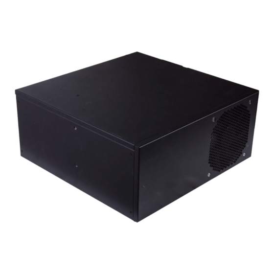
- Page 1 WM342-KD330/KD331 Desktop Box PC User’s Manual A51400907 Chapter 1 Introduction...
-
Page 2: Copyright
FCC and DOC Statement on Class A Copyright This publication contains information that is protected by copyright. No part of it may be re- This equipment has been tested and found to comply with the limits for a Class A digital produced in any form or by any means or used to make any transformation/adaptation without device, pursuant to Part 15 of the FCC rules. -
Page 3: Table Of Contents
Table of Contents Copyright..............2 SATA (Serial ATA) Connectors..............31 COM (Serial) Ports ..................32 Trademarks ..............2 USB Ports....................33 Cooling Fan Connectors................34 FCC and DOC Statement on Class A ......2 Chassis Intrusion Connector ............... 35 LPC Connector.................... 36 About this Manual ............ -
Page 4: About This Manual
About this Manual Static Electricity Precautions An electronic file of this manual is included in the CD. To view the user’s manual in the CD, It is quite easy to inadvertently damage your PC, system board, components or devices even insert the CD into a CD-ROM drive. -
Page 5: Safety Precautions
• Unplug the power cord before removing the system chassis cover for installation or servic- ing. After installation or servicing, cover the system chassis before plugging the power cord. • 1 WM342-KD330 or WM342-KD331 System Unit • 1 CPU cooler •... -
Page 6: Chapter 1 - Introduction
4 LAN ports (for WM342-KD331) 1 COM port 1 x VGA 1 x DVI-D (DVI-I connector) Displays 1 x DP++ 4 USB 3.0 ports + 2 USB 2.0 ports Front View Mic-in and Line-out (for WM342-KD330 only) Audio Rear View Chapter 1 Introduction... - Page 7 Intel Core™ i7-6700 Processor, Quad Core, 8M Cache, ® 3.4GHz (4.0GHz), 65W Four 288-pin DIMM up to 64GB, Dual Channel DDR4 2133/2400 MHz WM342-KD330 (KD330-Q170) Intel Core™ i7-6700TE Processor, Quad Core, 8M Cache, ® 2.4GHz (3.4GHz), 35W Four 288-pin DIMM up to 64GB, dual channel DDR4 2133/2400 MHz...
- Page 8 1 x PS/2 (mini-DIN-6) Display 1 x VGA 1 x DVI-D (DVI-I connector) 1 x DP++ Audio 1 x Line-out, 1 x Mic-in (WM342-KD330 only) Buttons 1 x Power Button, 1 x Reset Button Cooling 1 x System Fan WatchDog Output &...
- Page 9 Connect the system to a local area network. Note that the model with the KD330 mainboard has only two ports whereas the model with the KD331 mainboard has four ports. Line-out/Mic-in (for WM342-KD330 only) Connects an external speaker and microphone.
- Page 10 Chapter 1 Mechanical Dimensions (WM342-KD330) Mechanical Dimensions (WM342-KD331) Rear View Rear View 188.00 59.30 188.00 59.30 Right View Left View 306.60 Right View Left View 306.60 Front View Front View Chapter 1 Introduction...
- Page 11 Chapter 1 Motherboard Dimensions (KD330-Q170/KD330-H110) Motherboard Dimensions (KD331-C236/KD331-Q170) 10.16 10.16 0.00 0.00 22.86 22.86 29.22 46.94 46.94 75.29 75.29 94.79 94.79 130.79 130.79 150.29 150.29 154.94 154.94 154.94 154.94 205.33 227.33 227.33 233.68 233.68 Chapter 1 Introduction...
-
Page 12: Chapter 2 - Getting Started
Chapter 2 Chapter 2 - Getting Started Preparing the System Before you start using the system, you need the following items: • SATA HDD/SSD • M.2 card • PCIe cards • Installing Devices The following devices can be installed in the system: •... -
Page 13: Chapter 3 - Installing Devices
Channel B: DDR4_2 & DDR4_4 The DIMM sockets can only accommodate DDR4 memory modules. Please do not install other types of memory modules. ® The WM342-KD330 (with the Intel H110 Chipset) is equipped with only two DIMM sockets. Chapter 3 Installing Devices... - Page 14 Insert the expansion card in the connector on the motherboard and press it down until secured. Notes: The WM342-KD330 chassis slot can accommodate one PCIe x16 and one PCI slots. The WM342-KD331 chassis slot can accommodate one PCIe x16 and one PCIe x4 slots.
- Page 15 The M.2 slot is available in WM342-KD331 (with both Intel ® C236 and Q170 chipsets) ® The Mini PCIe slot is available in WM342-KD330 (only with Intel Q170 Chipset). and the SKU with Intel ® C236 chipset further supports Intel ®...
- Page 16 Chapter 3 Installing a 2.5” SATA Drive The system can accommodate two 2.5" SATA drives. Use the following procedure to install a SATA drive onto the system. Remove the thumb screws that secure the HDD drive bay to the chassis and remove the drive bay.
- Page 17 Chapter 3 Installing a CPU 5. Remove the protective cap from the CPU socket. The cap is used to protect the CPU sock- et against dust and harmful particles. Remove the protective cap only to install the CPU. The system can accommodate a variety of CPUs that are supported by the LGA 1151 socket 6.
- Page 18 Chapter 3 Installing the Fan and Heat Sink Important: The CPU will fit in only one orientation and can easily be inserted without exerting The CPU must be kept cool by using a CPU fan with heat sink. Without sufficient air circulation any force.
- Page 19 Chapter 3 4. Rotate each screw that are diagonally across the heat sink. Perform the same procedure for the other screws. Heat sink “Unlocked” position of the screw “Locked” position of the screw CPU fan connector 5. Connect the CPU fan’s cable to the CPU fan connector on the system board.
-
Page 20: Chapter 4 - Jumper Settings
Chapter 4 Chapter 4 - Jumper Settings Clear CMOS WM342-KD330 COM 1 (DDR4_2, DDR4_4 for KD330-Q170 only) RS232/422/485 DDR4_2 DDR4_4 Select (JP7) DDR4_1 DDR4_3 PS/2 KB/MS COM 1 RS232/Power Select (JP9) USB 5-6 System Fan 1 CPU Fan USB 2.0... -
Page 21: Serial Port Rs232/422/485 Select
Serial Port RS232/422/485 Select JP7, JP8, and JP10 (for COM 1) and JP11, JP12, and JP13 (for COM 2) are used to configure WM342-KD330 the COM ports to RS232, RS422 (full duplex) or RS485. The pin assignments of the COM ports will vary according to the jumpers’... - Page 22 Chapter 4 WM342-KD331 JP7 (COM 1) / JP11 (COM 2) 2 4 6 COM 1 RS232/422/485 System Fan 2 JP7, 2 4 6 2 4 6 Select (JP7) 2 4 6 PS/2 KB/MS COM 1 RS232/Power Select (JP9) USB 5-6 CPU Fan JP10, JP8 USB 2.0...
-
Page 23: Serial Port Power Select
Serial Port Power Select JP9 (for COM1) and JP14 (for COM2) are used to switch the COM ports to RS232 or RS232 WM342-KD330 with power. The pin assignments of the COM ports will vary according to the jumper settings. 2 4 6... -
Page 24: Mini Pcie/Msata Signal Select (For Kd330-Q170 Only)
Chapter 4 Mini PCIe/mSATA Signal Select (for KD330-Q170 only) COM 1 (DDR4_2, DDR4_4 for KD330-Q170 only) RS232/422/485 DDR4_2 DDR4_4 Select (JP7) DDR4_1 DDR4_3 PS/2 KB/MS COM 1 RS232/Power Select (JP9) USB 5-6 System Fan 1 CPU Fan COM 1 USB 2.0 RS232/422/485 COM 1 RS232/422/485 Select (JP8) Select (JP10) -
Page 25: Chapter 5 - Ports And Connectors
Advanced menu (“ACPI Configuration” submenu) of the BIOS. Refer to • One DisplayPort Chapter 7 for more information. • Two RJ45 LAN ports (for WM342-KD330) or four RJ45 LAN ports (for WM342-KD331) • Four USB 3.0 ports • Two USB 2.0 ports •... -
Page 26: Com (Serial) Ports
Chapter 5 COM (Serial) Ports Graphics Interfaces The display ports consist of the following: • DVI-D (DVI-I connector) • 1 DP++ port • 1 VGA port DVI-D (DVI-I connector) COM 1 DP++ COM 1 port VGA Port The pin functions of COM 1 will vary according to the respective jumper settings (JP7, JP8 and The VGA port is used for connecting a VGA monitor. -
Page 27: Rj45 Lan Ports
In addition to these external USB ports, the system board is equipped with onboard USB 3.0 • LAN 1: Intel I219V for WM342-KD330 (with the H110 chipset) ® and 2.0 pin headers. Refer to “I/O Connectors” in this chapter for more information. -
Page 28: Audio
Vertical USB USB 2.0 Rear Audio (for WM342-KD330 only) Front Audio The WM342-KD330 is equipped with 2 audio jacks: The front audio connector allows you to connect the line-out and mic-in jacks for audio output. • Line-out Jack (lime) Driver Installation This jack is used to connect a headphone or external speakers. -
Page 29: S/Pdif Connector
Chapter 5 S/PDIF Connector COM 1 (DDR4_2, DDR4_4 for KD330-Q170 only) RS232/422/485 DDR4_2 DDR4_4 Select (JP7) DDR4_1 DDR4_3 PS/2 KB/MS COM 1 RS232/Power Select (JP9) USB 5-6 System Fan 1 CPU Fan COM 1 USB 2.0 RS232/422/485 COM 1 RS232/422/485 Select (JP8) Select (JP10) +12V TPM (optional) -
Page 30: Digital I/O And Power Connector
Chapter 5 Digital I/O and Power Connector COM 1 (DDR4_2, DDR4_4 for KD330-Q170 only) RS232/422/485 DDR4_2 DDR4_4 Select (JP7) DDR4_1 DDR4_3 PS/2 KB/MS COM 1 RS232/Power Select (JP9) USB 5-6 System Fan 1 CPU Fan USB 2.0 COM 1 RS232/422/485 COM 1 RS232/422/485 Select (JP8) Select (JP10) +12V... -
Page 31: Sata (Serial Ata) Connectors
Chapter 5 SATA (Serial ATA) Connectors COM 1 (DDR4_2, DDR4_4 for KD330-Q170 only) RS232/422/485 DDR4_2 DDR4_4 Select (JP7) DDR4_1 DDR4_3 PS/2 KB/MS COM 1 RS232/Power Select (JP9) USB 5-6 System Fan 1 CPU Fan COM 1 USB 2.0 RS232/422/485 COM 1 RS232/422/485 Select (JP8) Select (JP10) +12V TPM (optional) -
Page 32: Com (Serial) Ports
Chapter 5 COM (Serial) Ports COM 1 (DDR4_2, DDR4_4 for KD330-Q170 only) RS232/422/485 DDR4_2 DDR4_4 Select (JP7) DDR4_1 DDR4_3 PS/2 KB/MS COM 1 RS232/Power Select (JP9) COM 1 USB 5-6 System Fan 1 CPU Fan COM 1 USB 2.0 RS232/422/485 COM 1 RS232/422/485 Select (JP8) Select (JP10) 1 2 3 4 5... -
Page 33: Usb Ports
Chapter 5 USB Ports KD330-Q170/H110 USB 3.0 Optional USB 2.0 vertical port USB 2.0 COM 1 (DDR4_2, DDR4_4 for KD330-Q170 only) RS232/422/485 (for KD331-C236/Q170) DDR4_2 DDR4_4 Select (JP7) DDR4_1 DDR4_3 PS/2 KB/MS COM 1 RS232/Power Select (JP9) USB 5-6 System Fan 1 CPU Fan USB 2.0 COM 1... -
Page 34: Cooling Fan Connectors
Chapter 5 Cooling Fan Connectors KD330-Q170/H110 CPU fan COM 1 (DDR4_2, DDR4_4 for KD330-Q170 only) RS232/422/485 DDR4_2 DDR4_4 Select (JP7) DDR4_1 DDR4_3 PS/2 KB/MS COM 1 RS232/Power Select (JP9) USB 5-6 System Fan 1 CPU Fan COM 1 USB 2.0 RS232/422/485 COM 1 RS232/422/485 Select (JP8) Select (JP10) -
Page 35: Chassis Intrusion Connector
Chapter 5 Chassis Intrusion Connector KD330-Q170/H110 COM 1 (DDR4_2, DDR4_4 for KD330-Q170 only) RS232/422/485 DDR4_2 DDR4_4 Select (JP7) DDR4_1 DDR4_3 PS/2 KB/MS COM 1 RS232/Power Select (JP9) USB 5-6 System Fan 1 CPU Fan USB 2.0 COM 1 RS232/422/485 COM 1 RS232/422/485 Select (JP8) Select (JP10) +12V TPM (optional) -
Page 36: Lpc Connector
Chapter 5 LPC Connector KD330-Q170/H110 COM 1 (DDR4_2, DDR4_4 for KD330-Q170 only) RS232/422/485 DDR4_2 DDR4_4 Select (JP7) DDR4_1 DDR4_3 PS/2 KB/MS COM 1 RS232/Power Select (JP9) USB 5-6 System Fan 1 CPU Fan COM 1 USB 2.0 RS232/422/485 COM 1 RS232/422/485 Select (JP8) Select (JP10) +12V TPM (optional) -
Page 37: Power Connectors
Chapter 5 Power Connectors KD330-Q170/H110 COM 1 (DDR4_2, DDR4_4 for KD330-Q170 only) RS232/422/485 DDR4_2 DDR4_4 Select (JP7) DDR4_1 DDR4_3 PS/2 KB/MS COM 1 RS232/Power Select (JP9) USB 5-6 System Fan 1 CPU Fan USB 2.0 COM 1 RS232/422/485 COM 1 RS232/422/485 Select (JP8) Select (JP10) 12 24 12 24... -
Page 38: Smbus Connector
Chapter 5 SMBus Connector KD330-Q170/H110 COM 1 (DDR4_2, DDR4_4 for KD330-Q170 only) RS232/422/485 DDR4_2 DDR4_4 Select (JP7) DDR4_1 DDR4_3 PS/2 KB/MS COM 1 RS232/Power Select (JP9) USB 5-6 System Fan 1 CPU Fan COM 1 USB 2.0 RS232/422/485 COM 1 RS232/422/485 Select (JP8) Select (JP10) +12V TPM (optional) -
Page 39: Front Panel Connector
Chapter 5 Front Panel Connector KD330-Q170/H110 COM 1 (DDR4_2, DDR4_4 for KD330-Q170 only) RS232/422/485 DDR4_2 DDR4_4 Select (JP7) DDR4_1 DDR4_3 PS/2 KB/MS COM 1 RS232/Power Select (JP9) USB 5-6 System Fan 1 CPU Fan USB 2.0 COM 1 RS232/422/485 COM 1 RS232/422/485 Select (JP8) Select (JP10) +12V COM 1... -
Page 40: Expansion Slots
Chapter 5 Expansion Slots KD330-Q170/H110: Mini PCIe Slot (only for KD330-Q170) COM 1 (DDR4_2, DDR4_4 for KD330-Q170 only) RS232/422/485 DDR4_2 DDR4_4 Select (JP7) DDR4_1 DDR4_3 PS/2 KB/MS COM 1 RS232/Power Select (JP9) The KD330-Q170 board is equipped with a full-size Mini PCIe slot (PCIe/USB/SATA signals). USB 5-6 System Fan 1 CPU Fan... -
Page 41: Standby Power Led
Chapter 5 Standby Power LED Battery KD330-Q170/H110, KD331-C236/Q170 KD330-Q170/H110, KD331-C236/Q170 COM 1 RS232/422/485 System Fan 2 COM 1 (DDR4_2, DDR4_4 for KD330-Q170 only) Select (JP7) RS232/422/485 PS/2 KB/MS DDR4_2 DDR4_4 Select (JP7) COM 1 RS232/Power Select (JP9) USB 5-6 CPU Fan DDR4_1 DDR4_3 PS/2 KB/MS... -
Page 42: Lan Led
Chapter 5 LAN LED KD330-Q170/H110, KD331-C236/Q170 COM 1 RS232/422/485 System Fan 2 Select (JP7) PS/2 KB/MS COM 1 RS232/Power Select (JP9) USB 5-6 CPU Fan USB 2.0 COM 1 RS232/422/485 COM 1 RS232/422/485 Select (JP8) Select (JP10) COM1 +12V Power Socket LGA1151 TPM (optional) PTN3355... -
Page 43: Chapter 6 - Mounting Options
Chapter 6 Chapter 6 - Mounting Options The mechanical drawing of the wall mount illustration with dimentions. Note: The system unit used in the following illustrations may not resemble the actual one. These illustrations are for reference only. There are 2 mount brackets available: •... - Page 44 Chapter 6 Rack Tray Mount Rack-mount tray kit include: • 2 Rack-mount tray brackets 1. Place the system on the rack-mount tray and align the mounting holes of the tray with the mount bracket. 2. Follow the rack manufacture's instruction to properly secure the system to the rack. Chapter 6 Mounting Options...
-
Page 45: Chapter 7 - Bios Setup
Chapter 7 Chapter 7 - BIOS Setup Legends Overview Keys Function The BIOS is a program that takes care of the basic level of communication between the CPU and peripherals. It contains codes for various advanced features found in this system board. Right and Left arrows Move the highlight left or right to select a menu The BIOS allows you to configure the system and save the configuration in a battery-backed... -
Page 46: Insyde Bios Setup Utility
Chapter 7 Insyde BIOS Setup Utility Advanced The Advanced menu allows you to configure your system for basic operation. Some entries are Main defaults required by the system board, while others, if enabled, will improve the performance of your system or let you set some features according to your preference. The Main menu is the first screen that you will see when you enter the BIOS Setup Utility. - Page 47 Chapter 7 CPU Configuration ACPI Settings This section configures the CPU. This section configures system’s ACPI parameters. Wake on LAN Intel ® SpeedStep™ Enable or disable WOL (wake-on-LAN) to wake the system through an Ethernet adapter. Enable or disable the Enhanced Intel SpeedStep Technology, which helps optimize the ®...
- Page 48 Chapter 7 Video Configuration Internal Graphics Device Enable, disable or automatically detect the internal graphics. This section configures the video settings. Note that the configuration options vary depending on the “Boot type” selected in the “Boot” menu. Boot display Prioritize device combination for display during system boot. Note that this option will be shown only if the “Boot type”...
- Page 49 Chapter 7 Audio Configuration SATA Configuration This section configures the audio settings. This section configures SATA controllers. HD Audio Control the detection of the high-definition audio devices. Disabled High-definition audio devices will be unconditionally disabled. Enabled High-definition audio devices will be unconditionally enabled. Auto High-definition audio devices will be enabled if present and disabled otherwise.
- Page 50 Enable or disable each Serial ATA port and its hot plug function. SATA Port 5 controls the signal of the M.2 slot. Note that for WM342-KD330 (KD330-H110), the SATA port will be numbered from 0 to 3. And for WM342-KD330 (KD330-Q170), it will be numbered from 0 to 4 (port 4 controls the signal of the Mini PCIe slot).
- Page 51 Chapter 7 PCI Express Configuration This section configures the settings of PCI Express root ports. PCI Express Configuration LAN 3 and LAN 4 are only available for WM342-KD331. For each PCIe root port above, press “Enter” to configure its speed and hog plug. Select a PCI Express root port and press “Enter”...
- Page 52 Chapter 7 ME Configuration Active Management Technology Support The section allows you to enable or disable the Intel Active Management Technology (Intel ® ® This section configures flashing of the Intel Management Engine. ® AMT) BIOS extension. Refer to Chapter 10 - Intel AMT Settings for more information. Note that this function is not available for the Intel Core™...
-
Page 53: Uefi Device Manager
Chapter 7 UEFI Device Manager Network Device List The “Device Manager” screen is displayed. And if the “Network Stack” or the “PXE Boot to This Device Manager menu is used to configure UEFI network settings when the “Network LAN” option is enabled from the “Boot” menu, the “Network Device List” should be shown Stack”... - Page 54 Chapter 7 Blink LEDs IPv6 Network Configuration If you select to use IPv6 network settings, enter the Interface ID (64 bit). Enter the duration (seconds) for the Ethernet’s LED to blink to indicate its presence. Policy: Select either automatic or manual. And select "Advanced Configuration" to NIC Configuration New IPv6 address: Enter the IP address for the network device in the IPv6 format: This screen configures the Ethernet controller.
- Page 55 Chapter 7 Super IO Configuration This section configures the system super I/O chip parameters. COM Port 1 and COM Port 6 Enable or disable each serial port. SYS Smart Fan/CPU Smart Fan/SYS Smart Fan 2 Control Disable Disable this serial port. Enable Enable this serial port.
- Page 56 Chapter 7 PC Health Status This section displays PC health information such as the voltages and CPU and system temperatures. Chapter 7 BIOS Setup...
- Page 57 Chapter 7 Console Redirection COMA to COMF/PCI Serial Port Console redirection lets you monitor and control the system from a remote station by re-direct- ing the host screen output through a serial port. Enable or disable the serial redirection function for each of the serial ports on the sys- tem.
-
Page 58: Security
Chapter 7 Security This section configures the security for the BIOS Setup utility and the optional Trusted Platform Module (TPM) function. TPM Availability Set Supervisor Password Show or hide TPM availability and its configurations. Set the administrative password for entering the BIOS utility or upon entering the power-on self-test (POST) process. -
Page 59: Boot
Chapter 7 Boot Boot Device Priority This section configures legacy or EFI boot order or both depending on the “Boot Type” selected. This section configures boot options. Numlock Select the power-on state for the Num Lock key. EFI Boot Menu Boot Type Use + and - keys to arrange the priority of the boot devices in the list. -
Page 60: Exit
Chapter 7 Exit This section configures the parameters for exiting the BIOS setup utility. Exit Saving Changes Select this field and press <Enter> to exit BIOS setup and save your changes. Load Optimal Defaults Select this field and press <Enter> to load the optimal defaults. Discard Changes Select this field and press <Enter>to exit the BIOS setup without saving your changes. -
Page 61: Updating The Bios
Chapter 7 Updating the BIOS Notice: BIOS SPI ROM To update the BIOS, you will need an updated BIOS file and a flash utility. Please contact 1. The Intel Management Engine has already been integrated into this system board. Due to ®... -
Page 62: Chapter 8 - Supported Software
Chapter 8 - Supported Software The system requires you to install drivers for some devices to operate properly. To download the latest driver, please go to the DFI Download Center: http://www.dfi.com/DownloadCenter Once you are in the Download Center page, select your product or type the model name and Drivers are available for the following devices in Windows 10: •... - Page 63 Chapter 8 Intel Chipset Device Software 3. Go through the readme document for system re- quirements and installation The Intel Chipset Device Software is used for updating Windows INF files so that the Intel ® ® tips, and then click “Next”. chipset can be recognized and configured properly in the system.
- Page 64 Chapter 8 Intel Graphics Driver 3. Go through the readme document for system re- quirements and installation To install this driver, follow these steps: tips, and then click “Next”. 1. Setup is now ready to install the graphics driver. Click “Next”. 4.
- Page 65 Chapter 8 Intel LAN Driver 4. Click “Install” to begin the installation. To install this driver, follow these steps: 1. Setup is preparing to install the driver. Click “Next” to continue. 5. After the installation is complete, click “Finish”. 2. Click “I accept the terms in the license agreement”...
- Page 66 Chapter 8 Intel ME Driver 3. Setup is currently installing the driver. After the instal- lation is complete, click To install the Intel Management Engine (Intel ME) Driver, follow these steps: ® ® “Next.” 1. You are about to install the driver.
- Page 67 Chapter 8 Audio Driver Serial IO Driver To install this driver, follow these steps: To install this driver, follow these steps: 1. Setup is now ready to install the 1. Setup is ready to install the driver. audio driver. Click “Next”. Click “Next”...
- Page 68 Chapter 8 5. Setup is now installing the driver. 3. Read the file information and then click “Next”. 4. Setup is ready to install the driver. 6. Click “Finish” to exit the setup. Click “Next” to begin the installation. Chapter 8 Supported Software...
- Page 69 Chapter 8 Intel Rapid Storage Technology Driver ® The Intel Rapid Storage Technology is a utility that allows you to monitor the current sta- tus of the SATA drives. It enables enhanced performance and power management for the storage subsystem. You can also install and set up Intel ®...
-
Page 70: Chapter 9 - Raid
Chapter 9 Chapter 9 - RAID Settings The system board allows RAID configuration with levels of RAID 0, RAID 1, RAID 5 and RAID 10. To enable the RAID function, the following settings are required. RAID Levels 1. Connect the Serial ATA drives. RAID 0 (Striped Disk Array without Fault Tolerance) 2. - Page 71 Chapter 9 Step 3: Create a RAID Volume Step 3-1: Create a RAID Volume if the boot type is UEFI 1. When the Intel RST option ROM status screen displays during POST, press <Ctrl> and If the boot type is set to UEFI, RAID volume creation will be different. Please use the follow- ®...
- Page 72 Chapter 9 Step 4: Install the Intel Rapid Storage Technology Utility 3. The screen displays all available drives. Select “Create RAID volume” to create a RAID volume”. The Intel Rapid Storage Technology Utility can be installed from within Windows. It allows 4.
- Page 73 Chapter 9 5. Go through the readme 8. Click “Yes, I want to restart document to view system this computer now” to requirements and installa- complete the installation tion information, then click and click “Finish”. “Next”. 6. Click “Next” to install to the default folder or click “change”...
-
Page 74: Chapter 10 - Intel Amt Settings
Chapter 6 Chapter 10 Chapter 10 - Intel AMT Settings Enable Intel AMT in the Insyde BIOS ® Overview 1. Power on the system then press <Del> to enter the main menu of the BIOS setup utility. Intel Active Management Technology (Intel AMT) combines hardware and software solutions ®... - Page 75 Chapter 6 Chapter 10 Set up Intel AMT using the Intel Management ® ® 4. In the “Exit” menu, select “Exit Saving Changes” and then select “OK”. Engine BIOS Extension (MEBX) 1. After the system reboots, press <Del> to enter the BIOS menu again. 2.
- Page 76 Chapter 6 Chapter 10 4. Enter a password in the space provided under “Intel(R) ME Password” and then press 5. You will be asked to verify the password. Enter the same new password in the space pro- “Enter”. The password must include: vided under “Verify Password”...
- Page 77 Chapter 6 Chapter 10 7. Select “Change Intel(R) ME Password” and then press “Enter”. Select “Local FW Update” and then press “Enter”. Select “Enabled” or “Disabled” or “Password Protected” and then press “Enter”. You will be prompted for a password. The default password is “admin”. Enter the default password in the space provided under “Intel(R) ME New Password”...
- Page 78 Chapter 6 Chapter 10 In the “Intel(R) AMT Configuration” menu, select “Manageability Feature Selection” and In the “SOL/Storage Redirection/KVM” menu, select “Username and Password” and then then press “Enter”. Select “Enabled” or “Disabled” and then press “Enter”. press “Enter”. Select “Enabled” or “Disabled” and then press “Enter”. In the “Intel(R) AMT Configuration”...
- Page 79 Chapter 6 Chapter 10 In the “SOL/Storage Redirection/KVM” menu, select “Storage Redirection” and then press Select Previous Menu until you return to the “Intel(R) AMT Configuration” menu. Select “Enter”. Select “Enabled” or “Disabled” and then press “Enter”. “User Consent” and then press “Enter”. In the “SOL/Storage Redirection/KVM”...
- Page 80 Chapter 6 Chapter 10 In the “Intel(R) AMT Configuration” menu, select “Network Setup” and then press “Enter”. In the “User Consent” menu, select “Opt-in Configurable from Remote IT” and then press “Enter”. Select “Enabled” or “Disabled” and then press “Enter”. In the “Intel(R) ME Network Setup”...
- Page 81 Chapter 6 Chapter 10 In the “Intel(R) ME Network Name Settings” menu, select “Host Name” and then press Select “Shared/Dedicated FQDN” and then press “Enter”. Select “Shared” or “Dedicated” “Enter”. Enter the computer’s host name and then press “Enter”. and then press “Enter”. Select “Domain Name”...
- Page 82 Chapter 6 Chapter 10 Select Previous Menu until you return to the “Intel(R) ME Network Setup” menu. Select In the “Intel(R) AMT Configuration” menu, select “Activate Network Access” and then “TCP/IP Settings” and then press “Enter”. select “Yes/No” and press “Enter”. In the “TCP/IP Settings”...
- Page 83 Chapter 6 Chapter 10 In the “Intel(R) AMT Configuration” menu, select “Remote Setup And Configuration” and In the “Intel(R) Remote Setup And Configuration” menu, select “Provisioning Record” and then press “Enter”. then press “Enter”. In the “Intel(R) Remote Setup And Configuration” menu, select “Current Provisioning In the “Intel(R) Remote Setup And Configuration”...
- Page 84 Chapter 6 Chapter 10 In the “Intel(R) Remote Setup And Configuration” menu, select “Provisioning server In the “Intel(R) Remote Setup And Configuration” menu, select “TLS PKI” and then press FQDN”, enter the FQDN of Provisioning server, and then press “Enter”. “Enter”.
- Page 85 Chapter 6 Chapter 10 In the “Intel(R) Remote Configuration” menu, select the hash name then press Insert to Select “PKI DNS Suffix”, enter the “PKI DNS Suffix”, and then press “Enter”. enter custom hash certificate name, press Delete to delete a hash, press Enter to view hash information, or press + to activate or deactivate hash.
- Page 86 Chapter 6 Chapter 10 In the “Intel(R) AMT Power Control” menu, select “Intel(R) AMT ON in Host Sleep States” Press “Esc” until you return to the “Main Menu”. Select “MEBx Exit” then press “Enter”. then press Enter. Select an option then press “Enter”. Press “Y”...
Need help?
Do you have a question about the WM342-KD330 and is the answer not in the manual?
Questions and answers