Table of Contents
Advertisement
Quick Links
Advertisement
Table of Contents

Related Manuals for Emerson SI-DeviceNet


Summary of Contents for Emerson SI-DeviceNet
- Page 1 User Guide SI-DeviceNet Part Number: 0478-0032-02 Issue Number: 2...
-
Page 2: Issue Number
General Information The manufacturer accepts no liability for any consequences resulting from inappropriate, negligent or incorrect installation or adjustment of the optional parameters of the equipment or from mismatching the variable speed drive with the motor. The contents of this guide are believed to be correct at the time of printing. In the interests of commitment to a policy of continuous development and improvement, the manufacturer reserves the right to change the specification of the product or its performance, or the content of the guide without notice. -
Page 3: Table Of Contents
Electrical installation ...........12 SI-DeviceNet terminal descriptions ............12 SI-DeviceNet connections ..............13 DeviceNet cable ..................13 DeviceNet network termination .............14 SI-DeviceNet cable shield connections ..........14 DeviceNet ground point .................15 Maximum network length ..............15 Spurs .....................15 Minimum node to node cable length .............15 Getting started ..............16 Quick start chart SI-DeviceNet ..............17... - Page 4 Generic EDS files ..................49 Advanced Features ............50 10.1 Supported Drive assembly objects ............50 DeviceNet Objects ............54 11.1 Identity Object ..................54 11.2 SI-DeviceNet Object ................57 11.3 Motor Data Object .................59 11.4 Control Supervisor .................62 11.5 AC/DC Drive Object ................65 11.6 Control Techniques Object ..............68 Diagnostics ..............69...
-
Page 5: Safety Information
The system designer is responsible for ensuring that the complete system is safe and designed correctly according to the relevant safety standards. SI-DeviceNet User Guide Issue Number: 2... -
Page 6: Environmental Limits
The drive contains capacitors that remain charged to a potentially lethal voltage after the AC supply has been disconnected. If the drive has been energized, the AC supply must be isolated at least ten minutes before work may continue. SI-DeviceNet User Guide Issue Number: 2... -
Page 7: Introduction
Fieldbuses are generally defined as industrial networking systems that are intended to replace traditional wiring systems. Figure 2-1 shows the traditional cabling requirements to transfer signals between a controller and two nodes. Figure 2-1 SI-DeviceNet Traditional cable layout Hardwired controller Analog 1... - Page 8 DeviceNet master Analog 1 Analog 2 Digital 1A Digital 1B Digital 2A Digital 2B Analog 2 Analog 1 Table 2.2 Data mappings for SI-DeviceNet Number of Type Source / Destination Description network words digital inputs slave 1 to master status signals...
-
Page 9: What Is Si-Devicenet
SI-DeviceNet is a fieldbus Option Module which can be installed to the expansion slot(s) in Unidrive M to provide DeviceNet slave connectivity. It is possible to use more than one SI-DeviceNet or a combination of SI-DeviceNet and other Option Modules to provide additional functionality such as extended I/O, gateway functionality, or additional PLC features. -
Page 10: Option Module Identification
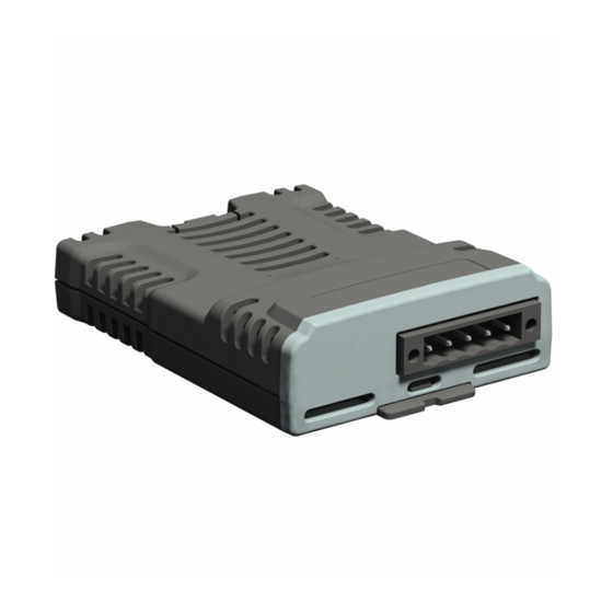
Option Module identification SI-DeviceNet can be identified by: 1. The label located on the top of the Option Module. 2. The color coding across the front of the SI-DeviceNet (dark grey). Figure 2-4 SI-DeviceNet labels SI-DeviceNet 1 Topside module label 2 Underside module label 2.5.1... -
Page 11: Mechanical Installation
Orientate the Option module above the drive as shown in (1). • Align and insert the Option module tab into the slot (2). Press down on the Option module until it clicks into place. SI-DeviceNet User Guide Issue Number: 2... -
Page 12: Electrical Installation
The external supply terminals provide power for the DeviceNet transceiver circuitry, but NOTE do NOT provide power to keep the SI-DeviceNet operating in the event of the mains pow- er supply loss to the drive. An external supply will keep the DeviceNet transceivers pow- ered up and the network load characteristics constant in the event of loss of power to the drive. -
Page 13: Si-Devicenet Connections
SI-DeviceNet connections To connect SI-DeviceNet to the DeviceNet network, make the connections as shown in the diagram below. The length of the "pigtail" shield connection must be kept as short as possible. Figure 4-2 SI-DeviceNet connections Cable SI-DeviceNet 2125576532 2 3 4 DeviceNet cable DeviceNet cable has 2 twisted pairs plus an overall shielding. -
Page 14: Devicenet Network Termination
SI-DeviceNet cable shield connections The SI-DeviceNet should be wired with the cable shields isolated from ground at each drive. The cable shields should be linked together at the point where they emerge from the cable, and formed into a short pigtail to be connected to pin 3 on the DeviceNet connector. -
Page 15: Devicenet Ground Point
The DeviceNet specification does not specify a minimum node to node distance, however, Control Techniques advises a minimum distance of 1 m between nodes to prevent excessive bend radii and to reduce network reflections. SI-DeviceNet User Guide Issue Number: 2... -
Page 16: Getting Started
Getting started This section is intended to provide a generic guide for setting up SI-DeviceNet and a master controller/PLC. Figure 5.1 Quick start chart SI-DeviceNet on page 17 is intended as the starting point for a new installation. The following pages detail the various methods available to configure SI-DeviceNet. -
Page 17: Quick Start Chart Si-Devicenet
Quick start chart SI-DeviceNet Start Set node address S.01.004 ) to a unique address (not 63) Set DeviceNet data rate S.01.005 Configure mappings S.02.001 S.02.028 and Pr S.03.001 S.03.028 Perform a drive save (Pr mm.000 = save parameters For drives on 24 V only use 1001... -
Page 18: Parameter Save And Restore
Module reset A reset of the SI-DeviceNet module can be performed by the methods detailed below. • Set Pr S.00.007 (or Pr MM.007) to On (1). This will only reset the module in slot S. - Page 19 Output processing S.01.025 0 to 65535 ms RO Num ND time Input consistency S.01.026 Disable (0) or Enable (1) Disable (0) RW enable Input consistency S.01.027 0 to 4.99.999 0.00.000 PT US trigger parameter SI-DeviceNet User Guide Issue Number: 2...
- Page 20 PT US Trap PM BL motor (10) FC DC Motor (2), WRI motor (6), SCI motor S.01.041 Motor 2 Type SCI motor (7), Sin PM BL motor (9), PT US Trap PM BL motor (10) SI-DeviceNet User Guide Issue Number: 2...
- Page 21 0 to 499999 RW Num S.02.026 Input mapping parameter 26 0 to 499999 RW Num S.02.027 Input mapping parameter 27 0 to 499999 RW Num S.02.028 Input mapping parameter 28 0 to 499999 RW Num SI-DeviceNet User Guide Issue Number: 2...
- Page 22 RW Num DE S.03.026 Output mapping parameter 26 0 to 499999 RW Num DE S.03.027 Output mapping parameter 27 0 to 499999 RW Num DE S.03.028 Output mapping parameter 28 0 to 499999 RW Num DE SI-DeviceNet User Guide Issue Number: 2...
- Page 23 Output Fault value 24 to 2 S.04.025 Output Fault value 25 to 2 S.04.026 Output Fault value 26 to 2 S.04.027 Output Fault value 27 to 2 S.04.028 Output Fault value 28 to 2 SI-DeviceNet User Guide Issue Number: 2...
- Page 24 Table 5.6 Menu 9 Resources Parameter Range( ) Default( ) Type S.09.030 PCB temperature -128 to 127 SI-DeviceNet User Guide Issue Number: 2...
-
Page 25: Parameters
The functionality and properties of the parameters are identical between the two menus. Module ID code Default S.00.001 Range 0 to 999 Access Pr S.00.001 displays the ID number for the Option Module. For SI-DeviceNet, this is 447. SI-DeviceNet firmware version Default S.00.002 Range 00.00.00.00 to 99.99.99.99 Access The firmware version of the Option module is in the format of ww.xx.yy.zz... - Page 26 SI-DeviceNet hardware version Default S.00.003 Range 00.00 to 99.99 Access The hardware version of the Option module is in the format of yy.zz Serial Number LS Default S.00.004 Range 0 to 99999999 Access Serial Number MS Default S.00.005 Range 0 to 99999999...
- Page 27 This sequence does NOT store the SI-DeviceNet configuration parameters in the drive NOTE or the SI-DeviceNet flash memory. This parameter will change back to Off immediately, and as such the change may not be visible on the display. Default DeviceNet Interface...
-
Page 28: Module Menu 1 - Devicenet Setup
This sequence does NOT store the SI-DeviceNet configuration parameters in the drive NOTE or the SI-DeviceNet flash memory. This parameter will change back to Off immediately, and as such the change may not be visible in the display. Default DeviceNet Interface... - Page 29 Pr S.01.005 will indicate the data rate that has been detected by the SI-DeviceNet. A value of -1 indicates that the SI-DeviceNet has not detected any activity on the DeviceNet network, and is waiting for the master controller to start communicating.
- Page 30 Access The network loss detection feature provides a method which ensures that communication with the master is still present. The SI-DeviceNet resets an internal timer when a valid message is received from the DeviceNet network, if a message is not received within the specified period, network loss is detected.
- Page 31 No Event (0) to Event4 (4) Access When a timeout occurs, the SI-DeviceNet module can trigger an event defined by Pr S.01.013 to a destination, such as an Option Module installed to a different slot on the drive, defined by Pr S.01.012.
- Page 32 32 (0) or 16 (1) bits Access By default, the SI-DeviceNet uses 32 bits for each data channel, even if the target parameter in the drive is a 16-bit parameter. This strategy (known as casting), ensures that the cyclic data transmitted over the DeviceNet network remains aligned with the memory locations in 32-bit PLC's.
- Page 33 Pr S.01.018 and S.01.019 control the input and output DeviceNet objects and also the number of polled words that are to be sent and received. Table 6.4 on page 34 shows the number of the polled words corresponding to Pr S.01.018 and Pr S.01.019. SI-DeviceNet User Guide Issue Number: 2...
- Page 34 Input assembly object Output assembly object Polled words (Pr S.01.018) (Pr S.01.019) There are several assembly objects that are covered in the DeviceNet specification that are available for use. See the DeviceNet objects chapter. SI-DeviceNet User Guide Issue Number: 2...
- Page 35 SI-DeviceNet input mapping status parameter (Pr S.01.022) and the SI-DeviceNet output mapping status parameter (Pr S.01.023). When a mapping error has been corrected, reset the SI-DeviceNet module by setting Pr S.01.002 or MM.007 to On (1).
- Page 36 The output processing time (Pr S.01.025) shows the time taken from the value being sent from the master to the value being successfully written to the drive in milliseconds. SI-DeviceNet User Guide Issue Number: 2...
- Page 37 If Input Consistency Action (Pr S.01.026) is set to On (1), the SI-DeviceNet module will check the value of the parameter specified by the Input Consistency Trigger Source Parameter (Pr S.01.027).
- Page 38 CAN frames will go off line. In this case, the SI-DeviceNet will trip the drive and it will not be possible to communicate with the drive via DeviceNet until the SI-DeviceNet has been reset.
- Page 39 When Pr S.01.034 is set to Disable (1), the BUS Off condition may still be entered, but the SI-DeviceNet does not trip the drive. Some external provision must be made to disable the drive when the process has reached a point at which it is safe to stop.
-
Page 40: Module Menu 2 - Input Mappings
0.00.000 Pr S.02.018 0.00.000 Pr S.02.019 0.00.000 Pr S.02.020 0.00.000 Pr S.02.021 0.00.000 Pr S.02.022 0.00.000 Pr S.02.023 0.00.000 Pr S.02.024 0.00.000 Pr S.02.025 0.00.000 Pr S.02.026 0.00.000 Pr S.02.027 0.00.000 Pr S.02.028 0.00.000 SI-DeviceNet User Guide Issue Number: 2... -
Page 41: Module Menu 3 - Output Mappings
0.00.000 Pr S.03.018 0.00.000 Pr S.03.019 0.00.000 Pr S.03.020 0.00.000 Pr S.03.021 0.00.000 Pr S.03.022 0.00.000 Pr S.03.023 0.00.000 Pr S.03.024 0.00.000 Pr S.03.025 0.00.000 Pr S.03.026 0.00.000 Pr S.03.027 0.00.000 Pr S.03.028 0.00.000 SI-DeviceNet User Guide Issue Number: 2... -
Page 42: Module Menu 4 - Fault Values
Pr S.04.012 Pr S.04.013 Pr S.04.014 Pr S.04.015 Pr S.04.016 Pr S.04.017 Pr S.04.018 Pr S.04.019 Pr S.04.020 Pr S.04.021 Pr S.04.022 Pr S.04.023 Pr S.04.024 Pr S.04.025 Pr S.04.026 Pr S.04.027 Pr S.04.028 SI-DeviceNet User Guide Issue Number: 2... - Page 43 Default S.09.030 Range -128 to 127°C Access PCB temperature 2 Default S.09.031 Range -128 to 127°C Access Parameters S.09.030 and S.09.031 display the current temperature of the 2 internal thermistors within the option module. SI-DeviceNet User Guide Issue Number: 2...
-
Page 44: Non Cyclic Data
“Explicit data” is the non cyclic data channel on DeviceNet that provides access to any parameter and DeviceNet object within SI-DeviceNet. As such, it is always enabled and active on SI-DeviceNet. Object access using explicit data is controlled entirely by the master controller program, and is not usually configured in any way when the DeviceNet network mapping is defined. -
Page 45: Control / Status Word
OK, drive at speed, etc. Control word The SI-DeviceNet control word consists of 16 control bits some of which are reserved. See Table 8.1 for the individual bit function descriptions. Table 8.1 Control word bit definitions... - Page 46 Once the watchdog is enabled it must be serviced at least once every second or an “Watchdog” trip will occur. The watchdog is disabled when a “Watchdog” trip occurs, and so it must be re-enabled when the trip is reset. Reserved SI-DeviceNet User Guide Issue Number: 2...
-
Page 47: Status Word
Status word The SI-DeviceNet status word consists of 16 control bits some of which are reserved. See the table below for the individual bit function descriptions. Reverse Reverse Brake Braking Current Supply Direction Direction Resistor IGBT Regenerating Limit Used Loss... - Page 48 DC bus voltage. This parameter can only become Pr 10.015 active if supply loss ride through or supply loss stop modes are selected. In regen mode, supply loss is the inverse of Pr 03.007. Reserved (Not Used) SI-DeviceNet User Guide Issue Number: 2...
-
Page 49: Eds Files
EDS Files What are EDS files? EDS (Electronic Data Sheets) files are text files that are used by SI-DeviceNet network configuration software tools. They contain information about the device, such as manufacturer, product type, product code, etc., and they also provide information on the default settings and functions supported by the device. -
Page 50: Advanced Features
1. Specify the input assembly object required in Pr S.01.018. 2. Specify the output assembly object required in Pr S.01.019. 3. Set Pr MM.007 to On to reset the SI-DeviceNet, and make the changes take effect. NOTE The parameter mapping of the pre-defined DeviceNet objects CANNOT be changed. - Page 51 The scanner must be configured for 6 Tx bytes (or 3 Tx words) if this output assembly object is selected. Table 10.5 Extended speed and torque control Data word Function Word 0 Extended control word (See below) Word 1 SpeedRef (See status word) Word 2 TorqueRef (See status word) SI-DeviceNet User Guide Issue Number: 2...
- Page 52 Basic status word (see below) Word 1 SpeedActual (see status word) The basic status word uses a full 16-bit word, with the bits having functions as shown below. DriveState RefFrom CtrlFrom Ready Running2 Running1 Warning Faulted Reference SI-DeviceNet User Guide Issue Number: 2...
- Page 53 SpeedActual (See status word) Word 2 TorqueActual (See status word) The extended status word uses a full 16-bit word, with the bits having functions as shown below. DriveState RefFrom CtrlFrom Ready Running2 Running1 Warning Faulted Reference SI-DeviceNet User Guide Issue Number: 2...
-
Page 54: Devicenet Objects
Attribute Access Returns the Vendor ID code, which is 0x101 (257) for Control Techniques. 11.1.2 DeviceType DeviceType Name: 0x01 Class Default 0x01 UINT Instance Data Type 0x02 Attribute Access Returns the Device Type code. SI-DeviceNet User Guide Issue Number: 2... - Page 55 Local Slot Pr 11.029 returns the major software revision number. Local Slot indicates the slot in which the SI-DeviceNet is installed: 0 = slot 1, 1 = slot 2, 2 = slot 3. Pr 11.084 returns the drive operating mode, e.g. open loop, closed loop, servo, etc.
- Page 56 0x06 Attribute Access Returns a serial number of the SI-DeviceNet. This value is entered during production, and cannot be edited. The serial number of the SI-DeviceNet can also be read from Pr MM.004 and Pr MM.005. 11.1.6 ProductName ProductName Name:...
-
Page 57: Si-Devicenet Object
The Data Rate is read from Pr S.01.007 at power up and reset. When this attribute is written to, the SI-DeviceNet will update the Data Rate in Pr S.01.007. The new value is not stored automatically, and the SI-DeviceNet is not reset. - Page 58 Table 11.5 Allocation byte Action Explicit Message Polled Strobed (Not supported) Reserved Change of State (Not supported) Cyclic (Not supported) Acknowledge Suppression Reserved SI-DeviceNet User Guide Issue Number: 2...
-
Page 59: Motor Data Object
2 is mapped to Pr 21.007. Pr 05.007 = RatedCurrent1 * 10 RatedCurrent1 = Pr 0.507 / 10 Pr 21.007 = RatedCurrent2 * 10 RatedCurrent2 = Pr 21.007 / 10 SI-DeviceNet User Guide Issue Number: 2... - Page 60 Data Type 0x0F Get/Set Attribute Access Specifies the base speed of the motor in rpm. Instance 1 is mapped directly to Pr 05.008 in the drive, and instance 2 is mapped directly to Pr 21.008. SI-DeviceNet User Guide Issue Number: 2...
- Page 61 11.3.6 Motor2Select Motor2Select Name: 0x28 Class Default 0x01 USINT Instance Data Type 0x64 Get/Set Attribute Access Selects between Motor Map 1 and Motor Map 2 in the drive. Pr 11.045 Pr 21.015 SI-DeviceNet User Guide Issue Number: 2...
-
Page 62: Control Supervisor
Set False terminal control Set True fieldbus control 11.4.4 State State Name: 0x29 Class Default 0x01 USINT Instance Data Type 0x05 Attribute Access This returns a code to indicate the current operating state of the drive. SI-DeviceNet User Guide Issue Number: 2... - Page 63 Get False (Pr 10.040 & 0x2002) != 0x2002 11.4.7 Faulted Faulted Name: 0x29 Class Default 0x01 USINT Instance Data Type 0x0A Attribute Access Indicates that the drive is tripped, i.e. not OK Pr 10.001 SI-DeviceNet User Guide Issue Number: 2...
- Page 64 0x2310 0x4300 0x5112 0x3130 11.4.10CtrlFromNet CtrlFromNet Name: 0x29 Class Default 0x01 USINT Instance Data Type 0x0F Attribute Access Indicates that the drive is operating under fieldbus control. Pr 06.042 bit 7 & Pr 06.043 SI-DeviceNet User Guide Issue Number: 2...
-
Page 65: Ac/Dc Drive Object
The reference can only be changed between local and remote when the drive is configured in speed control mode. If a change is requested when in torque mode then a ‘Device state conflict’ error code 10h will be returned. SI-DeviceNet User Guide Issue Number: 2... - Page 66 Pr 01.021 = (RPM * Pole Pairs) / 6 (Open Loop) RPM = (Pr 02.001 * 6) / Pole Pairs (Open Loop) Get/Set Pr 01.021 * 10 (Closed Loop, Servo) SI-DeviceNet User Guide Issue Number: 2...
- Page 67 11.5.8 RefFromNet RefFromNet Name: 0x2A Class Default 0x01 USINT Instance Data Type 0x0C Attribute Access Indicates the source of the speed reference. TRUE if Pr 01.049 = 3 and Pr 01.050 = 1 FALSE otherwise. SI-DeviceNet User Guide Issue Number: 2...
-
Page 68: Control Techniques Object
Slot 3 configuration. 18 (0x12) User application menu 1. 19 (0x13) User application menu 2 (not on M100-M400). 20 (0x14) User application menu 3 (not on M100-M400). 21 (0x15) Second motor map. Menu 0. SI-DeviceNet User Guide Issue Number: 2... -
Page 69: Diagnostics
12.1 Overview This section provides basic diagnostic information intended to resolve the most common problems encountered when setting up an SI-DeviceNet module on a DeviceNet network. A high percentage of problems reported are basic set-up problems which can usually be solved by reading the information in this chapter. - Page 70 Failed to write parameter during cyclic communication 12.1.3 DeviceNet error codes If the SI-DeviceNet module detects a DeviceNet error during operation, it will force a trip on the drive and provide a sub-trip string for a clearer definition of the trip. The table below shows all possible SI-DeviceNet error codes.
- Page 71 12.1.4 SI-DeviceNet network diagnostic The operating status of the SI-DeviceNet module can be viewed in the network diagnostic parameter (Pr S.01.006). All possible values of this parameter are described in Table 12.4. Table 12.4 SI-DeviceNet network operating status Value Text...
- Page 72 Reserved 12.1.6 Alarms If the SI-DeviceNet detects an alarm during operation, it will cause the drive to display the appropriate alarm on the drive keypad. If more than one alarm is present, it will be shown as “first-in-first-out” (FIFO) order.
-
Page 73: Glossary Of Terms
When a device sends or receives data the address is used to determine the source and the destination of the message. Alignment: By default SI-DeviceNet transmits values as 32 bits on the network. It is possible by using alignment to reduce the number of bits transmitted when sending 16- bit (or smaller) values on the network to 16-bit (32-bit values will still be transmitted as 32-bit values). - Page 74 Task ID: The code used to describe the purpose of a message using PPO 4 word non- cyclic communication. Termination: This is used at both ends of a network segment to prevent reflections and reduce noise. SI-DeviceNet User Guide Issue Number: 2...
- Page 75 Watchdog: A method used to determine if a communication system is ok/healthy. A typical watchdog scheme uses a handshaking system to check both the master and slave are participating in communications. Word: A collection of 16 binary digits. SI-DeviceNet User Guide Issue Number: 2...
- Page 76 Getting started ....................16 Glossary of terms ..................73 Hardware enable ..................45 Maximum network length ................15 Minimum node to node cable length ............15 Module menu 0 - Module Information ............25 Module menu 1 - DeviceNet Setup ............28 SI-DeviceNet User Guide Issue Number: 2...
- Page 77 Module menu 3 ...................41 Module menu 4 ...................42 Option Module identification ...............10 Parameters - adjusting .................6 Polled words ....................34 Quick start chart SI-DeviceNet ..............17 Regenerating ....................48 Running at or below minimum speed ............47 SI-DeviceNet cable shield connections ............14 SI-DeviceNet connections ................13 SI-DeviceNet network loss trip ..............50...
- Page 78 0478-0032-02...
Need help?
Do you have a question about the SI-DeviceNet and is the answer not in the manual?
Questions and answers