Table of Contents
Advertisement
Quick Links
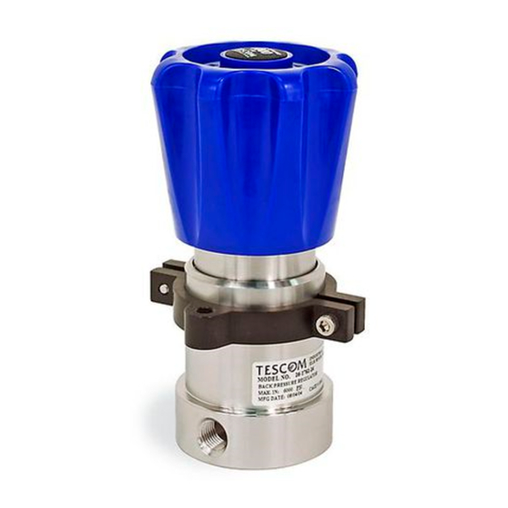
Safety, Installation, Operations & Service
TESCOM Product Manual
Do not attempt to select, install, use or
maintain this product until you have read
and fully understood this manual.
This manual is available in multiple languages online at www.tescom.com.
Operations & Service Manual
DOPMS2080X012
Rev. 06/15
Advertisement
Table of Contents


Need help?
Do you have a question about the TESCOM 04 Series and is the answer not in the manual?
Questions and answers