Emerson Sempell Series Operating Instructions Manual
Control device for safety valves
Hide thumbs
Also See for Sempell Series:
- Operating instructions manual (12 pages) ,
- Installation and maintenance instructions manual (10 pages) ,
- Installation and maintenance instructions (4 pages)
Table of Contents
Advertisement
Quick Links
Sempell SerieS STe 4 ConTrol DeviCe for SafeTy valveS
Operating instructiOns
Before installation these instructions must be fully read and understood
Series
STE 4 Control device for safety valves with
pneumatic actuator.
1 Danger anD Warning inDicationS
The construction of the Sempell safety
valves and control devices corresponds to
the standard technology and the valid safety
regulations.
nevertheless, improper use or improper
installation may cause risks for personnel
or can lead to restrictions in regard of the
operational safety. Therefore Sempell GmbH
recommends the operator of the valves to take
appropriate measures and make sure that
the present operating instruction is read and
understood by the assigned personnel.
please observe the following points besides
the notes given in the text
• Danger of burning when in contact with safety
valves and connecting pipes while operating
at increased temperature.
• Disassembly of the safety valve only in case
of pressureless system and after cooling
down. Wait for official permission. Disconnect
electrical supply.
• Protection against risks caused by
evaporation also in case of pressureless
system; for information please contact the
responsible safety inspector.
• After assembly check all sealing points in
regard of tightness.
• Carry ear protection during adjustment,
if necessary.
• Danger of burning by discharge of small
amounts of possibly hot medium in case
of safety valves with open spring bonnet
(type So..., vSe 1, vSr 1, vSe 8).
• Danger of injury while discharging in case of
open discharge line.
• Extreme vibrations (chatter) can lead to an
inadmissible increase of operating pressure
with possibly destruction of the safety valve
or to destruction of the balanced bellows with
unintentional escape of medium.
www.valves.emerson.com
exclusion of liability
Sempell GmbH cannot be held liable in case
of improper maintenance and adjustment of
a Sempell valve, use of inadmissible spare
parts or utilities and in case of temporary or
permanent connection of equipment with the
safety valve which is not approved by us.
Application limits
It is only allowed to use the safety valves and the
control device according to the details of this
operating instruction and/or according to the
parameters and application data agreed in the
delivery contract (see nameplate).
The application of the valve has to take place
adequate to the medium tolerances of the used
materials.
Warnings for the operating and maintenance
personnel
Before commissioning and maintenance works
familiarise yourself with the legal accident
prevention regulations, the local safety
instructions and this operating instruction and
observe them.
Use safety valve, control device and their
individual parts and accessories only for the
purpose intended by us.
Work on the electrical systems or equipment
must only be carried out by an electrician
or instructed personnel under control and
supervision of an electrician according to the
electrotechnical regulations.
© 2017 Emerson. All rights reserved.
Ma.330.02.0505.e
Vciom-02238-en 15/01
Advertisement
Table of Contents

Related Manuals for Emerson Sempell Series


Summary of Contents for Emerson Sempell Series
- Page 1 Sempell SerieS STe 4 ConTrol DeviCe for SafeTy valveS Operating instructiOns Before installation these instructions must be fully read and understood exclusion of liability Series STE 4 Control device for safety valves with Sempell GmbH cannot be held liable in case pneumatic actuator.
-
Page 2: Description Of Components
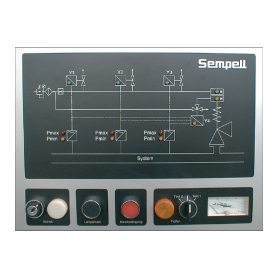
Sempell SerieS STe 4 ConTrol DeviCe for SafeTy valveS Operating instructiOns D3 a3 2 DeScription of componentS For the following sections the connection diagram section 9.2 is valid unless other provided. 2.1 Description of the function The type-tested control device STe 4 pilots... - Page 3 Sempell SerieS STe 4 ConTrol DeviCe for SafeTy valveS Operating instructiOns The electric switch unit includes the equipment for signal treatment and control. at the bottom side is the connection for the power supply. Protected by an inspection window, control lamps and manual switches for working and testing are on the front panel.
- Page 4 Sempell SerieS STe 4 ConTrol DeviCe for SafeTy valveS Operating instructiOns 3 technical Data Safety ValVe control Manufacturer Sempell GmbH name Control Device Series STe 4 Compressed-air supply Max. 8 bar, 12 bar as option operating pressure for the pneumatic actuator Max.
-
Page 5: Troubleshooting
Sempell SerieS STe 4 ConTrol DeviCe for SafeTy valveS Operating instructiOns 4.4 reseat pressure • The safety valve is opened and lifting air is applied: Increase pressure with the spindle pump connected at the test connection beyond the Electric switch unit: white control lamp “Operation”... - Page 6 Sempell SerieS STe 4 ConTrol DeviCe for SafeTy valveS Operating instructiOns Potentiometer Switch • Check of the control legs 1 to 3 • Set back to working conditions - Adjustment of the control air pressure to - Turn test switch into position “Operation”.
- Page 7 Sempell SerieS STe 4 ConTrol DeviCe for SafeTy valveS Operating instructiOns • Test course Solenoid valve y3 closes (nominal voltage at Y3). Load will be charged. Ampere meter into position “Operation”, Test switch in position “Operation”. • Adjustment of the working state - open the front door and the cover plate of the electric switch unit.
- Page 8 Sempell SerieS STe 4 ConTrol DeviCe for SafeTy valveS Operating instructiOns 4.7.5 Safety valve adjustment (system pressure) For the following tests only one observation is done at a random system pressure. in case of checking the spring setting of the...
- Page 9 Sempell SerieS STe 4 ConTrol DeviCe for SafeTy valveS Operating instructiOns The pneumatic actuator is temporarily switched 2. Check reliability of the main valve in off; the safety valve remains fully operational. connection with the control device. • In case of a cup spring safety valve 3.
-
Page 10: Preventive Maintenance
Sempell SerieS STe 4 ConTrol DeviCe for SafeTy valveS Operating instructiOns 6 preVentiVe maintenance 7 repair inStruction anD inStallation Observe safety instruction in section 1. Observe safety instruction in section 1. Before each operation ensure that Before each operation ensure that... - Page 11 Sempell SerieS STe 4 ConTrol DeviCe for SafeTy valveS Operating instructiOns 7.2 assembly in case of pressure sense lines coming from different systems (e.g. drum, superheater), take The delivery of the control device STe 4 takes place assembled on a frame tightened by eight...
-
Page 12: Installation
Sempell SerieS STe 4 ConTrol DeviCe for SafeTy valveS Operating instructiOns 7.4 compressed-air connection 7.6 Change of pressure switches D1, D2, D3 installation To install the pressure switch, observe the To connect the compressed-air supply the procedures control unit has a compressed-air connection assembly instruction of the producer of the tube fitting (product Parker) (see section 9.3). - Page 13 Sempell SerieS STe 4 ConTrol DeviCe for SafeTy valveS Operating instructiOns 7.7 Replacing (or cleaning) of the filter F 7.8 ordering of spare and reserve parts for spare parts storage or spare parts ordering During these works close the air supply of the control unit.
-
Page 14: Conformity Declaration
Sempell SerieS STe 4 ConTrol DeviCe for SafeTy valveS Operating instructiOns 8 Declaration to ec-DirectiVe For valves with CE-approval mark applies the following declaration: Declaration to ec-Directive: conformity Declaration According to Pressure Equipment Directive 97 / 23 / EG Manufacturer Sempell GmbH Werner von Siemens Straße... -
Page 15: Technical Documents
Sempell SerieS STe 4 ConTrol DeviCe for SafeTy valveS Operating instructiOns 9 technical DocumentS 9.1 Spare parts list Spare part liSt impulSe unit a161 part no. number of units name of part order no. / Dim. manufacturer material a1-a3 Shut-off valve Sempell Div. - Page 16 Sempell SerieS STe 4 ConTrol DeviCe for SafeTy valveS Operating instructiOns PNEUMATIC CONTROL UNIT A163 Design B2 Manual lifting IMPULSE UNIT A161 a = ..bar a = ..bar a = ..bar b = ..bar b = ..bar...
- Page 17 Sempell SerieS STe 4 ConTrol DeviCe for SafeTy valveS Operating instructiOns IMPULSE UNIT A161 Pressure A163 Travel air supply System pressure Pneumatic control unit A162 Power supply electrical switching unit A161 Pulse generating unit SySTeM CirCUiT DiaGraM Pneumatic control unit A163...
- Page 18 Sempell SerieS STe 4 ConTrol DeviCe for SafeTy valveS Operating instructiOns SySTeM CirCUiT DiaGraM Design with pressure regulator R2 for increased lifting air pressure noteS E1 - E3 Pressure sense line Pneumatic control unit A163 a1 - a3 Shut-off valve...
- Page 19 Sempell SerieS STe 4 ConTrol DeviCe for SafeTy valveS Operating instructiOns SYSTEM CIRCUIT DIAGRAM WITH TWO SAFETY VALVES lifting by manual operating (design B2) loading lifting Pressure superheater Pressure drum Sense line Safety valve drum Safety valve superheater Water lock...
- Page 20 Sempell SerieS STe 4 ConTrol DeviCe for SafeTy valveS Operating instructiOns 9.3 Installation instructions A-Lok tube fittings a-lok tube fittings are supplied completely assembled. General remarks 1. The end of the tube must be cut square; any burrs may be removed without causing undue chamfering of the tube end.
Need help?
Do you have a question about the Sempell Series and is the answer not in the manual?
Questions and answers