
Subscribe to Our Youtube Channel
Related Manuals for Emerson Shafer ECAT


Summary of Contents for Emerson Shafer ECAT
- Page 1 Installation, Operation and Maintenance Manual VA-DC-000-1952 Rev. 0 April 2021 Shafer ECAT Emission Controlled Actuator Technologies...
- Page 2 Notes Installation, Operation and Maintenance Manual April 2021 VA-DC-000-1952 Rev. 0 This page intentionally left blank...
-
Page 3: Table Of Contents
Installation, Operation and Maintenance Manual Table of Contents VA-DC-000-1952 Rev. 0 April 2021 Table of Contents Section 1: Introduction Scope ......................1 General Information ..................1 Safety Information ..................3 Abbreviation Definitions ................4 Section 2: Installation Preparation ....................5 Valve Preparation .................. -
Page 4: Section 1: Introduction
Overview The ECAT is a self-contained, quarter-turn, valve actuator that combines proven technologies from Emerson’s Valve Automation. The actuator has been designed for critical shutdown applications where reliability is crucial. The ECAT utilizes a hydraulic accumulator, pressurized with the pipeline gas, as a stored energy source in order to actuate the actuator / valve open or closed. - Page 5 Installation, Operation and Maintenance Manual Section 1: Introduction VA-DC-000-1952 Rev. 0 April 2021 1.2.6 Fluid Level in Reservoir The reservoir tank is provided with a stainless steel sight glass level viewer. 1.2.7 Functional Description The following is a functional description of the ECAT System for valve actuators and a brief explanation of the main components that make this ECAT system unique.
-
Page 6: Safety Information
Section 1: Introduction Installation, Operation and Maintenance Manual April 2021 VA-DC-000-1952 Rev. 0 Safety Information Safety notices in this manual detail precautions the user must take to reduce the risk of personal injury and damage to the equipment. The user must read these instructions in their entirety. Failure to observe these safety notices could result in serious bodily injury, damage to the equipment, void of the warranty. -
Page 7: Abbreviation Definitions
Installation, Operation and Maintenance Manual Section 1: Introduction VA-DC-000-1952 Rev. 0 April 2021 Abbreviation Definitions Abbreviations used in this manual and their definitions are listed in the table below: Table 1. Abbreviation Definitions Abbreviation Definition Installation Operation Manual Emergency Shutdown Fail-safe Double-Acting MAWP... -
Page 8: Section 2: Installation
2.1.1 Delayed Usage If for any reason the actuator is not to be installed immediately, Emerson Process Management recommends the following procedures. Failure to comply, with recommended procedures, could lead to actuator malfunction and possibly void the warranty. For storage procedures exceeding one year, consult Emerson Process Management for further recommendations. -
Page 9: Valve Preparation
Installation, Operation and Maintenance Manual Section 2: Installation VA-DC-000-1952 Rev. 0 April 2021 Valve Preparation 2.2.1 Remove Valve Gearing if equipped. 2.2.2 If valve is equipped with stops, remove valve stem extension housing. Examine the valve stops to ensure no foreign material is present that would restrict normal travel of the valve. Some valves are equipped with inspection ports in the valve housing for ease in examining the stops. -
Page 10: Lifting The Ecat System
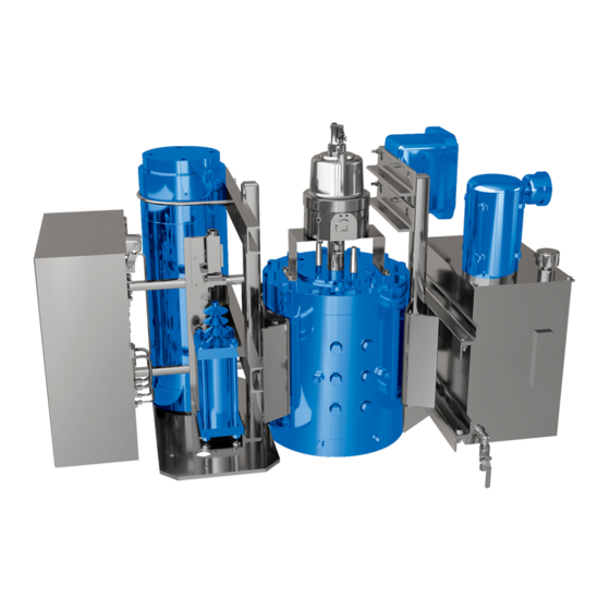
Section 2: Installation Installation, Operation and Maintenance Manual April 2021 VA-DC-000-1952 Rev. 0 Lifting the ECAT System NOTE: All ECAT Considerations When handling any ECAT actuator, be aware of tubing, accessories, handpump, accumulators, and control enclosures. Straps and chains can become entangled and cause damage to these components. NOTE: Do not use hydraulic tubing and electrical cable for lifting. - Page 11 Installation, Operation and Maintenance Manual Section 2: Installation VA-DC-000-1952 Rev. 0 April 2021 Figure 2 ECAT System Mounted on the Shafer Rotary Vane Actuator CAUTION Never lift the actuator with a valve attached. Always handle actuator / valve assemblies by attaching lifting equipment to the valve only.
-
Page 12: Installing The Ecat Actuator On The Valve
Section 2: Installation Installation, Operation and Maintenance Manual April 2021 VA-DC-000-1952 Rev. 0 Installing the ECAT Actuator on the Valve The actuator will be bolt-mounted directly to a bracket or adaptor that will be bolted securely to the mounting flange top works of the valve. 2.5.1 Check to see that the dimensions of the bracket or adaptor are suitable for use with the valve mounting flange and stem. -
Page 13: Hydraulic Fluid
Installation, Operation and Maintenance Manual Section 2: Installation VA-DC-000-1952 Rev. 0 April 2021 Hydraulic Fluid The ECAT actuators are shipped with the reservoir filled to operation level. Before commissioning and periodically afterwards, check to ensure the fluid level is correct. The reservoir is equipped with a sight gauge. - Page 14 Section 2: Installation Installation, Operation and Maintenance Manual April 2021 VA-DC-000-1952 Rev. 0 2.8.2 Pipeline Gas connections – Refer to schematic 11547-S Locate Upstream Isolation Valve (90) and Downstream Isolation Valve (91) (optional) for upstream and downstream pipeline gas connections, called out on the General Arrangement Drawing and Hydraulic Schematic (see Figure 3).
- Page 15 Installation, Operation and Maintenance Manual Section 2: Installation VA-DC-000-1952 Rev. 0 April 2021 Figure 3 PNEUMATIC MANIFOLD GAS PIPELINE 2.8.3 Pneumatic Fitting Leak Check With pipeline pressure applied to the pneumatic side of the ECAT circuit, check to ensure there are no leaks at the fittings.
-
Page 16: Section 3: Electrical Connections
Section 3: Electrical Connections Installation, Operation and Maintenance Manual April 2021 VA-DC-000-1952 Rev. 0 Section 3: Electrical Connections Main Electrical Connections Refer to the project specific wiring diagram for the electrical connections to the MCC. Sealing Cable / Conduit Entries Seal the cable and conduit entries in accordance with the National Electric Code or your country standard and applicable local codes. -
Page 17: Section 4: Set-Up / Start-Up Procedure
Installation, Operation and Maintenance Manual Section 4: Set-up / Start-up Procedure VA-DC-000-1952 Rev. 0 April 2021 Section 4: Set-up / Start-up Procedure In addition to this set-up / start-up procedure, the following documentation will be necessary to fulfill all set-up and start-up requirements. General Arrangement drawing Bill of Material Schematic drawing... -
Page 18: Initial Check Of The Unit
Section 4: Set-up / Start-up Procedure Installation, Operation and Maintenance Manual April 2021 VA-DC-000-1952 Rev. 0 Initial Check of the Unit 4.2.1 Check to ensure all hydraulic tube fittings are tight. Vibration during shipment may have loosened connections. 4.2.2 Visually inspect the unit to make sure tubing, hand valves, gauges and other equipment have not been damaged. - Page 19 Installation, Operation and Maintenance Manual Section 4: Set-up / Start-up Procedure VA-DC-000-1952 Rev. 0 April 2021 4.6.6 Verify all electrical connections are made per Section 3 of this procedure. Ensure the [Hand/Off/Auto] selector switch is set at Off. Turn main power on to the ECAT unit. The Power On light on the MCC should be illuminated.
-
Page 20: Final Start-Up Procedure
Section 4: Set-up / Start-up Procedure Installation, Operation and Maintenance Manual April 2021 VA-DC-000-1952 Rev. 0 Final Start-Up Procedure The system should already have the pipeline gas pressure applied to the pneumatic side of the system per Section 2.8. Verify the connections and pressure reading on Pneumatic Pressure Gauge (88). The header lines up to Power Oil Isolation Valve (73) should be filled and purged of all air per Section 4.6. -
Page 21: Section 5: Troubleshooting
Installation, Operation and Maintenance Manual Section 4: Set-up / Start-up Procedure VA-DC-000-1952 Rev. 0 April 2021 Section 5: Troubleshooting WARNING To prevent personal injury, all hydraulic pressure must be relieved from the accumulator before opening any tube lines or attempting replacement operations below. Of all the system components, the actuator itself is least likely to malfunction and require the most time and effort to service. -
Page 22: Section 6: Maintenance
Lubrication Requirements NOTE: Lubricant, other than listed below should not be used without prior written approval of Emerson Product Engineering. Hydraulic fluids, other than those listed below should not be used without prior written approval of Emerson Product Engineering. -
Page 23: Recommended Annual Inspection
• Check the breather on the hydraulic reservoir • Check the return filter, if included Qualified service personnel are available upon request. Please feel free to contact: EMERSON AUTOMATION SOLUTIONS ACTUATION TECHNOLOGIES Address: 2500 PARK AVENUE WEST ONTARIO, OH 44906... - Page 24 P. R. China Székesfehérvár 8000 T +86 22 8212 3300 Hungary The Emerson logo is a trademark and service mark of Emerson Electric Co. T +36 22 53 09 50 Shafer is a mark of one of the Emerson family of companies.
Need help?
Do you have a question about the Shafer ECAT and is the answer not in the manual?
Questions and answers