Emerson Site Supervisor User Manual
Hide thumbs
Also See for Site Supervisor:
- Quick setup manual (10 pages) ,
- Quick setup manual (9 pages)
Table of Contents
Advertisement
Quick Links
Advertisement
Table of Contents

Related Manuals for Emerson Site Supervisor


Summary of Contents for Emerson Site Supervisor
- Page 1 Site Supervisor Controller User Guide 2.0 026-1800 Rev 3 02-AUG-2016...
- Page 3 CE COMPLIANCE NOTICE Class A Product Information for Site Supervisor controllers: The Emerson Retail Solutions Site Supervisor controllers are Class A products. In a domestic environment this product may cause radio interference in which case the user may be required to take adequate measures.
- Page 4 ULE211299 ELECTROSTATIC DISCHARGE CAUTION This integrated circuit can be damaged by ESD. Failure to observe proper handling and installation procedures can cause damage. ESD damage can range from subtle performance degradation to complete device failure. Precision integrated circuits may be more susceptible to damage because very small parametric changes may cause the device to not meet its published specifications.
-
Page 5: Table Of Contents
2.2.10 8DO Digital Output Board ..........................2-8 2.2.11 XM Series of Case Controllers......................... 2-9 2.2.11.1 XM670 ................................... 2-9 2.2.11.2 XM679 ................................... 2-9 2.2.11.3 XM678 ................................... 2-9 2.2.12 Site Supervisor Display..........................2-10 Site Supervisor Controller User Guide 2.0 Table of Contents • i... - Page 6 3 WIRING EXAMPLES............................... 3-1 4 SITE SUPERVISOR DISPLAY ..........................4-1 4.1 T ............................. 4-2 ECHNICAL PECIFICATIONS 4.2 M ................................. 4-2 OUNTING 4.2.1 Panel Mount Dimensions ........................... 4-2 4.2.2 Wall Mount Dimensions ............................. 4-3 4.3 E ............................4-4 LECTRICAL ONNECTIONS 4.3.1 Panel Mount Version............................4-4 4.3.2 Wall Mount Version ............................
- Page 7 5.9.3.2 Average Rate of Consumption Output........................5-20 5.9.3.3 Demand Alarm............................... 5-20 5.9.3.4 Time In Shed Output.............................. 5-20 5.9.4 Application Specific Logs..........................5-20 5.9.5 Units of Measurement ............................5-20 5.10 O I/O ............................... 5-20 OARD Site Supervisor Controller User Guide 2.0 Table of Contents • iii...
- Page 8 5.9.1 Licensing ................................5-20 5.9.2 Adding and Deleting Onboard I/O Application ....................5-20 5.9.3 Status and Detail Screen ..........................5-21 5.9.4 Alarming................................5-22 5.10 XR75CX 5.6................................5-22 5.11 XR35CX 5.6 2.6............................5-23 5.11.1 Overview................................. 5-23 5.11.2 Command-Alarm Matrix ..........................5-24 5.12 XC645CX 2.5................................
- Page 9 6.2.1.1 User View Details ..............................6-2 6.3 B ........................6-3 ASIC CREEN ARTS AND LEMENTS 6.4 L ..............................6-3 ANGUAGE ETTINGS 6.5 L ............................6-3 OCATING PPLICATIONS 6.6 U ............................6-4 SING THE Site Supervisor Controller User Guide 2.0 Table of Contents • v...
- Page 10 6.7 I ..................6-5 CONS OR UTTONS PPEARING ON THE CREEN 7 ALARM CONFIGURATION ........................... 7-1 7.1 A ............................7-2 LARM ONFIGURATION 7.2 A ........................7-2 LARM OMMUNICATIONS ETTING 7.3 A ..........................7-3 LARM OG AND ISTORY 7.4 T ........................7-4 EMPERATURE IFFERENTIAL LARMS...
-
Page 11: Hardware Overview
This system provides HVAC control, Refrigeration System Monitoring and Control, as Housing Dimensions well as Lighting Control. In addition, the Site Supervisor can monitor and report energy consumption and take and Mounting action to reduce the energy demand during peak periods. -
Page 12: Wiring Diagrams
Wiring Diagrams Figure 1-2 - Site Supervisor 2.0 Wiring Diagram • Site Supervisor Controller User Guide 2.0 026-1800 Rev 3 02-AUG-2016... - Page 13 Figure 1-3 - Site Supervisor 2.0 Detail • Wiring Diagrams Hardware Overview...
-
Page 14: Device Wiring
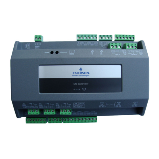
See Section 3, Wiring Examples for typical power and COM wiring. Site Supervisor Power, Serial, and IO Positions Figure 1-4 - Site Supervisor Power, Serial, and IO Positions 1.5.1 Termination Jumpers Depending on the orientation of the board, the termination jumpers are set in the down position (always toward the board - ON) for termination and up (always away from the board - OFF) for no termination. -
Page 15: Removing The Sd Card
Solid red Loading OS/Application Flashing red - 1 Hz Running - Normal Status Solid green Failure to load Flashing red - 2 Hz Table 1-2 - LED States and Definitions • Site Supervisor Power, Serial, and IO Positions Hardware Overview... -
Page 16: Wiring Terminal Detail
Wiring Terminal Detail Figure 1-7 - Site Supervisor Wiring Terminal Detail Digital Inputs • Can read pulses up to 10Hz Relay Outputs Figure 1-8 - Digital Inputs • Can read both dry and wet (24VAC) contact Figure 1-9 closures - Relay Outputs •... -
Page 17: Analog Inputs
Figure 1-10 - Analog Inputs • Supports 0-10VDC, 0-1 DC, 0-5VDC, 2-20mA, 4-20mA, Emerson NTC temperature and dry contact digital input. • Supports engineering units for temperature, pressure, humidity, light level and generic percentage. • When wiring transducers or amplifiers (for example, outdoor light level) the odd numbered terminal is the + or sig- nal and the even numbered terminal is the –... -
Page 18: Serial Connections
Site Supervisor 2.0 is equipped with four (4) RS485 serial Com ports and one (1) Can Bus port. • Com ports 1-4 support MODBUS and Emerson (CPC) IO Net. (Com Port 4 = Site Supervisor display only) • Com ports 1-4 support 9600, 19200, 38400, 57600, and 115200 baud connection speeds. (Com Port 4 = Site Super- visor display only) •... -
Page 19: Rs485 I/O Network Boards And Peripherals
Peripherals I/O board. 2.2.1.1 MultiFlex 16 Input Board Site Supervisor has up to two RS485 network ports, each of which may be configured as an I/O network or MODBUS port. The I/O Network Most of the general purpose input and output... -
Page 20: Multiflex Combination Input/Output Boards
The MultiFlex combination I/O boards consist of up to 16 combination digital/analog inputs, and a combination of relay outputs, digital outputs, and analog outputs. Figure 2-3 - Non-RoHS MultiFlex Combination Input/Output Board (Top View) • Site Supervisor Controller User Guide 026-1800 Rev 3 02-AUG-2016... -
Page 21: Multiflex Rtu Support
168DO relay outputs, 4 digital out- You can create an instance of RTU application even if puts the RTU board is not connected to the Site Supervisor 810-3072 MultiFlex 16 analog/digital inputs, 16 controller, however the board status is displayed “Offline”. -
Page 22: Zone Management
When an RTU application is associated with a zone, The Site Supervisor downloads all setpoints and some inputs of RTU application should use the output configuration parameters you changed from UI values from zone. -
Page 23: Creating An Instance Of Rcb Application
You can create an instance of RCB application even if 2.2.3.6 Alarming the RCB board is not connected to the Site Supervisor controller, however the board status is displayed “Offline”. Alarms generated from RCB board will be received If the RCB board is connected to Site Supervisor... -
Page 24: Multiflex Rtu
RS485 I/O NETWORK 10 HAND-HELD TERMI- algorithms. It may operate in stand-alone mode, or it may NAL JACK interface with an Site Supervisor or BCU to control the RCB INPUTS 1-8 RELAY OUTPUT store environment in zones and pass along logging and CONNECTORS alarm information. -
Page 25: Hand-Held Terminal (P/N 814-3110)
The 8RO (P/N 810-3005) board is a general-purpose several of Retail Solutions' existing and legacy products. board used to connect an Site Supervisor to any of eight The HHT can be used on any Retail Solutions product standard control relay outputs, but is now obsolete and has with an RJ-11 connector. -
Page 26: 4Ao Analog Output Board
1 and 2. The 4-20mA outputs provide a variable maintained by a simple contact closure sequence are current for applications that are either externally powered effectively operated by the Site Supervisor. or that require power from the 4AO board. The 8RO board is easily installed and operated within the Retail Solutions Network environment because of its straightforward design. -
Page 27: Xm Series Of Case Controllers
2.2.11 XM Series of Case about the device. Controllers The XM series is a set of digital case controllers for low to medium units. The XM series control refrigeration solenoids and defrost (electric or hot gas), evaporator fans, lights and have an auxiliary output. 2.2.11.1 XM670 Figure 2-14 - XM679 2.2.11.3 XM678... -
Page 28: Site Supervisor Display
Figure 2-16 - Site Supervisor Display The Site Supervisor display (P/Ns 818-9022 and 818- 9023) is a remote UI for the Site Supervisor that connects to the controller using RS485 network to Serial Port D. The Site Supervisor display shows a simplified UI that... - Page 29 Wiring Examples Figure 3-1 - Site Supervisor and MultiFlex Wiring • Wiring Examples...
- Page 30 Figure 3-2 - Site Supervisor and XR35CX 120V Wiring • Site Supervisor Controller User Guide 026-1800 Rev 3 02-AUG-2016...
- Page 31 Figure 3-3 - Site Supervisor and XR35CX 230V Wiring • Wiring Examples...
- Page 32 Figure 3-4 - Site Supervisor and XR75CX and IPX Wiring • Site Supervisor Controller User Guide 026-1800 Rev 3 02-AUG-2016...
- Page 33 Figure 3-5 - Site Supervisor and XR75CX Wiring • Wiring Examples...
- Page 34 Figure 3-6 - Site Supervisor and XM670 Wiring • Site Supervisor Controller User Guide 026-1800 Rev 3 02-AUG-2016...
- Page 35 Figure 3-7 - Site Supervisor and XM678 Wiring • Wiring Examples...
- Page 36 Figure 3-8 - Site Supervisor and XM679 Wiring • Site Supervisor Controller User Guide 026-1800 Rev 3 02-AUG-2016...
- Page 37 Figure 3-9 - Site Supervisor and XEV22 Wiring • Wiring Examples...
- Page 38 Figure 3-10 - Site Supervisor and XEV30 Wiring • Site Supervisor Controller User Guide 026-1800 Rev 3 02-AUG-2016 3-10...
- Page 39 Figure 3-11 - Site Supervisor and XEV32 Wiring • Wiring Examples...
- Page 40 Figure 3-12 - Site Supervisor and Energy Meter Wiring • Site Supervisor Controller User Guide 026-1800 Rev 3 02-AUG-2016 3-12...
- Page 41 Figure 3-13 - Site Supervisor and Thermostat Wiring • Wiring Examples...
- Page 42 Figure 3-14 - Site Supervisor and the Display • Site Supervisor Controller User Guide 026-1800 Rev 3 02-AUG-2016 3-14...
- Page 43 Figure 3-14 - Site Supervisor and iPro-S Wiring • Wiring Examples...
- Page 44 Figure 3-15 - Site Supervisor and iPro-G Wiring • Site Supervisor Controller User Guide 026-1800 Rev 3 02-AUG-2016 3-16...
-
Page 45: Site Supervisor Display
- Site Supervisor Display The Site Supervisor display (P/Ns 818-9022 and 818- 9023) is a remote UI for the Site Supervisor that connects to the controller using RS485 network to Serial Port D, and shows a simplified UI that allows users to perform... -
Page 46: Technical Specifications
RH Sensor: 20 to 85% 32.18°F (0.1°C) NTC Resolution ±3% (20 to 80%) Accuracy Humidity ±5% (elsewhere) Sensor -4 to 140°F Operating Tempera- (-20 to 60°C) ture Table 4-1 - Site Supervisor Specifications • Site Supervisor Controller User Guide 2.0 026-1800 Rev 3 02-AUG-2016... -
Page 47: Wall Mount Dimensions
4.2.2 Wall Mount Dimensions Figure 4-3 - Dimensions for Wall Mounting - Sizes in mm • Mounting Site Supervisor Display... -
Page 48: Electrical Connections
The Site Supervisor display connects to the Site Supervisor via the RS485 Network using Belden #8761 cable or equivalent. Connect to the Site Supervisor using only Com 4. This is a dedicated Com port for the Site Supervisor display and therefore does not require software setup. -
Page 49: Wall Mount Version
Press OK on the Site Supervisor display. The display will turn itself off momentarily and show a blank screen. Two separate audible tones will sound followed immediately by a third longer tone to indicate the firmware has been successfully updated. -
Page 50: Dip Switch Configuration
BACK button. Figure 4-7 - Keypad - Back, Delete, and SUBMIT Once the Site Supervisor display has been powered up, the first screen that appears is the Emerson launch screen below (Figure 4-8). It will appear for five seconds:... - Page 51 - Choose Desired Category New Units) Once logged in, depending on user permissions, select The Site Supervisor may be configured to communi- the desired category. cate across an Ethernet computer network using TCP/IP protocol. To enable Ethernet communication, you will...
- Page 52 HVAC Control Example Scheduling System Configuration Table 4-2 - Site Supervisor Display Icons and Definitions Lighting Control Example Figure 4-16 - HVAC Applications and Status Information Touch the HVAC icon to view, edit, or override HVAC information.
- Page 53 Energy Control Examples Figure 4-20 - Select The Desired Application Schedule Touch the Lighting, HVAC, Energy, or Other icons to access those applications and see Scheduling options. Figure 4-23 - Energy Applications Display • Site Supervisor Display Screens Site Supervisor Display...
- Page 54 To access IP Address information, select IP In this example, Emrs T-Stat_004 has been selected. ADDRESS in System Settings: Alarm information for that application displays: Figure 4-26 - Alarm Display Information (T-Stat) • Site Supervisor Controller User Guide 2.0 026-1800 Rev 3 02-AUG-2016 4-10...
- Page 55 - Date, Time, and Zip Code Information For Emerson contact information, touch CONTACT Figure 4-33 - Auto Log Out Screen EMERSON in System Settings and the contact screen dis- plays: Figure 4-31 - Emerson Contact Information To access Site Supervisor information, touch PROD- UCT INFO in System Settings: •...
-
Page 56: Software Overview
For example, if the application says that 60% of the total compressor rack’s power should be active, and the rack has compressors totaling 50 HP, then Site Supervisor Suction Groups will try to switch on compressors totaling 30 HP. -
Page 57: Learning Mode
The default setting, “Moderate Control,” seeks to bal- ance good suction pressure control with efficient cycling. • Site Supervisor Controller User Guide 2.0 026-1800 Rev 3 02-AUG-2016... -
Page 58: Analog Sensor Control
LIQUID RECEIVER CIRCUIT Wiring CASE TEMP Input Sensor Type (FOR FLOATING) Instructions Suction 100 lb. Eclipse (see Table 9-1 on LIQUID LINE Pressure transducer page 9-3) SOLENOID Discharge 500 lb. Eclipse (see Table 9-1 on Pressure transducer page 9-3) DISCHARGE SUCTION PRESSURE 200 lb. -
Page 59: Control Alarming
DEMAND SHED except the primary demand shed has priority if they are both ON. The Stpt Bump Rst Int indicates the amount of time over which the setpoint is • Site Supervisor Controller User Guide 2.0 026-1800 Rev 3 02-AUG-2016... -
Page 60: Alarm Output When On/Off Parameters
5.2.3 Alarm Output When On/Off • AND - logical AND of inputs Parameters • OR - logical OR of inputs • XOR - logical XOR of inputs Alarm When On redefines the definition of “active” as it refers to the state of the Alarm output. When the Sensor •... -
Page 61: Command Alarming
Choose Logic, Sched, Llev, or Solar. • Logic 1 - Chooses the method of combining Input Source 1 with Input Source 2 (AND or OR). If you • Site Supervisor Controller User Guide 2.0 026-1800 Rev 3 02-AUG-2016... -
Page 62: Light Level Sensor Verification
5.4.5 Light Proofing are only using one Input Source for this equation, leave the Logic 1 field blank. Light output proofing is supported by the application. • Input 2 - Choose the type of input value that is used The following parameters are provided by the as the second value in the logical equation. -
Page 63: Dimming Control (Analog Output)
Global Data’s LIGHT LEVEL The maximum % output corresponds to a minimum Light OUT output. If there is no Site Supervisor Level input. Anything below the minimum Light Level controller on the network with a Light Level sensor input results in the maximum % output. -
Page 64: External Schedule
Global Data time to wait before alarming if the above conditions are not satisfied. The Global Data application is the central location for • Llev Pr Delay - Light level proofing alarm delay. commonly used data values and limited data calculations The Light Level Proof Delay is the amount of time such as degree days and seasonal determination. -
Page 65: Hvac Control
The AHU determines which sensor should be used to provide overall control to the space being conditioned, for • WINTER HEAT OCC - This field is the setpoint example, the control temperature. The control temperature • 5-10 Site Supervisor Controller User Guide 2.0 026-1800 Rev 3 02-AUG-2016... -
Page 66: Heating And Cooling Control
can be a single space temperature, a combination of two to the Cool Stage Delay. If the temperature is still space temperatures, or the return air temperature. above the cool setpoint (plus one-half the deadband) it activates the next stage of cooling. The Controlled By parameter specifies which sensor Similarly, after a cool stage is deactivated, the AHU is used as the control temperature. -
Page 67: Fan Mode
(depending on the climate), the economization is disabled. Failures that can lock out amount of enthalpy in the air is acceptable and no economization are: • 5-12 Site Supervisor Controller User Guide 2.0 026-1800 Rev 3 02-AUG-2016... -
Page 68: Determine The Analog Damper Position
• Fan Proof Fail - When fan proof failure is stage (HEAT STAGE 1). If a second stage of heat is detected, heating and cooling loads are shut down required, two heat stages should be defined. Likewise, for until the proof failure goes away or the fan proof cooling, if one heat pump stage and one standard cooling alarm is reset or cleared. -
Page 69: Time Schedule Application
Master Schedule, in which positive time represents how much time after and negative time represents how much time ahead of what is • 5-14 Site Supervisor Controller User Guide 2.0 026-1800 Rev 3 02-AUG-2016... -
Page 70: Output Calculation
control directly and in these cases the user is able to enable Time to 23:59. demand shedding of the output. If the Demand Control NOTE: The Start Time is not the time you wish Input indicates shed and if the schedule output is On, it is for the maintenance override to make a state turned Off. -
Page 71: Control Override
Master's special event. value specified in the Emergency Out field. BYPASS - When the Bypass to ON input is ON, the schedule ignores its own scheduled events • 5-16 Site Supervisor Controller User Guide 2.0 026-1800 Rev 3 02-AUG-2016... -
Page 72: Control Alarming
and bypasses the schedule output ON. When the varying sampling frequency of the input signal to Bypass to OFF input is ON, the schedule ignores produce an energy calculation. its own scheduled events and bypasses the • Digital Energy Pulse Input (Digital KWh pulse schedule output OFF. -
Page 73: Shed Outputs
• After a load is restored, the staging interval timer is • 5-18 Site Supervisor Controller User Guide 2.0 026-1800 Rev 3 02-AUG-2016... -
Page 74: Performance Requirements
5.8.6 Performance Requirements 5.9.1.2 Analog Input When an analog usage rate signal input is selected, the KWH Pulse Input application calculates energy consumption on a weekly, When configured for KWH pulse input, the daily, and monthly basis by integrating the instantaneous Demand Control application must detect 100% of power samples (approximation by finite steps). -
Page 75: Fixed Period Totalizers
5.9.3.3 Demand Alarm The Site Supervisor has the onboard inputs and outputs The application provides an application alarm to signal which are initially supported by the controller. a high demand. The demand alarm limit and alarm delay will be configurable. -
Page 76: Status And Detail Screen
Description Size Limits Conf Probe 1 4 bit ntc(0) - Ptc(1) - 2/20mA(2) - 4/20mA(3) - 0/10V(4) - 0/1V(5) - 0/5V(6) - DIG(7)-e_ntc(8) Conf Probe 2 4 bit ntc(0) - Ptc(1) - 2/20mA(2) - 4/20mA(3) - 0/10V(4) - 0/1V(5) - 0/5V(6) - DIG(7)-e_ntc(8) Conf Probe 3 4 bit ntc(0) - Ptc(1) - 2/20mA(2) - 4/20mA(3) - 0/10V(4) - 0/1V(5) - 0/5V(6) - DIG(7)-e_ntc(8) -
Page 77: Alarming
The fourth probe is used to control the condenser temperature (for condenser alarm management) or to display a temperature value. Set the PbC parameter to CtC to support standard Emerson Retail Solutions temperature sensors (factory default). The controller is fully configurable through special parameters that can be easily programmed through the keyboard. -
Page 78: Xr35Cx 5.6 And 2.6
Close or Edit these controls. XR35CX and alarming. The XR35CX is networked with the Site Supervisor to share sensor data with a Case The system will display the new application(s) on Circuit application that controls the case refrigeration. It the Site Summary screen. -
Page 79: Command-Alarm Matrix
The front panel is locked and cannot be used. Keyboard UNLOCKThe front panel is unlocked and can be used. Alarms Muting Silences the alarm output. Table 5-5 - Diagnostic Alarms • 5-24 Site Supervisor Controller User Guide 2.0 026-1800 Rev 3 02-AUG-2016... - Page 80 The following is an example of the application status screen in UltraSite. This property can be added to the Site Supervisor’s general property. Input Value: Units: Status: Output Property: Value: Units: Status: Property: CONTROL TEMP NONE DEFR TERM TEMP NONE MIXED TEMP NONE ACTIVE SETPT...
-
Page 81: Xc645Cx 2.5
Table 5-7 - XC645CX 2.5 Application Advisories the application by setting the Edit Mode to ON on the screen drop-down arrow on the upper right of the screen. • 5-26 Site Supervisor Controller User Guide 2.0 026-1800 Rev 3 02-AUG-2016... -
Page 82: Command-Alarm Matrix
LOAD 6 ALARM Load 6 Alarm LP SWITCH ALARM Low Press. LP Switch HP SWITCH ALARM High Press. HP Switch ELECTRONIC LP Electronic low press DGS DLT ALARM Digital Scroll High Discharge Line temp Table 5-7 - XC645CX 2.5 Application Advisories 5.12.2 Command-Alarm Matrix Command Description/Alarm Text... - Page 83 DIGITAL % MOD NONE SUCTION AVERAGE NONE ERROR SUCT NOTACT ERROR DISCH NOTACT CFG ERROR AL NOTACT EEPROM FAIL AL NOTACT Table 5-9 - XC645 Status Screen Properties • 5-28 Site Supervisor Controller User Guide 2.0 026-1800 Rev 3 02-AUG-2016...
-
Page 84: Xr75Cx Case Display
Site Supervisor will provide an interface to the XR75CX CD and alarming. The XR75CX CD can be networked with Site Supervisor to share sensor data with a Standard Circuit application that controls the case refrigeration, and it has four on-board relays that can be used as satellite outputs by the other Site Supervisor applications. -
Page 85: Inputs
Supervisor is interrupted, the case display will go into Standalone (failsafe) mode. The value of Realy1FailSafe could be tested by the value of the corresponding relay in Standalone mode. • 5-30 Site Supervisor Controller User Guide 2.0 026-1800 Rev 3 02-AUG-2016... -
Page 86: Xr75Cx 2.6
5.14 XR75CX 2.6 the application by setting the Edit Mode to “ON” on the screen drop-down arrow on the upper right of the screen. Model XR75CX 2.6 (32 mm x 74 mm) is a micropro- cessor based controller, suitable for applications on medium or low temperature ventilated refrigeration units. -
Page 87: Command
The front panel is locked cannot be used. changed on the device using dip switches. Keyboard UN-LOCK The front panel is unlocked and can be • The Site Supervisor will just provide an interface to used. the devices. The White Rodgers Thermostat Alarms Muting Silences the alarm output. -
Page 88: Energy Meter
Alarm Select the Control or Application Type - type, priority, and the message for each alarm are user- Emerson Energy Meter 0.2, enter the Quantity, configurable. Control Name and Serial Type. Note that Serial Equations used to calculate output values and time Type information can be entered later. -
Page 89: Rlds (Refrigerant Leak Detector System)
The MRLDS communicates with the Site Supervisor with other applications and devices and copy built-in or analog input via MODBUS. Site Supervisor provides an properties of an instance of an HVAC Zone. interface while the MRLDS provides the leak monitoring 5.22.1 How It Works... -
Page 90: Compatible Applications To Be Connected To Hvac Zones
When a rooftop unit or AHU is associated with an is responsible for controlling the setpoint using its own HVAC Zone, the Site Supervisor automatically makes a temperature input. series of I/O connections between the HVAC Zone The HVAC Zone application pass along eight different application and the individual MultiFlex RTU or AHU setpoints, which are shown in Table 5-14. -
Page 91: The Effect Of Enabling Economization
Zone application’s HVAC Zone Humidity input to the output of the combiner. Both MultiFlex RTU and AHU applications support the use of both two-position (digital) and variable-position (analog) economizers. Digital economizers, when enabled, • 5-36 Site Supervisor Controller User Guide 2.0 026-1800 Rev 3 02-AUG-2016... -
Page 92: Enabling Dehumidification Effect
5.22.10 Enabling Dehumidification “coast” down to the unoccupied setpoint. Effect When an HVAC Zone application determines that dehumidification is needed, it sends an ON signal to all its associated controllers, signaling them to begin dehumidification. It is up to the individual MultiFlex RTU, RCB, or AHU to perform the dehumidification. -
Page 93: Ahu
A common application for this is in the HVAC control where a single heating control value comes from the average number of temperature sensors throughout the building. • 5-38 Site Supervisor Controller User Guide 2.0 026-1800 Rev 3 02-AUG-2016... -
Page 94: Anti-Sweat Control
5.25 Anti-Sweat Control Two different types of Multiple Input cells may be used if the inputs to be combined are analog or digital sources. A case controller manages its anti-sweat heaters by Inputs: monitoring the dewpoint in and around the case area. The In addition to the 16 analog inputs, combined Analog dewpoint input value is compared to the anti-sweat appli- Input 1 to 16, these inputs is combined based upon the... -
Page 95: Standard Circuits
CCB case controller. These cases must use CCBs for case control rely on Case Circuit Control appli- Case Circuit Control applications. cations in the Site Supervisor to provide them the neces- sary setpoints, defrost scheduling, and other control The Standard Circuits application provides supervisory parameters. -
Page 96: Case Circuit Control Software Overview
5.27.2 Case Circuit Control vary the aperture rates of both valves between 0% and 100% as required by their temperature control algorithms Software Overview (see Section 5.27.3, below). There are six different versions of case control soft- Pulse Valves ware in the Retail Solutions case control family: A pulse valve is a device capable of being in only two •... -
Page 97: Refrigeration Control
When the Recovery Mode ends, scheduled by the Site Supervisor. the superheat will be relatively close to the setpoint; at this • 5-42 Site Supervisor Controller User Guide 2.0 026-1800 Rev 3 02-AUG-2016... -
Page 98: Defrost States
5.27.4.1 Defrost States defined Pump Down and Run-Off times will be observed as normal. The defrost cycle for a Case Circuit application con- Electric Defrost sists of three steps. Of these three, steps #1 and #3 apply only to cases with heated defrosts: Electric defrost uses electric heaters to defrost the evaporator coil. -
Page 99: Emergency Defrost
CCB demand defrost is cur- Summaries and Floor Plans> Site Summaries> rently not supported in Site Supervisor. Demand sensors, if Other, click the screen drop-down arrow on the present on the circuit, will be ignored. -
Page 100: Temperature Differential (Td) Strategy
Setpoint greater than the Fan On Delay Time setpoint (or will turn on immediately if the last change was more than the Fan If the Drop Leg temperature drops below the mini- On Delay). Additional fans will be staged on at Fan On mum drop leg temperature setpoint (Drop Leg Min) a Delay intervals while an increase in capacity is called for. -
Page 101: Inputs
For TD Delay, if the TD alarming feature is used, enter the amount of time the TD must be higher than the setpoint before an alarm will be generated (HHH:MM) • 5-46 Site Supervisor Controller User Guide 2.0 026-1800 Rev 3 02-AUG-2016... -
Page 102: Loop/Sequence Control
XM Circuit Control application in The PID Control algorithm is similar to the PID algorithm the Site Supervisor to provide them the necessary set- used by Pressure Control, except the Loop Sequence points, defrost scheduling, and other control parameters. -
Page 103: Synchronized Parameters
Suction groups is performed from within the Enhanced 5.31.3.4 Defrost Scheduling Suction group setup. When editing the Suction Group The XM Circuit application provides defrost schedul- parameter in the XM Circuit application, only Standard • 5-48 Site Supervisor Controller User Guide 2.0 026-1800 Rev 3 02-AUG-2016... -
Page 104: Case States
ing to the associated XM case controllers. STA and CASE DEFR STA. Based on the value of these two input properties, one of the three case states listed in Defrost Start Mode Table 5-17 is selected and written to the corresponding Defrosts may be initiated with one of the following CASE STATE OU output property. -
Page 105: Product Probe Support
The XJ Condensing Unit is a device for controlling the XJ Condensing Unit, also known as the XJ Scroll Unit. Site Supervisor will perform tasks for coordination, log- ging, alarming, and access for configuration and status. The XJ Scroll Unit follows the typical MODBUS commis- sioning method. -
Page 106: Basic Navigation
Basic Navigation Log into Site Supervisor by clicking the Main Menu related to this miscellaneous category. Default de- vice examples and applications: Analog Combin- icon (three horizontal lines) in the upper left part of the er, Analog and Digital Sensors, Flex Combiner, screen next to the Emerson Climate Technologies logo. -
Page 107: Overview
(Basic or create keyboard shortcuts, set localization and Advanced) for certain applications. engineering unit settings and more). NOTE: The mobile Site Supervisor view does Contains navigation on logging groups adding not support conditional visibility. and removing control, alarm communications,... -
Page 108: Basic Screen Parts And Elements
Main Menu panel will slide open con- To change the language setting: taining the menus and submenus of the controller. Log into the Site Supervisor controller. • Home button - Returns you to the default Home Click the Main Menu icon. -
Page 109: Using The Help Menu
Figure 6-3 - Logging into Site Supervisor Controller From anywhere in Site Supervisor, click the Help icon (question mark inside a circle): Figure 6-1 - Home Screen Application Menus The five categories are displayed on each application screen. -
Page 110: Icons Or Buttons Appearing On The Home Screen
Icons or Buttons Screen Drop- The screen drop-down down Menu menu is activated when Appearing on the the current screen is Home Screen active/online. This menu contains other options such as Download, E- Icon Function mail, Print, and View His- Main Menu Found at the top left-hand tory. -
Page 111: Alarm Configuration
Alarm configuration, transmission, and history settings can be defined by the user. Log in to Site Supervisor by clicking Login on the Main Menu, located on upper right side of the screen and enter your username/password. -
Page 112: Alarm Communications Setting
Non-Critical, Critical, or Notice (the least urgent). • Each alarm category (where it is categorized in the Site Supervisor) can be set under the Category field: Refrigeration, HVAC, Lighting, Energy, or Other. • Set the repeat time for the alarm on the Repeat Rate field, which is the time the advisory is next scheduled to repeat if not acknowledged. -
Page 113: Alarm Log And View History
Alarm Log and View When creating a new alarm notice, there are four steps on the Alarm Communications page: History Step 1: Enter a unique name • Name the alarm notice by entering a unique identi- Select the Active Alarms icon to open the Alarm Log fier. -
Page 114: Temperature Differential Alarms
Heat Alarm Diff 0~54.00DDF 18.00DDF Refer to the interpretation above. Cool Alarm Diff 0~54.00DDF 18.00DDF Refer to the interpretation above. Table 7-3 - Alarm Properties in Emerson T-Stats • Site Supervisor Controller User Guide 2.0 026-1800 Rev 3 02-AUG-2016... - Page 115 The points added to the Emerson T-Stat devices are to ensure that two kinds of TD alarms are generated respectively, and they are listed in the table below: Alarms Type (Same alarm short Conditions Alarms Generate description) Alarms by Heat Alarm...
-
Page 116: Lighting Cycle Alarms
- Alarm Properties Added in Lighting Control Application An alarm is generated if the lights are on for more than the Lts On Lng Del value set by users in Table 7-6. • Site Supervisor Controller User Guide 2.0 026-1800 Rev 3 02-AUG-2016... -
Page 117: Basic Setup Information
Using the Help Menu This section contains instructions for using help menu on the Site Supervisor controller. Log into the Site Supervisor by clicking LOGIN at the top right of the screen. Enter “user” in the Figure 8-3 - Keyword Search for Help Menu Enter Username field and enter “pass”... -
Page 118: How To Locate The Ip Address Of Site Supervisor
How to Locate the IP Address of Site Supervisor On a blank USB drive, create a new Text Document. Figure 8-4 - Creating a Blank Text Document Name the text document ipme.txt. Figure 8-5 - Saving the Document as ipme.txt Remove the USB drive from the PC, power down the Site Supervisor, then insert the USB drive. - Page 119 Figure 8-6 - Opening the USB drive Open the text document and the IP address of the Site Supervisor is displayed. Figure 8-7 - Site Supervisor IP Address Display • How to Locate the IP Address of Site Supervisor Basic Setup Information...
-
Page 120: Revision History
Revision History What’s new in Site Supervisor version 2.0 Manual: • Hardware Updates 2.0 Hardware Site Supervisor Display • Basic UI Navigation Updates • Software Overview Updates: Control Link ACC • Revision History... -
Page 122: Appendix A: Alarm Advisories
Appendix A: Alarm Advisories The table below is a list of all alarm messages that may appear in Site Supervisor Alarm Advisory Log. Each alarm message is listed by its Alarm Items, Alarm Category and Cell Name. Alarm Items Category... - Page 123 If the advisory is reset, and the alarm/notice condition still exists, the delay period will be used. Advisories will return to normal if the command value stays in the non-alarm/notice condition. • Site Supervisor Controller User Guide 2.0 026-1800 Rev 3 02-AUG-2016...
- Page 124 Alarm Items Category Cell Name Description Read Data Failed AI 02 System Alarm OnBoard Should be generated if sensors are configured but dis- connected. If the advisory is reset, and the alarm/notice condition still exists, the delay period will be used. Advisories will return to normal if the command value stays in the non-alarm/notice condition.
- Page 125 Curtail On System Alarm GlobalData A Curtailment device set up in Global Data has acti- vated to begin curtail. • Site Supervisor Controller User Guide 2.0 026-1800 Rev 3 02-AUG-2016...
- Page 126 Also, the Shed Output may be con- figured to be controlled by either the average or instan- taneous usage rate. Heating Problem Device Alarm Emerson T-Stat Heating Two Hours – Thermostat did not see a rise in supply temperature when heating was called for. Heat Shutdown Device Alarm Emerson T-Stat Heat Continuous –...
- Page 127 Compressor circuit breaker or fuse(s) is open, Broken wire or connector is not mak- ing contact, High pressure switch open if present in system, Compressor contactor has failed open. • Site Supervisor Controller User Guide 2.0 026-1800 Rev 3 02-AUG-2016...
- Page 128 Alarm Items Category Cell Name Description Case Temp Fail Device Alarm XR75CX (Case temperature probe failure alarm) Alarm when the case termination probe fails. Defr Term Fail Device Alarm XR75CX (Defrost termination probe failure alarm) Alarm when the defrost termination probe fails. High Case Alarm Device Alarm XR75CX Alarm if case temperature exceeds maximum case...
-
Page 130: Appendix B: Troubleshooting
Appendix B: Troubleshooting The chart below describes symptoms and solutions if troubleshooting the system or equipment is needed. For further information, contact Emerson Retail Solutions Service at 1-800-829-2724. SYMPTOM POSSIBLE PROBLEM SOLUTION Getting Started First Steps - Where Do I Start? Call Technical support 770-425-2724 or refer to the Quick Start Guide (P/N 026-4144). - Page 131 IPX-Expansion Modules Refer to the iPro DAC manual (P/N 026-1727) for more information. Emerson T-stat Refer to the Emerson T-Stat manual (P/N 026- 1729) for more information. Energy Meter Refer to the Energy Meter manual (P/N 026-1726) for more information.
- Page 132 Setup screen and check Board and Point. Incorrect sensor type. Verify that the sensor type in Site Supervisor is the same as the sensor installed. (For example, “5V-200PSI” is a 5-volt powered 200PSI pres- sure transducer, and “Temperature” is the stan- dard Emerson Retail Solutions temperature sensor.
- Page 133 Under Control Status, click HVAC. Click Details. If Cool Lockout En is enabled (set to ON), check that Cool OAT LOCK is set to a valid setpoint (temperature) for cool lock out. • Site Supervisor Controller User Guide 2.0 026-1800 Rev 3 02-AUG-2016...
- Page 134 Lighting Controls. Set up the Time Schedule first and then assign it to a Lighting Control. Set up a Time Schedule and go to Lighting Control. Log into Site Supervisor. Click the Site Map icon. Under Control Status, click Lighting.
- Page 136 Index defrost types 5-43 EEPRs recovery mode 5-42 recovery mode Numerics EEPRs 5-42 4AO Analog Output Board EEVs 5-42 features 2-8 superheat control 5-42 4AO Boards 2-8 temperature control 5-42 8DO Boards 2-8 valves 5-41 8DO Digital Output Board EEPRs 5-42 defined 2-8 EEVs 5-42 features 2-8...
- Page 137 Site Manager Compatibility 5-50 Lighting Control 5-6 Site Supervisor Display 2-10 Logging 5-33 Software Applications 5-1 Loop Sequence Control 5-47 Specifications 1-1 Standard Circuits 5-40 Menus 6-1 Suction Group 5-1 • 026-1800 Rev 3 02-AUG-2016 Site Supervisor Controller User Guide 2.0...
- Page 138 Suction Groups 5-1 active setpoint output 5-48 Enhanced 5-1 case states 5-49 floating setpoint control 5-1 case type 5-49 hardware overview 5-2 defrost scheduling 5-48 Introduction 5-1 dewpoint 5-48 PID control strategy overview 5-1 lighting 5-48 variable-speed compressors 5-1 XM Circuit Control 5-47 Superheat Control 5-42 XM Controllers 2-9 XM Series of Controllers 2-9...
- Page 141 Emerson Climate Technologies Retail Solutions, Inc. and/or its affiliates (collectively “Emerson”), reserves the right to modify the designs or specifications of such products at any time without notice. Emerson does not assume responsibility for the selection, use or maintenance of any product. Responsibility for proper selection, use and maintenance of any product remains solely with the purchaser and end-user.
Need help?
Do you have a question about the Site Supervisor and is the answer not in the manual?
Questions and answers