Emerson FloBoss S600+ Instruction Manual
Flow computer
Hide thumbs
Also See for FloBoss S600+:
- Field upgrade manual (18 pages) ,
- Specification manual (30 pages)

Related Manuals for Emerson FloBoss S600+


Summary of Contents for Emerson FloBoss S600+
- Page 1 Part Number D301150X412 July 2017 ™ FloBoss S600+ Flow Computer Instruction Manual Remote Automation Solutions...
- Page 2 S600+ Instruction Manual Revision Tracking Sheet July 2017 This manual may be revised periodically to incorporate new or updated information. The revision date of each page appears at the bottom of the page opposite the page number. A change in revision date to any page also changes the date of the manual that appears on the front cover.
-
Page 3: Table Of Contents
S600+ Instruction Manual Contents Chapter 1 – General Information Scope of Manual ..........................1-1 FloBoss S600+ Flow Computer ..................... 1-2 Config600 Configuration Software ....................1-5 1.3.1 Config600 Lite ........................1-6 1.3.2 Config600 Lite Plus ......................1-6 1.3.3 Config600 Pro ........................1-7 Additional Technical Information .................... -
Page 4: S600
S600+ Instruction Manual 4.2.1 Digital Inputs (DIGIN) ......................4-18 4.2.2 Digital Outputs (DIGOUT) ....................4-20 4.2.3 Turbine Pulse Inputs ......................4-21 4.2.4 Pulse Outputs (PULSEOUT) .....................4-22 4.2.5 Frequency Inputs ......................4-22 4.2.6 Jumper Settings ........................4-24 HART Module (P188) ........................4-25 Mezzanine Module (P148) ......................4-27 Chapter 5 – Front Panel Description ............................ - Page 5 S600+ Instruction Manual 8.2.2 Startup Menu ........................8-2 8.2.3 Front Panel Lighting ......................8-2 8.2.4 Front Panel LED ......................... 8-2 8.2.5 I/O LED ..........................8-3 8.2.6 I/O Fail Messages ......................8-3 8.2.7 Serial Communications ...................... 8-3 Procedures ............................. 8-3 8.3.1 Reflash Firmware ....................... 8-4 8.3.2 Send and Reflash the Config File ..................
- Page 6 S600+ Instruction Manual C.9 Normalisation, Additionals, and C+6 Handling ................C-20 C.9.1 Normalisation ........................C-20 C.9.2 Application of Additionals ....................C-21 C.9.3 C6+ Handling ........................C-21 C.9.4 C6+ Handling (SIM 2251 Method) ................... C-21 C.9.5 C7+ Handling ........................C-22 C.9.6 No C6+ or C7+ Handling ....................C-23 C.10 Alarms, Displays, Reports, and Maps ..................
-
Page 7: Chapter 1 - General Information
S600+ Instruction Manual Chapter 1 – General Information In This Chapter Scope of Manual ................... 1-1 FloBoss S600+ Flow Computer ............1-2 Config600 Configuration Software ............1-5 1.3.1 Config600 Lite ................ 1-6 1.3.2 Config600 Lite Plus ..............1-6 1.3.3 Config600 Pro ................ 1-7 Additional Technical Information ............ -
Page 8: Floboss S600+ Flow Computer
S600+ Instruction Manual Chapter Contents Chapter 6 Provides instructions on accessing the S600+ Webserver Access through a webserver interface, including descriptions of screen displays and interface navigation basics. Chapter 7 Describes how to initiate a warm or cold system Startup start. - Page 9 S600+ Instruction Manual ® turbine, positive displacement, Coriolis, Annubar, and V-Cone flow meter types and master meter, small volume compact, and pipe (both bi-directional and uni-directional) proving methods. The S600+ offers a variety of communication interfaces: Two LAN ports (on the enhanced CPU module) for Ethernet 10Base-T or 100Base-T full-duplex connectivity (using either Modbus TCP or Modbus over Ethernet protocols).
- Page 10 S600+ Instruction Manual The S600+ uses distributed processing to achieve maximum performance. The CPU module incorporates a hardware floating point processor. Each additional module also has local processing to convert inputs and output from engineering units to field values and vice-versa, as well as running background tests and PID loops.
-
Page 11: Config600 Configuration Software
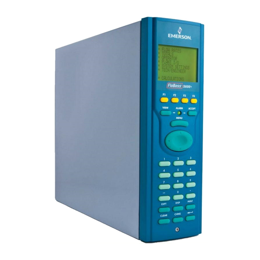
S600+ Instruction Manual A communications port on the bottom of the panel provides a way to directly connect to a PC. The front panel interface consists of a backlit LCD display, a 29-button keypad, and an alarm status LED (see Figure 1-4). -
Page 12: Config600 Lite
S600+ Instruction Manual Modbus. Modify display matrix. Config600 is a suite of software editors that enables you to monitor, configure, and calibrate the S600+. The software comes in three versions – Config600 Lite, Config600 Lite Plus, and Config600 Pro – with Config600 Pro being the most powerful version. -
Page 13: Config600 Pro
S600+ Instruction Manual Create a new application from base templates for gas, liquid, and prover applications. Edit process configuration data, including orifice size, analog input scaling, alarm limits, and keypad values. Build and customise Modbus slave maps, Modbus master polling sequences, front panel displays, and period report formats. -
Page 14: Additional Technical Information
S600+ Instruction Manual Additional Technical Information Refer to the following technical documents (available at www.EmersonProcess.com/Remote) for additional and most-current information. Table 1-1. Related Technical Information Name Form Number Part Number ™ S600+ D301151X412 FloBoss S600+ Flow Computer ™ Config600 D301164X012 Config600 Configuration Software ™... -
Page 15: Chapter 2 - Installation
S600+ Instruction Manual Chapter 2 – Installation In This Chapter Preparing for Installation ............... 2-1 Environmental Considerations .............. 2-2 Required Tools for Installation .............. 2-2 Installing the S600+ ................2-3 2.4.1 Unpacking the S600+ ............. 2-3 2.4.2 Removing the Front Panel ............. 2-3 2.4.3 Installing the Panel-Mounted Unit .......... -
Page 16: Environmental Considerations
S600+ Instruction Manual Figure 2-1. FloBoss S600+ System Components : User-supplied tools to assist in the installation process may Note include a Phillips screwdriver, a regular screwdriver, a small adjustable spanner wrench, and a 2.5mm Allen key. Environmental Considerations The S600+ panel mounted flow computer is designed for use within the control room. -
Page 17: Installing The S600
S600+ Instruction Manual 2.5 mm Allen key suitable for the hex cap screw on the front face of the front panel that secures the front panel molding to the case. Installing the S600+ Refer to the following procedures for installing the various S600+ components, including the front panel, panel-mounted unit, and modules. - Page 18 S600+ Instruction Manual Figure 2-3. Lifted Front Panel Disconnect the ribbon cable from the back of the front panel at the blue connector (refer to Figure 2-4). Observe the orientation of the connector with its mating keyway. You must correctly re-insert the ribbon cable at the end of the installation process.
- Page 19 S600+ Instruction Manual Disconnect Here Figure 2-4. Remove Connector Remove the top and bottom bosses from the unit housing, using a 5.5 mm (5 BA) hex wrench. Table 2-1. Mounting Dimensions Part Dimensions Display Keypad Molding 85 mm (3.35") width x 269 mm (10.59") height x 28 mm (1.10") deep Case 84.5 mm (3.327") width x 270 mm (10.63") height x 303.8 mm (11.94") deep...
-
Page 20: Installing The Panel-Mounted Unit
S600+ Instruction Manual Figure 2-5. Panel Mount Dimensions 2.4.3 Installing the Panel-Mounted Unit After removing the front panel, install the panel-mounted unit: Keeping environmental considerations in mind, construct the framework of the cubicle to support the operating panel. Note A standard 483 mm (19 in) rack that is 311 mm (12.25 in) high can accommodate up to four S600+s provided you support the rear of the case. - Page 21 S600+ Instruction Manual Figure 2-6. Panel Cutout Dimensions Note The S600+ fits into existing S500 and 869 flow computer panel cutouts. Ensure a panel thickness of at least 3 mm (0.12 in) to prevent distortion. If you use a thinner panel, support the rear of the case (refer to Figure 2-7).
-
Page 22: Reinstalling The Front Panel
S600+ Instruction Manual Place the front of the case against the rear of the prepared cutout. Re-install the top and bottom bosses and tighten with a 5.5 mm (5 BA) hex wrench. Once you have fitted the rear support, use a self-tapping screw to secure the case to the rear support. - Page 23 S600+ Instruction Manual Ejectors Figure 2-8. Unscrewing the Retention Screws Unlatch the ejectors for the appropriate module and pull the module clear of the case. You may need to rock the module slightly to release it from its connectors (refer to Figures 2-9 and 2-10). Figure 2-9.
-
Page 24: Installing Emc Protection
S600+ Instruction Manual Figure 2-10. Module Ready for Removal or Insertion Installation To install a module: Carefully align the module with the guides (located at the top and bottom of the case). Gently slide the module into the case until it seats fully with the appropriate connector on the backplane. - Page 25 S600+ Instruction Manual 2 M3 x 6mm screws (which secure the EMC backplate to the sides of the S600+ housing) 5 TY523 Ty-Rap self-locking cable fasteners (use as necessary to secure cables) These are standard components for a standard configuration. If Note your S600+ has a different configuration (for example, additional modules), you may have more components.
-
Page 26: Security Backplate In Place
S600+ Instruction Manual Figure 2-12. Security Backplate in Place In actual operation, the two right-most slots on the S600+ Note shown in Figure 2-12 would either contain modules or would be covered by blanking plates. Secure the backplate to the sides of the S600+ housing using the 2 M3 x 6mm screws. -
Page 27: Clamps On Cpu Module Power & Com Connections
S600+ Instruction Manual Medium ferrite clamp 25-way EMISTOP 37-way EMISTOP Large ferrite clamps Figure 2-14. Clamps on I/O Module Wiring Attach a large ferrite clamp onto the wiring to the CPU’s power connections and one medium clamp to the COM3 and COM 4 connections (see Figure 2-15). -
Page 28: Clamps On Cpu Module Com And Ethernet Connections
S600+ Instruction Manual Attach a medium ferrite clamp onto the wiring for COMs 5, 6, and 7 and a small ferrite clamp onto the Ethernet cable (see Figure 2- 16). Small ferrite clamp Medium ferrite clamp Figure 2-16. Clamps on CPU Module COM and Ethernet Connections This completes the installation process and provides the S600+ with EMC protection. -
Page 29: Chapter 3 - Cpu Module
S600+ Instruction Manual Chapter 3 – CPU Module In This Chapter CPU Module (P152) ................3-1 Power Supply ..................3-4 3.2.1 Watchdog Relay ..............3-4 3.2.2 On-Board Battery Backup ............3-4 Communication Ports ................. 3-5 3.3.1 RS-232 Serial Port ..............3-6 3.3.2 RS-422/RS-485 Multi-drop Port .......... -
Page 30: Port
S600+ Instruction Manual TB-1 Power First Ethernet port Second Ethernet port COM 4 COM 3 COM 5 COM 6 Note: You can configure COM 7 the A (–) terminal of COM 12 as a digital input Four additional RS-485 ports (COM 9 through COM 12) USB port Figure 3-1. - Page 31 S600+ Instruction Manual Figure 3-3. CPU Module Terminations P153 FRONT PANEL COMM - 1 SERVICE RJ-12 RESERVED FOR FRONT PANEL AND CONFIG 600 COMMS PC SETUP Figure 3-4. Front Panel Terminations Revised July-2017 CPU Module...
-
Page 32: Power Supply
S600+ Instruction Manual Power Supply The power connection is a plug-in, standard 5 mm pitch screw terminal block on the CPU module. The power supply connector is labeled TB- 1. Refer to Table 3-1 for the TB-1 pin connections. Power the S600+ using a nominal 30 Volts dc power source capable of supplying 2 Amps. -
Page 33: Communication Ports
S600+ Instruction Manual fully functional, the S600+ software routinely performs a regular load test on the unit. Replacing the Battery To replace the backup battery on the CPU module: Before beginning this process, ensure that any critical processes Note: the S600+ controls are otherwise managed. Power down the S600+. -
Page 34: Serial Port
S600+ Instruction Manual COM 9-12 The S600+ adds four new RS-485 serial ports (COM 9 through COM 12), located in the lower half of the CPU module (see Figure 3-1). Table 3-3. Communication Ports Communications Port Backplate Descriptor Description Network 1 NTWK1 Ethernet Network 2... -
Page 35: Rs-422/Rs-485 Multi-Drop Port
S600+ Instruction Manual The maximum cable length is a function of the baud rate and quality of cable used. For example, a maximum length of 15 m (50 ft) should be used at 19200 bps when using unscreened cable. Connect ports to the peripheral devices using multi-conductor, shielded cable not longer than 8 meters (approx. -
Page 36: Local Operator Pc Or Remote Display Port
S600+ Instruction Manual : There is only one gateway, which is available through the Note ENET0 port. If the destination IP is outside of the network, then the packet goes to the gateway for transmission outside of the network. If the gateway is on the same network as the end devices, usually one end or the other of the IP address is 0 or 255. -
Page 37: Cpu Connectors And Jumpers
S600+ Instruction Manual CPU Connectors and Jumpers Table 3-6 shows the connectors and jumpers on the CPU module. This information is for identification purposes only. Do not modify these settings, unless told to do so by the factory. : The position values shown in boldface are the default Note configuration settings, which may not apply to your specific configuration. -
Page 38: Additional Technical Information
S600+ Instruction Manual Additional Technical Information Refer to the following technical documentation (available at www.EmersonProcess.com/Remote) for additional and most-current information. Table 3-7. I/O Module Technical Specifications Name Form Number Part Number FloBoss™ S600+ Flow Computer S600+ D301151X412 3-10 CPU Module Revised July-2017... -
Page 39: Chapter 4 - Input/Output (I/O)
S600+ Instruction Manual Chapter 4 – Input/Output (I/O) In This Chapter I/O Module (P144) ................4-1 4.1.1 Analogue Inputs (ANIN) ............4-3 4.1.2 Analogue Outputs (DAC) ............4-5 4.1.3 Digital Inputs (DIGIN)............. 4-6 4.1.4 Digital Outputs (DIGOUT) ............4-8 4.1.5 Turbine Pulse Inputs .............. -
Page 40: Anin
S600+ Instruction Manual For field wiring, the module provides three low-density D-type connectors: SKT-A, SKT-B, and SKT-C (refer to Figure 4-1). SKT-A ANIN 1-10 ANOUT 1-4 SKT-B ANIN 11-12 DIGIN 1-6 DIGOUT 1-2 Freq Inputs Pulse Outputs SKT-C DIGIN 7-16 DIGOUT 3-12 Turbine Inputs Figure 4-1. -
Page 41: Analogue Inputs (Anin)
S600+ Instruction Manual I/O MODULE (P144) SERVICE SERVICE SKT A SKT A +15V SUPPLY ADC 1+ DAC 1 OUTPUT ADC 2+ GROUND ADC 3+ +15V +15V 1 - 5 V 1 - 5 V SUPPLY ADC 4+ DAC 2 OUTPUT ADC 5+ GROUND +15V... -
Page 42: Analogue Input Schematic
S600+ Instruction Manual The primary measurement for ANIN 1-10 is voltage, which is compared to a stable reference source. The channels are configurable to current using a bit link (jumper) on the module to place a high accuracy calibrated shunt resistor in parallel with the input. Refer to Figures 4-4 and 4-5. -
Page 43: Analogue Outputs (Dac)
S600+ Instruction Manual Table 4-1. ANIN Pin Connections for SKT-A Function ANIN-CH1 ANIN-CH2 ANIN-CH3 ANIN-CH4 ANIN-CH5 RETURN CH1-5 ANIN-CH6 ANIN-CH7 ANIN-CH8 ANIN-CH9 ANIN-CH10 RETURN CH6-10 Table 4-2. ANIN Pin Connections for SKT-B Function ANIN-CH11 (current) ANIN-CH12 (current) 4.1.2 Analogue Outputs (DAC) The S600+ supports four analogue outputs (D/A Converter). -
Page 44: Digital Inputs (Digin)
S600+ Instruction Manual Figure 4-7. Analogue Output Schematic (Externally Powered Device) Figure 4-8. Analogue Output Schematic (Externally Powered through S600+) Table 4-3. D/A Converter Output Pin Connections for SKT-A Function DAC-CH1 +15 V SOURCE DAC-CH1 SINK DAC-CH1 0 VDC DAC-CH2 +15 V SOURCE DAC-CH2 SINK DAC-CH2 0 VDC DAC-CH3 +15 V SOURCE... -
Page 45: Digital Input Schematic (Open Collector Device)
S600+ Instruction Manual : You must connect the feed lines (such as pin 17 on SKT-B) to a Note 24 Volts dc source. The DIGIN lines (such as pin 13 on SKT- B) expect typical “open collector” (referenced to GND) connections. -
Page 46: Digital Outputs (Digout)
S600+ Instruction Manual Table 4-5. DIGIN Pin Connections for SKT-C Function DIGIN-CH7 DIGIN-CH8 RETURN CH5-8 DIGIN-CH9 DIGIN-CH10 DIGIN-CH11 DIGIN-CH12 RETURN CH9-12 DIGIN-CH13 DIGIN-CH14 DIGIN-CH15 DIGIN-CH16 RETURN CH13-16 4.1.4 Digital Outputs (DIGOUT) The S600+ supports 12 digital output (DIGOUT) channels, which are open collector type outputs. -
Page 47: Turbine Pulse Inputs
S600+ Instruction Manual Table 4-6. DIGOUT Pin Connections for SKT-B Function DIGOUT-CH1 DIGOUT-CH2 Table 4-7. DIGOUT Pin Connections for SKT-C Function DIGOUT-CH3 DIGOUT-CH4 RETURN CH1-4 DIGOUT-CH5 DIGOUT-CH6 DIGOUT-CH7 DIGOUT-CH8 RETURN CH5-8 DIGOUT-CH9 DIGOUT-CH10 DIGOUT-CH11 DIGOUT-CH12 RETURN CH9-12 4.1.5 Turbine Pulse Inputs With the optional mezzanine module (P148) for pulse inputs installed, the I/O module supports four pulse inputs either independently or as two pairs (“dual pulse mode”). -
Page 48: Pulse Outputs (Pulseout)
S600+ Instruction Manual Figure 4-13. Pulse Input Schematic (with 12 V P148 Mezzanine Module) Figure 4-14. Pulse Input Schematic (with 24 V P148 Mezzanine Module) Table 4-8. Dual Pulse Input Pin Connections for SKT-C Function SINGLE/DUAL PULSE-CH1+ SINGLE/DUAL PULSE-CH1- SINGLE/DUAL PULSE-CH2+ SINGLE/DUAL PULSE-CH2- SINGLE/DUAL PULSE-CH3+ SINGLE/DUAL PULSE-CH3-... -
Page 49: Raw Pulse Output (Rawout)
S600+ Instruction Manual Table 4-9. PULSEOUT Pin Connections for SKT-B Function PULSEOUT-CH1 PULSEOUT-CH2 PULSEOUT-CH3 PULSEOUT-CH4 RETURN CH1-4 PULSEOUT-CH5 RETURN CH5 4.1.7 Raw Pulse Output (RAWOUT) The S600+ supports a single raw pulse output, typically used in prover applications to mimic the turbine signals and send them to the prover mezzanine card. -
Page 50: Frequency Inputs
S600+ Instruction Manual Table 4-10. Raw Pulse Output Pin Connections for SKT-C Function Raw Output Return 4.1.8 Frequency Inputs The S600+ typically uses the three supported frequency inputs for density transducer signals. Each input has an input range of 0 to 10 KHz. -
Page 51: Prt/Rtd Inputs
S600+ Instruction Manual Table 4-11. Frequency Input Pin Connections for SKT-B Function FREQUENCY-CH1+ FREQUENCY-CH1- FREQUENCY-CH2+ FREQUENCY-CH2- FREQUENCY-CH3+ FREQUENCY-CH3- 4.1.9 PRT/RTD Inputs The S600+ supports three Platinum Resistance Thermometer (PRT)/Resistance Temperature Detector (RTD) inputs. These inputs are suitable for Class A, 4-wire PRT devices that conform to the BS EN 60751:1996 standard. -
Page 52: Jumper Settings
S600+ Instruction Manual Table 4-12. PRT/PRD Input Pin Connections for SKT-B Function PRT-CH1 I+ PRT-CH1 V+ PRT-CH1 V- PRT-CH1 I- PRT-CH2 I+ PRT-CH2 V+ PRT-CH2 V- PRT-CH2 I- PRT-CH3 I+ PRT-CH3 V+ PRT-CH3 V- PRT-CH3 I- 4.1.10 Jumper Settings The boldface entries in the Position column on Table 4-13 are the default configuration settings. -
Page 53: I/O
S600+ Instruction Manual Table 4-13. I/O Module Jumper Settings Jumper Position Descriptions Flash Flash Write Enable Flash Write Protected Node Address (see Table 4-14) Point to Point mode enabled Point to Point mode disabled LK3 – LK10 Multiplex (MUX) Addresses – see Table 4-14 Communications Mode –... -
Page 54: Prover Module (P154)
S600+ Instruction Manual Table 4-14. Multiplex Mode Addressing Address LK10 Comment Not a valid address First or only board Second board Not a valid address Prover Module (P154) The dedicated Prover interface module (P154) has been designed to work with compact or small-volume provers; unidirectional provers; bi-directional provers;... - Page 55 S600+ Instruction Manual Figure 4-20. Prover Module (P154) Figure 4-21. Prover Module Revised July-2017 4-17...
-
Page 56: Digital Inputs (Digin)
S600+ Instruction Manual SERVICE SERVICE SKT D SKT D DETECTOR SWITCH 1 - RAW PULSE + SWITCH 2 - INPUT 1 - RAW PULSE + SWITCH 3 - INPUT 2 - SWITCH 4 - +24V RAW PULSE + COMMON + VE INPUT 3 - PIM LOOP + - OUTPUT... -
Page 57: Digital Input Schematic (Open Collector Device)
S600+ Instruction Manual : You must connect the return lines (such as pin 17 on SKT-E) to Note a 24 Volts dc source. The DIGIN lines (such as pin 13 on SKT- E) expect typical “open collector” (referenced to GND) connections. -
Page 58: Digital Outputs (Digout)
S600+ Instruction Manual Function DIGIN CH-30 DIGIN CH-31 DIGIN CH-32 RETURN CH 29-32 Table 4-16. DIGIN Pin Connections for SKT-F Function DIGIN-CH7 DIGIN-CH8 RETURN CH5-8 DIGIN-CH9 DIGIN-CH10 DIGIN-CH11 DIGIN-CH12 RETURN CH9-12 DIGIN-CH13 DIGIN-CH14 DIGIN-CH15 DIGIN-CH16 RETURN CH13-16 4.2.2 Digital Outputs (DIGOUT) Each Prover module provides 12 digital output (DIGOUT) high current, open collector type channels. -
Page 59: Turbine Pulse Inputs
S600+ Instruction Manual Figure 4-26. Digital Output Schematic (24 V Switched Indicator) Table 4-17. DIGOUT Pin Connections for SKT-E Function DIGOUT-CH1 DIGOUT-CH2 Table 4-18. DIGOUT Pin Connections for SKT-F Function DIGOUT-CH3 DIGOUT-CH4 RETURN CH1-4 DIGOUT-CH5 DIGOUT-CH6 DIGOUT-CH7 DIGOUT-CH8 RETURN CH5-8 DIGOUT-CH9 DIGOUT-CH10 DIGOUT-CH11... -
Page 60: Pulse Outputs (Pulseout)
S600+ Instruction Manual Figure 4-27. Pulse Input Schematic (with 24 V P148 Mezzanine Module) Table 4-19. Dual-Pulse Input Pin Connections for SKT-F Function DUAL PULSE-CH1+ DUAL PULSE-CH1- DUAL PULSE-CH2+ DUAL PULSE-CH2- DUAL PULSE-CH3+ DUAL PULSE-CH3- DUAL PULSE-CH4+ DUAL PULSE-CH4- 4.2.4 Pulse Outputs (PULSEOUT) The S600+ provides four programmable pulse outputs, typically used for electronic counters. -
Page 61: Frequency Input Schematic (Without Is Barrier And Dc-Coupled)
S600+ Instruction Manual Table 4-21 shows the frequency input pin connections. Refer to Figures 4-29 and 4-30 for field wiring schematics. : The Micro Motion (previously Solartron) devices shown in Note Figures 4-29 and 4-30 may still have their previous manufacturer’s labels. -
Page 62: Jumper Settings
S600+ Instruction Manual 4.2.6 Jumper Settings The boldface entries in the Position column on Table 4-22 are the default configuration settings. They may not apply to your specific configuration. Table 4-22. Prover Module Jumper Settings Jumper Position Descriptions Flash Write Enable Write Protected Node Address (see Table 4-23) Multiplexed mode (MUX) -
Page 63: Hart Module (P188)
S600+ Instruction Manual HART Module (P188) A 12-channel I/O module provides communications between Highway ® Addressable Remote Transducer (HART ) devices and the S600+. Each digital input channel is capable of handling up to 8 devices (up to a maximum of 50 transmitters for the HART module). The S600+ supports point-to-point, multi-drop, and dual master architectures. -
Page 64: Hart Pin Connections (Socket B)
S600+ Instruction Manual Socket A Socket A Channel Number Pin Number Channel 5+ Channel 5- Channel 6+ Channel 6- Channel 7+ Channel 7- Channel 8+ Channel 8- Table 4-25. HART Pin Connections (Socket B) Socket B Socket B Channel Number Pin Number Channel 9+ Channel 9-... -
Page 65: Mezzanine Module (P148)
S600+ Instruction Manual Figure 4-33. HART Device and Handheld Communicator Beyond the IS Barrier Figure 4-34. HART Device without Handheld Communicator Mezzanine Module (P148) The mezzanine module (P148) can be fitted to the Prover or the I/O module (see Figure 4-2), and provides pulse inputs. When used on the I/O module, it affects pulses 1 and 4;... - Page 66 S600+ Instruction Manual [This page is intentionally left blank.] 4-28 Revised July-2017...
-
Page 67: Chapter 5 - Front Panel
S600+ Instruction Manual Chapter 5 – Front Panel In This Chapter Description ..................5-1 Front Panel Port .................. 5-2 Keypad ....................5-2 5.3.1 Function Keys (F1 - F4) ............5-2 5.3.2 Direction and Menu Keys ............5-3 5.3.3 Numeric Keys ................ 5-3 5.3.4 Operation Keys .............. -
Page 68: Front Panel Port
S600+ Instruction Manual Front Panel Port The front panel port, located on the bottom of the front panel, is the primary connection for the Config600 software program to use when transferring configuration files. The port requires a six-pin RJ-12 connector (part number 3080017) for RS-232 (RS-232D) communications (see Figure 5-2). -
Page 69: Direction And Menu Keys
S600+ Instruction Manual 5.3.2 Direction and Menu Keys The large, oval, four-direction arrow key is located just below the MENU key (see Figure 5-1). Note the directional arrows (, , , and ) in the surface of the four-direction key. Pressing these arrows allows you to navigate the display matrix and select parameters or data items to view or change. -
Page 70: Alarm Led And Alarm Keys
S600+ Instruction Manual 5.3.5 Alarm LED and Alarm Keys Located between the F keys and the MENU key on the keypad is the Alarm LED and two alarm-related keys, VIEW and ACCEPT. During normal operations (with no alarms activated), the Alarm LED is constantly green. -
Page 71: Editable Value
S600+ Instruction Manual 6* TECH/ENGINEER 8* CALCULATIONS Figure 5-3. S600+ Main Menu The S600+ uses all eight lines of the display to show the available menu options, which are arranged in a hierarchy of menus and submenus. Each item on menus and associated submenus is numbered, which enables you to select menu items using the numeric keys on the keypad. -
Page 72: Navigating The Displays
S600+ Instruction Manual The data page in this location would have the page reference number 3.4 (third row, fourth display) 20.1 would then be the first display page on the 20 row. You can use the DISP operation key to quickly access that display (see Section 5.5.1. -
Page 73: S600+ Main Menu
S600+ Instruction Manual 5* SYSTEM SETTINGS 6* TECH/ENGINEER 8* CALCULATIONS Figure 5-6. S600+ Main Menu Sub-menus (as shown in Figure 5-7) may either have an asterisk or a period after the option number. A period indicates that option accesses a data page. 1. -
Page 74: Disp Key
S600+ Instruction Manual 9.45 Sm3/h Initial data page address P2.1 <of 2>--------- FLOW RATE STR01 MASS FR 12.01 Adjacent data page address P3.1 <of 2>--------- Figure 5-9. Moving between Data Pages If we relate this action back to our display page table, we can see that these are adjacent screens: 5.5.1 DISP Key Since each data page has a unique page reference number, you can use... -
Page 75: Menu Hierarchy
S600+ Instruction Manual 5.5.3 Menu Hierarchy Refer to Appendix B for information on the menus and sub-menus in the S600+, as well as more information on navigating the front panel display screens. 5.5.4 Security Codes Changing options and display values (as well as some operations at the front panel display) require that you enter a security code. -
Page 76: Changing A Display Value
S600+ Instruction Manual Press a numeric key to select a value. The left-hand screen in Figure 5-11 displays. Press a numeric key to confirm the selected value. The right-hand screen in Figure 5-11 displays, showing the new value. CONFIRM STR01 DENS SELECT SET TO: Status: 1. -
Page 77: Changing A Calculation Mode
S600+ Instruction Manual Press Return. The S600+ accepts the new value and displays it as shown on the right-hand screen in Figure 5-13. CURRENT VALUE: ADCO2 100.000 ! I/O01 ADC 02 NO ENTRY LIMITS: Keypad Value: 99.999 Measured Value: ENTER NEW VALUE: -24.998 99.999 P27.2 <of... -
Page 78: Assigning A Page To A Function (F) Key
S600+ Instruction Manual To define the default display: Go to the required data display page. Press Minus. Press Minus again to confirm the selection. To clear the default display, go to a menu page and repeat steps 2 and 3. To invoke the default display, use the CLEAR key. : The CLEAR key does not work while in Edit mode. -
Page 79: Using The Print Key
S600+ Instruction Manual 5.12 Using the Print Key By default, the S600+ is configured to output reports to a serial printer or a terminal. The S600+ also outputs reports to its internal webserver (see Chapter 6, Webserver Access). When you press PRINT, the Print Options menu displays: PRINT OPTIONS---- 1. -
Page 80: Enabling Usb
S600+ Instruction Manual Select a report based on the following options: Option Sub Reports Configuration 1 Constant Log TXT 2 Constant Log CSV 3 Display Dump 4 Security Dump 5 All Alarms Reports 1 Current Report 2 Config Report 3 Archived Reports Communications 1 Modbus Maps Current Alarms... -
Page 81: Usb Report Control Menu
S600+ Instruction Manual 1* FLOW RATES 1. DISPLAY SETUP USB REPORT CTL 2* TOTALS 2. CONTRAST 3* OPERATOR 3. DATE & TIME Status: 4* PLANT I/O 4. DISPLAY TEST IDLE 5* SYSTEM SETTINGS 5. SECURITY 6* TECH/ENGINEER 6* COMMUNICATIONS 7. USB 8* CALCULATIONS P204.1 <of 4>... -
Page 82: Selecting A Configuration
S600+ Instruction Manual Press 1 to confirm your selection. As the report export proceeds, the USB Report Progress screen shows the percentage of completion. Removing the USB flash drive while the report dump is in progress Warning may result in file corruption. Remove the flash drive only after the status of the USB Report Control screen returns to IDLE. - Page 83 S600+ Instruction Manual : If you select an option number that is “empty” (does not Note have an associated configuration), the S600+ ignores the choice and redisplays the Cold Start menu. Revised July-2017 Front Panel 5-17...
- Page 84 S600+ Instruction Manual [This page is intentionally left blank.] 5-18 Front Panel Revised July-2017...
-
Page 85: Chapter 6 - Webserver Access
S600+ Instruction Manual Chapter 6 – Webserver Access In This Chapter Defining Webserver Access ............... 6-1 Accessing the S600+ ................6-2 Navigating the Webserver Interface ........... 6-5 The S600+ has an embedded webserver, which enables you to access reports, displays, and diagnostics through the Internet. The number of items available for viewing or modification depends on your defined security access level (see Section 6.1). -
Page 86: Accessing The S600
S600+ Instruction Manual Figure 6-1. PCSetup Webserver Access For further information on using this screen, refer to Chapter 7, Advanced Setup Configuration, in the Config600 Software User Manual (part D301220X412). Once you complete this security level-access matrix, you can access the S600+’s webserver over a TCP/IP connection. - Page 87 S600+ Instruction Manual Type the IP address of the S600+ in the browser’s URL address bar (in the format http://nnn.nnn.nnn.nnn) and press Enter. Note If encryption has been enabled on the webserver (see Chapter 5, Section 5.15, Enabling Encryption), you must type the IP address in the format https://nnn.nnn.nnn.nnn (where https indicates a secure server).
-
Page 88: Hierarchy Menu
S600+ Instruction Manual Hierarchy Menu Menu Bar Report display area Figure 6-2. Initial Webserver Access You then navigate through the displays using the selections on the screen’s menu bar (see Table 6-1). : The options on the hierarchy menu change as you select options Note from the menu bar. -
Page 89: Navigating The Webserver Interface
S600+ Instruction Manual Navigating the Webserver Interface The webserver interface allows you to view reports and data from the front panel display screens. Depending on your security level, you may also be able to change values and navigate through the interface using two navigation bars. -
Page 90: Alarm Archive
S600+ Instruction Manual When you select an option from the menu bar, a hierarchy tree menu appears on the left side of the browser. Use the hierarchy menu to specify the content that appears in the display area. CSV Button The S600+ web interface typically displays content as a text file (as shown in Figure 6-5). - Page 91 S600+ Instruction Manual Log Off Figure 6-6. Example Alarms Screen To close a screen, select another element from the menu bar or another screen from the hierarchy menu. To close the webserver access link, select the Log Off option in the menu bar and close the browser. The caching mechanism on many Internet browser applications may Caution present a security challenge.
- Page 92 S600+ Instruction Manual [This page is intentionally left blank.] Webserver Access Revised July-2017...
-
Page 93: Chapter 7 - Startup
S600+ Instruction Manual Chapter 7 – Startup In This Chapter Starting the S600+ ................7-1 Warm Start ..................7-1 Cold Start ..................7-2 7.3.1 Initiating a Cold Start ............. 7-2 Startup Menu ..................7-3 7.4.1 Network Setup ............... 7-4 Messages ..................7-7 This chapter describes procedures for starting and restarting the S600+. -
Page 94: Cold Start
S600+ Instruction Manual Cold Start During a cold start, the S600+ copies the configuration file from flash memory and replaces any online changes that have been made to the configuration files either since the last ones downloaded from a PC running Config600 software or since the last backup. -
Page 95: Startup Menu
S600+ Instruction Manual Enter Code Key in your security code when the prompt displays. Press 1 to select COLD ST, and press 1 again to confirm the SYSTEM RESTARTING – selection. The S600+ displays a PLEASE WAIT message. The S600+ then performs a reset, which concludes when the Startup menu appears. -
Page 96: Network Setup
S600+ Instruction Manual Option Description Reflash Firmware Reprograms the S600+ operating system firmware stored in Flash memory (see Chapter 8, Troubleshooting). Factory Setup Clears SRAM and formats Flash memory and changes additional settings. Note: Use this option only at the direction of a factory representative. - Page 97 S600+ Instruction Manual 1. TCP/IP ADDRESS 1 2. GATEWAY ADDRESS 1 3. SUBNET MASK 1 4. TCP/IP MODE 5. GO BACK Figure 7-4. Network Definition Menu Select TCP/IP ADDRESS 1. The system prompts you to enter a valid TCP/IP address. Enter an address and press Enter.
-
Page 98: Modbus Screen
S600+ Instruction Manual S600 ENTER NEW MODBUS ADDRESS (1...247) CURRENT 00001 Figure 7-5. Modbus Screen Enter the address value (any value between 1 and 247). If you change the Modbus address, you must restart the S600+ in order for the change to take place. PC Comms Use this option to define serial port connection characteristics : If you are using an Ethernet connection, you do not need to... -
Page 99: Messages
S600+ Instruction Manual Messages During warm or cold starts the S600+ can display various messages. These include: Message Meaning REFLASH DISABLED Firmware write protect is enabled. To resolve: From the Cold Start menu, select FACTORY SETUP > FIRMWARE LOCK. You can then disable the firmware write protect. - Page 100 S600+ Instruction Manual Message Meaning SYSTEM IS BEING A configuration file is being downloaded to CONFIGURED the S600+. EXTERNALLY PLEASE WAIT. SYSTEM A reboot is in progress. RESTARTING PLEASE WAIT. Startup Revised July-2017...
-
Page 101: Chapter 8 - Troubleshooting
S600+ Instruction Manual Chapter 8 – Troubleshooting In This Chapter Guidelines ..................8-1 Checklists ..................8-2 8.2.1 Power Issues ................ 8-2 8.2.2 Startup Menu ................ 8-2 8.2.3 Front Panel Lighting ............. 8-2 8.2.4 Front Panel LED..............8-2 8.2.5 I/O LED ................8-3 8.2.6 I/O Fail Messages .............. -
Page 102: Checklists
S600+ Instruction Manual Checklists This section provides a series of checkpoints for frequent issues. 8.2.1 Power Issues If you are experiencing trouble with powering up the S600+: Check the wiring connections at terminal block TB1 on the CPU backplate and the wiring at the power source. ... -
Page 103: I/O Led
S600+ Instruction Manual : The LED is orange while at the Startup menu. If it is still Note orange when the configuration is running, contact your local sales representative or technical support. 8.2.5 I/O LED If the red or green LEDs on the backplate of the I/O module do not blink while the S600+ is operating: ... -
Page 104: Reflash Firmware
S600+ Instruction Manual 8.3.1 Reflash Firmware Using this procedure, you can reprogram the S600+’s flash memory with new values for the operating system components and the application firmware. Under no circumstances should you turn off the S600+ while it is erasing or Caution reprogramming the Flash memory. -
Page 105: Clear Sram
S600+ Instruction Manual To reflash the configuration data file: Select Transfer Data from the Config600 software. Choose the Comm port connected to the S600+. Default parameters for serial ports are 38400 bps, 8 data bits, 1 stop bit, and no parity. : You can also transfer configuration files using the Ethernet Note connection, as well as the serial communications port. -
Page 106: Changing The Fuse
S600+ Instruction Manual 8.3.4 Changing the Fuse The fuse is located in a clip-in type holder on the CPU module (see Figure 8-1): Fuse Figure 8-1. Fuse Location To change a fuse: Switch off the power supply. Remove any connections. Unscrew and remove the CPU module from the S600+ case. -
Page 107: Appendix A - Glossary
S600+ Instruction Manual Appendix A – Glossary This is a generalised glossary of terms. Not all the terms may Note necessarily correspond to the particular device or software described in this manual. For that reason, the term “ROC” identifies all varieties of remote operations controllers and flow computers (including ROC800-Series, ROC800L, ™... - Page 108 S600+ Instruction Manual Binary Numbers in base 2 (that is, only numbers 0 and 1 are used). May be represented as a digital signal and referred to as True/False, High/Low, or On/Off. A binary digit, either a binary 0 or 1. One byte is the amount of memory needed to store each character of information (text or numbers).
-
Page 109: Flash Memory
S600+ Instruction Manual Data Concentrator Unit. Used to connect one device (such as a printer) to multiple S600s. Control of the shared device is determined by the hardware handshaking lines of the RS-232 port. Densitometer Transducer used to measure the density of the product at current conditions in the pipework where it is mounted. -
Page 110: Holding Register
S600+ Instruction Manual ® HART Highway Addressable Remote Transducer (or HART) is a communication protocol designed for industrial process measurement and control applications. It combines both analogue and digital communication and can communicate a single variable using a 4-20 mA analogue signal, while also communicating added information on a digital signal. -
Page 111: Non-Volatile Memory
S600+ Instruction Manual Modem Modulator Demodulator; a device used to communicate with other equipment using a telephone network. Modulate Superimposing one signal upon another. Motor Operated Valve; a valve that is motorized and requires a signal to drive the valve open, a signal to drive the valve closed, and has a two signals returning to the S600 to describe the valve as being open, closed, moving, or illegal. -
Page 112: Security Code
S600+ Instruction Manual reference temperature (for example, relative density 15/15°C). [Source API Vocabulary 1994]. Gas relative density: As above except that air is used as the reference instead of water. Ideal and Real gas relative density. See Specific Gravity. Note: Water at 15°C is 999.058 kg/m3. Water at 60°F is 999.012 kg/m3. -
Page 113: Tri-Reg
S600+ Instruction Manual Averaging time and flow. Totaliser Area of RAM for integrating totals. Transducer Device that converts energy from one state to another. TRI-REG Triple register; an area of RAM where data is stored in triplicate, normally used to store totals. - Page 114 S600+ Instruction Manual [This page is intentionally left blank.] Glossary Revised July-2017...
- Page 115 S600+ Instruction Manual Appendix B – Front Panel Navigation In This Chapter Man Menu ...................B-2 Rates Menu ..................B-2 Totals Menu ..................B-3 Operator Menu ..................B-4 Plant I/O Menu ..................B-5 System Settings Menu ................B-5 Tech/Engineer Menu ................B-6 Calculations Menu ................B-7 This appendix describes the default menu options of the S600+ front panel display.
-
Page 116: Appendix B - Front Panel Navigation
S600+ Instruction Manual B.1 Main Menu Once startup completes, the Main menu displays: Main Menu 1* FLOW RATES 2* TOTALS 3* OPERATOR 4* PLANT I/O 5* SYSTEM SETTINGS 6* TECH/ENGINEER 8* CALCULATIONS B.2 Flow Rates Menu The system uses all the parameters in this group to calculate the various flow rates. -
Page 117: Totals Menu
S600+ Instruction Manual B.3 Totals Menu The system uses all parameters in this group in calculating the various totals. If one of the streams is a prover, the stream does not appear on this menu. Main > Totals Menu 1* STATION 2* STATION 3* STREAM 4* STREAM... -
Page 118: Operator Menu
S600+ Instruction Manual B.4 Operator Menu The parameters in this group are values and statuses you typically want to view when monitoring the operation of the S600+. : AVE T&P refers to the average temperature and pressure Note parameters. STAT&CTRL refers to status and control parameters. -
Page 119: Plant I/O Menu
S600+ Instruction Manual B.5 Plant I/O Menu The parameters in this group are the values, limits, and status of the field I/O. Main > Plant I/O Menu 1* ANALOG INPUTS 2* PRT/RTD INPUTS 3* HART INPUTS 4* FREQUENCY INPUTS 5* PULSE INPUTS 6* DIGITAL I/OS 8 Next 1 Previous... -
Page 120: Tech/Engineer Menu
S600+ Instruction Manual B.7 Tech/Engineer Menu The parameters in this group are for advanced users or factory personnel. The Date & Time menu option sets the format for reporting the date and time. The Security menu option sets the security parameters. -
Page 121: Calculations Menu
S600+ Instruction Manual B.8 Calculations Menu The parameters in this group are all used in and result from system calculations and are further subgrouped as parameters relating to the values going into the calculations (as input) and results of the calculations (as output). - Page 122 S600+ Instruction Manual [This page is intentionally left blank.] Front Panel Navigation Revised July-2017...
-
Page 123: Appendix C - Chromatographs
S600+ Instruction Manual Appendix C – Chromatographs In This Chapter Station/Stream Assignment ..............C-1 C.1.1 Single Metering Stream with No Station ....... C-2 C.1.2 Multiple Metering Streams Assigned to a Common Station ................... C-2 C.1.3 Individual Metering Streams Assigned to a Chromatograph .............. -
Page 124: Station/Stream Assignment
S600+ Instruction Manual Siemens Generic (user-configurable) Note: This software does not currently support a paycheck chromatograph. C.1 Station/Stream Assignment The S600 chromatograph software supports the following station and metering stream combinations: Single stream with no station Multiple metering streams assigned to a common station (where each stream uses the station’s mole percentage set) ... -
Page 125: Multiple Metering Streams Separately Assigned To A Stream
S600+ Instruction Manual Mode Handling The individual stream RD and CV modes (provided they are in “keypad” or “chromat” mode) can track the individual stream mole % Note selection (keypad or chromat). C.1.4 Multiple Metering Streams Separately Assigned to a Stream In this situation, a station-to-chromatograph link exists but the chromatograph is configured to analyse a number of cycle streams where these streams may be assigned to separate metering streams in... -
Page 126: Main Setup Parameters
S600+ Instruction Manual C.2.1 Main Setup Parameters Combination Type Keypad set only /single chromatograph Split Switch None/C6+/C7+/C8+/C9+/C10+ Disable/enable mole percentage range alarm Range Checks handling Disable/enable mole percentage deviation Deviation Checks checking Critical Checks Disable/enable critical alarms checks Non Critical Checks Disable/enable non-critical alarms checks Failure Revert Keypad/last good set revisions upon failure... -
Page 127: Telemetry Outputs
S600+ Instruction Manual Matched Reset Delay Indicates the interval after receipt of a matched report before resetting the new data flag Unmatched Reset Indicates the delay the system takes before Delay resetting the new data flag after the flag is seen as set but the report cycle stream does not match the S600+. -
Page 128: Configuration Type: Keypad Mole Percentage Set Only
S600+ Instruction Manual Raw Mole %s Updated from a successful telemetry poll Raw CV (etc.) Updated from a successful telemetry poll Latest Mole %s Adjusted/normalised from latest report Last Good Mole % Adjusted/normalised from latest report Raw Alarms Register Detailed indication of global alarms Codes Request Flag Trigger for Modbus master telemetry module Component Codes... -
Page 129: Configuration Type: 2551/2350 Euro
S600+ Instruction Manual If the keypad set is valid, the system normalises it and then copies it to the in-use set If the keypad set is invalid, an alarm is raised and the in-use set remains intact. C.4 Configuration Type: 2551/2350 Euro For this configuration, use PCSetup to preconfigure the master Modbus interface. - Page 130 S600+ Instruction Manual Stage Description Wait for Status Data Reply Wait up to the time-out period for the 2551 to respond. If no reply has been received then set the telemetry fail alarm and set the stage to Idle. If a reply has been received and the new report available flag is set and the report stream matches the S600+ cycle stream, then set the stage to Pre-component...
- Page 131 S600+ Instruction Manual Stage Description Wait for RD & CV Poll Wait up to the time-out period for the Reply 2551 to respond. If no reply has been received, then set the telemetry fail alarm and set the stage to Idle. If a reply has been received, then set the next stage to Pre-status Poll Delay (2).
- Page 132 S600+ Instruction Manual Stage Description Wait for Status Data Reply Wait up to the time-out period for the 2551 to respond. If no reply has been received, then set the telemetry fail alarm and set the stage to Idle. If a reply has been received and the new report available flag is still set and the report stream still matches the S600+ cycle stream, then set the stage to Pre-...
-
Page 133: Determining The Mole Percentage Set
S600+ Instruction Manual C.4.2 Determining the Mole Percentage Set This section details how the module selects the mole percentage set. Refer to Section C.3, Configuration Type: Keypad Mole Percentage Keypad Set Only, for information on setting the keypad percentage set. Set Selected The system uses the following logic to select a chromatograph set: Chromatograph... -
Page 134: Telemetry Stages
S600+ Instruction Manual C.5.1 Telemetry Stages Data acquisition occurs over a number of stages, during which the data handling module interacts with the Modbus master module to control the order of telemetry polling. The 2251 may enter a phase in which it is busy printing report and does not respond to poll requests. -
Page 135: Determining The Mole Percentage Set
S600+ Instruction Manual Stage Description Wait for RD and CV Poll Wait up to the time-out period for the Reply 2251 to respond. If no reply has been received, then set the telemetry fail alarm and set the stage to Idle. If a reply has been received, then proceed to Process the Analysis Report. -
Page 136: Handling Operator Commands
S600+ Instruction Manual C.5.3 Handling Operator Commands This section details how the module handles operator commands. Select the keypad set only if it is valid according to the checks outlined Select Keypad Mole in Section C.4.2, Determining the Mole Percentage Set. Otherwise, Percentage leave the in-use set intact. - Page 137 S600+ Instruction Manual Stage Description Wait for Status or Pre- Wait up to the time-out period for the unit Analysis Reply to respond and then (depending on the data being polled for) either: Process the staus report checcking for any critical alarms, if any alarms are found then raise the alarms.
-
Page 138: Determining The Mole Percentage Set
S600+ Instruction Manual Stage Description Process Data Process the analysis data: 1. Reorder the raw telemetered mole percentage into S600+ internal order (as directed by the received component codes, which run in ascending values from 100). 2. If configured to do so, check low/high and deduction limits. -
Page 139: Handling Operator Commands
S600+ Instruction Manual C.6.3 Handling Operator Commands This section details how the module handles operator commands. Select the keypad set only if it is valid according to the checks outlined Select Keypad Mole in Section C.4.2, Determining the Mole Percentage Set. Otherwise, Percentage leave the in-use set intact. - Page 140 S600+ Instruction Manual Stage Description Poll for Status Data Wait up to the time-out period for the unit to respond and then (depending on the data being polled for) either: Process the status report and, if there is a new report, issue a new poll to request the mole data and set the next stage to be Poll for Mole Percentages...
-
Page 141: Determining The Mole Percentage Set
S600+ Instruction Manual Stage Description Process Data Process the analysis data: 1. Reorder the raw telemetered mole percentage into S600+ internal order (as directed by the received component codes, which run in ascending values from 100). 2. If configured to do so, check low/high and deduction limits 3. -
Page 142: Handling Operator Commands
S600+ Instruction Manual C.7.3 Handling Operator Commands This section details how the module handles operator commands. Select the keypad set only if it is valid according to the checks outlined Select Keypad Mole in Section C.4.2, Determining the Mole Percentage Set. Otherwise, Percentage leave the in-use set intact. -
Page 143: Application Of Additionals
S600+ Instruction Manual Apply NF to each mole percentage value, so that Cn = Cu x NF. C.9.2 Application of Additionals Certain systems may have a requirement to carry forward “additional” mole percentages. These are not measured directly by the chromatograph but are entered via keypad as the result of a lab analysis, for example. -
Page 144: C7+ Handling
S600+ Instruction Manual The mole percentage reported for code 108 is calculated as: 108.C6+ Cnas(hexane) = Cna(C6+) x 0.47466 Cnas(heptane) = Cna(C6+) x 0.35340 Cnas(octane) = Cna(C6+) x 0.17194 Cnas (C6+) = 0.0 Be sure to carry forward the other mole percentages from Cna to Cnas. The mole percentage reported for code 109 is calculated as: 109.C6+ Cnas(hexane) -
Page 145: No C6+ Or C7+ Handling
S600+ Instruction Manual Cnas(heptane) = Cna(C7+) * splits(heptane) / 100.0 Cnas(octane) = Cna(C7+) x splits(octane) / 100.0 Cnas(nonane) = Cna(C7+) x splits(nonane) / 100.0 Cnas(decane) = Cna(C7+) x splits(decane) / 100.0 Cnas (C7+) = 0.0 Be sure to carry forward the other mole percentages from Cna to Cnas. C.9.6 No C6+ or C7+ Handling In systems where C6+ or C7+ breakdown is not required, update the hexane value live from the chromatograph using the position specified... -
Page 146: Reports
S600+ Instruction Manual The following table shows the composition settings\information and chromat settings: Screen Definition Mole Select Controls which composition is used in the calculations and is also what displays under the “Selected Moles” display. Choices for the mole selection are: ... - Page 147 S600+ Instruction Manual To add the report, click Add and select CHR TELEMETRY from the list. When the Archive Configuration screen displays, select the number of reports you wish to save and click OK when you have finished. When generated, the report should resemble the following example: Revised July-2017 Chromatographs C-25...
- Page 148 S600+ Instruction Manual Using the Report Editor, you can modify the layout of the report. Refer to Chapter 12, Report Editor, in the Config600 Software User Manual (Part D301220X412). C-26 Chromatographs Revised July-2017...
-
Page 149: Modbus Maps
S600+ Instruction Manual C.10.4 Modbus Maps This section contains examples of the Modbus maps that PCSetup creates. 2350 Euro 2551 Euro Revised July-2017 Chromatographs C-27... - Page 150 S600+ Instruction Manual 2350 USA 2551 USA C-28 Chromatographs Revised July-2017...
-
Page 151: Index
S600+ Instruction Manual Index Choosing configurations ........5-16 Chromatographs ..........C-1 Numericals Clear ..............5-3 100BASE-T ............3-7 Clear SRAM ............8-5 Cold start ............A-2 Cold Start ............7-2 COM2 ..............3-8 Accept ..............5-4 Communications ..........3-5 ADC ..............A-1 Config Report ........... - Page 152 S600+ Instruction Manual Editing values ............ 5-5 4-9. Digital Input Schematic EEPROM ............A-3 (Open Collector Device) ......4-7 Enabling USB ..........5-14 4-10. Digital Input Schematic (Relay) .... 4-7 Encryption 4-11. Digital Output Schematic (Relay) ..4-8 Disabling ............5-18 4-12.
- Page 153 S600+ Instruction Manual 6-5. Alarm Archive ......... 6-6 6-6. Alarms Screen ........6-7 Jumpers ............. 3-9 7-1. Main Menu and Startup Menu ....7-1 I/O Module ........... 4-14 7-2. Startup Menu .......... 7-3 Prover Module ..........4-24 7-3. Network Startup Menu ......7-4 7-4.
- Page 154 S600+ Instruction Manual Network Setup ........... 7-4 Noise ..............A-5 RAM ..............A-5 Non-volatile memory .......... A-5 Raw Pulse Output (RAWOUT) ......4-11 Numeric Keys ............ 5-3 RD ..............A-6 NX-19 ..............A-5 Reflash Config File..........8-4 Reflash Firmware ..........8-4 ROM ..............
- Page 155 S600+ Instruction Manual 4-9. PULSEOUT Pin Connections I/O Fail Message ........... 8-3 (SKT-B) ............. 4-11 I/O LEDs ............8-3 4-10. Raw Pulse Output Pin Connections LEDs .............. 8-2 (SKT-C) ............. 4-12 Power Issues ..........8-2 4-11. Frequency Input Pin Connectors Serial Communications........
-
Page 156: S600+ Instruction Manual
Emerson Automation Solutions Remote Automation Solutions Emerson FZE P.O. Box 17033 © 2001–2017 Remote Automation Solutions, a business unit of Emerson Automation Jebel Ali Free Zone – South 2 Solutions. All rights reserved. Dubai U.A.E. This publication is for informational purposes only. While every effort has been made to ensure...
Need help?
Do you have a question about the FloBoss S600+ and is the answer not in the manual?
Questions and answers