Table of Contents
Advertisement
Quick Links
Advertisement
Table of Contents

Related Manuals for Elcometer FD700DL+


Summary of Contents for Elcometer FD700DL+
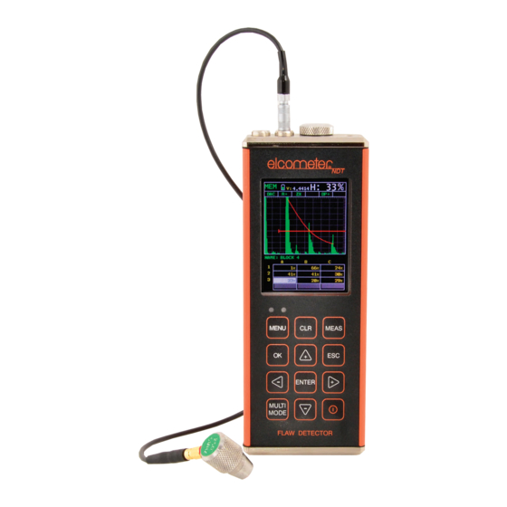
- Page 1 Model FD700DL+ & FD700+ Corrosion and Flaw Gauge Operating Instructions...
- Page 2 Elcometer NDT Ultrasonic Couplant Material Safety Data Sheet : www.elcometerndt.com/images/MSDS/elcometer_ultrasonic_couplant_hi_temp.pdf All other trademarks acknowledged. © Elcometer Limited 2012. All rights reserved. No part of this document may be reproduced, transmitted, transcribed, stored (in a retrieval system or otherwise) or translated into any language, in any form or by any means (electronic, mechanical, magnetic, optical, manual or otherwise) without the prior written permission of Elcometer Limited.
-
Page 3: Table Of Contents
Contents SECTION 1 : ABOUT YOUR GAUGE ........1 Introduction . -
Page 4: Section 1 : About Your Gauge
Thank you for purchasing this Elcometer NDT product. Welcome to Elcometer NDT. The FD700 series of Corrosion Gauge and Flaw Detector are world beating products. With the purchase of this gauge you now have access to the worldwide service and support network of Elcometer. - Page 5 Data can be downloaded to a computer for analysis and storage. To maximise the benefits of your new Elcometer NDT gauge, please take some time to read these Operating Instructions. Do not hesitate to contact Elcometer NDT or your Elcometer NDT supplier if you have any questions.
-
Page 6: The Keypad
2 THE KEYPAD Activates the primary menu structure containing menu tab groups. These tab groups then contain sub menu items, or functions. The sub menu items are organised in tab groups according to how closely they are related to the individual tab group names. -
Page 7: Getting Started
If you have not yet done so, refer to “Transducers For Thickness Measurement” on page 25, which will help you identify the correct transducer type. Alternatively contact Elcometer NDT, your local Elcometer NDT supplier or visit www.elcometerndt.com 3.3 FITTING THE TRANSDUCER... -
Page 8: Selecting Gauge Operating Mode (Thickness Gauge / Flaw Detector)
4 SELECTING GAUGE OPERATING MODE (THICKNESS GAUGE / FLAW DETECTOR) Your gauge combines a thickness gauge and a flaw detector in one unit. To select operating mode: 1. Press MENU/UTIL/GAUGE and press ENTER 2. Use UP and DOWN to select THICKNESS GAUGE, FLAW DETECTOR or REQUEST. 3. - Page 9 5.3 SELECTING MENU LANGUAGE The menus can be displayed in English, Spanish, and German. 1. Select MENU/SET/LANGUAGE. 2. Use LEFT and RIGHT to scroll the language options. 3. Once the desired language is displayed, press MEAS to return to the measurement screen. 5.4 ADJUSTING THE DISPLAY Your gauge has an AMOLED display which you can customise to your preferences: CHANGING THE DISPLAY BRIGHTNESS...
-
Page 10: Section 2 : Thickness Gauge
CHANGING THE RECT WAVEFORM TYPE The RECT waveform can be displayed FILLED or UNFILLED, as illustrated (screenshots taken with gauge set to FLAW mode). To adjust the RECT WAVE setting: 1. Select MENU/DISP/RECT WAVE. 2. Use LEFT and RIGHT to scroll to RECT WAVE. - Page 11 principal advantage of ultrasonic measurement over traditional methods is that ultrasonic measurements can be performed with access to only one side of the material being measured. Your gauge has four types of measurement screen: • A-Scan Waveform, RF • A-Scan Waveform, RECT •...
- Page 12 Units The current measurement units (Metric/English). Feature Status Bar Indicates the features currently enabled and in use: • Measurement Mode (P-E, PECT, PETP, E-E, E-EV, CT) • Differential Mode (ON/OFF) • High Speed Scan Mode (ON/OFF) • Alarm Mode (ON/OFF/AUDIBLE) •...
- Page 13 6.4 B-SCAN MEASUREMENT SCREEN The time-based B-Scan display provides a Hot Menu Enabled Hot Menu Disabled cross sectional view of the material being tested. In this example, the top, or accessible side of the material is represented as 0.00”, and the bottom, or blind surface at .500”. This mode is used when you need to inspect the profile of the blind surface.
- Page 14 B-Start and B-Depth are analogous to Delay and Range for a B-Scan display respectively. Delay and Range or B-Start and B-Depth may be adjusted in the hot menu or in the DISP section of the main menu. ADJUSTING DELAY AND RANGE (OR B-START AND B-DEPTH) The quickest way to adjust DELAY and RANGE is directly from the hot menu.
- Page 15 More information on thresholds can be found on the Elcometer NDT Knowledge Centre on www.elcometerndt.com.
-
Page 16: Measurement - Modes
7 MEASUREMENT - MODES Your gauge has two basic measurement modes, Pulse-Echo and Echo-Echo, plus a number of variations on these modes for specific measurement tasks. If an auto identified transducer is fitted to the gauge the appropriate mode will be automatically set. To select measurement mode manually, press MULTI MODE and then select the mode you want to use from the list displayed. -
Page 17: Setting Up The Thickness Gauge
8 SETTING UP THE THICKNESS GAUGE 8.1 AUTOMATIC TRANSDUCER IDENTIFICATION If using a coating thickness transducer, the gauge will ask you to confirm the transducer type. 1. Press OK to use the identified transducer. Note: Always select OK to use the identified transducer type. 2. - Page 18 For most applications the Off Block Zero will be sufficient, however if it is found the gauge linearity is off and extreme accuracy is required an On Block Zero should be conducted followed by an Off Block Zero. This will adjust and eliminate any error. These options may be accessed from MENU/PRB.
- Page 19 1. Press MULTI MODE, scroll to COATING ONLY (CT) and press ENTER. The measurement screen is displayed. 2. Apply a drop of couplant on the transducer and place the transducer in steady contact with the probe zero disk (battery cover) and obtain a steady reading - see illustration. Note: Disregard the value displayed;...
- Page 20 5. Press OK to select the material type and display the menu items with the new material type selected 6. Press MEAS to return to the measurement screen. KNOWN VELOCITY CALIBRATION If the material velocity is known, you can enter the velocity value directly into the gauge. A list of the sound velocities of common materials is given at the end of this instruction manual.
- Page 21 8.8 CALIBRATING - FOR A COATING Your gauge comes pre-set with a coating velocity of 2159 m s- that has been found to be a good approximation of coatings found in the field. Accuracy may be improved by calibrating for the coating in the same way that a material may be calibrated for, using either coating velocity or known coating thickness calibration.
-
Page 22: Measurement - Taking Readings
Note: If coating measurements are to be made with the coating applied to a metal surface, the calibration must be done in the same manner, with the samples coupled to a metal surface. However, if the coating is to be measured as a stand alone material, the calibration must be performed the same way. -
Page 23: Gates
10 GATES 10.1 INTRODUCTION Further information on gates may be found on the Elcometer NDT Knowledge Centre on www.elcometerndt.com 10.2 ADJUSTING THE GATES The quickest way to adjust the settings of the three gates is directly from the hot menu. Alternatively, adjust the values using the menus: 1. -
Page 24: Measurement - Options
ThruPaint capability is available in E-E and E-Ev modes, to activate through paint operation select one of these measurement modes using the "MULTI MODE" key. Further information may be found on the Elcometer NDT Knowledge Centre on www.elcometerndt.com 12 MEASUREMENT - OPTIONS 12.1 AUTO FIND... - Page 25 (above or below the x axis in the RF A-Scan) and the Rectified A-Scan display (whether the top or bottom half of the RF display is shown. For further information refer to the Elcometer NDT Knowledge Hub. To adjust POLARITY: Set the measurement screen view to RF.
-
Page 26: Transducers For Thickness Measurement
20dB, this value is added to the value of the gain setting. The option to adjust the Attenuator setting is found in MENU/TUNE/ATTENUATOR. 13 TRANSDUCERS FOR THICKNESS MEASUREMENT For further information on Transducers can be found on Elcometer NDT Knowledge Centre on www.elcometerndt.com. -
Page 27: Section 3 : Flaw Detector
SECTION 3 : FLAW DETECTOR 14 THE MEASUREMENT SCREEN When the GAUGE function is set to FLAW DETECTOR, the FD700 series becomes a flaw detector with the ability to detect the size and position of flaws and to differentiate between flaw types in various materials and welded joints. - Page 28 Height The signal amplitude height as a percentage of 100% full screen height. Feature Status Bar Indicates the features currently enabled and in use: • Toolkits (TRIG, AWS, TCG, DAC, DGS) • View (RF, R+, R-, FW) • Detect (ZX, FK, PK) •...
-
Page 29: Setting Up The Flaw Detector
14.3 +RECT MEASUREMENT SCREEN The +RECT view is similar to the RF display but shows only the positive half of the waveform. The detection point is indicated on the waveform. 14.4 -RECT MEASUREMENT SCREEN The -RECT view is the same as the +RECT view but shows only the negative half of the waveform. - Page 30 If the gauge is not set to the correct sound-velocity, all of the measurements the gauge makes will be erroneous by some fixed percentage. Note: The calibration procedures for the flaw detector and thickness gauge are different. The flaw detector does not use the same probe zero technique as the thickness gauge so for best thickness reading accuracy in flaw mode follow this guide carefully.
- Page 31 Note: This section describes performing a calibration using a straight beam contact transducer. Single and dual element probes may be calibrated in this way. Further information can be found on the Elcometer NDT website on www.elcometerndt.com. LOAD THE DEFAULT SETUP The gauge will require a few basic adjustments in order to get underway with the calibration process.
- Page 32 ENABLE AND CONFIGURE GATE 1 In order to measure, a gate is required. The width of the gate should be small enough, in terms of its width, in order to select specific reflections to measure. The purpose of the gate is to allow the gauge to detect on a particular signal.
- Page 33 The thickness reading should now match the known thickness. If the thickness is not correct, repeat the calibration procedure. 15.7 CALIBRATION FOR ANGLE BEAM TRANSDUCERS Further information on Calibration for Angle Beam Transducers can be found on the Elcometer NDT Knowledge Centre on www.elcometerndt.com.
-
Page 34: Measurement - Detecting Flaws
16 MEASUREMENT - DETECTING FLAWS Disclaimer: Inherent in ultrasonic measurement is the possibility that the instrument will use the second rather than the first echo from the back surface of the material being measured. This may result in a incorrect readings. Responsibility for proper use of the instrument and recognition of this phenomenon rests solely with the user of the instrument. - Page 35 17.2 DELAY & RANGE See “DELAY AND RANGE” on page 12. 17.3 ADJUSTING DELAY AND RANGE “Adjusting DELAY and RANGE (or B-START and B-DEPTH)” on page 13. 17.4 GAIN See Section “Gain” on page 13. 17.5 TO ADJUST THE GAIN VALUE “To Adjust the Gain Value”...
-
Page 36: Gates
18 GATES Your gauge is equipped with two gates which control the time measurement process and which play an important role in the detection and measurement of a flaw. Detections are only made within the boundaries of a gate. Anything outside of the start and range/width of the gate will be ignored. The height of a gate is also a threshold, and controls the level of sensitivity. -
Page 37: Trig - Trigonometry Mode
Setting Values Function THRESHOLD# Sets the sensitivity of the gate (its height). POLARITY POSITIVE Sets detection to occur on the positive going echo. NEGATIVE Sets detection to occur on the negative going echo. Some settings can be adjusted from the hot menu but all settings are found to adjust any of these settings: 1. - Page 38 TYPICAL TRIG MODE MEASUREMENT SCREEN When TRIG mode is enabled, the calculated measurements are displayed below the waveform display area at (B), and the signal amplitude as a percentage of full screen height at (A). CURVED SURFACE CORRECTION The gauge will also compensate for convex curved surfaces of longitudinally welded pipes.
-
Page 39: Aws - Weld Inspection
20 AWS - WELD INSPECTION 20.1 ABOUT AWS Further information on AWS - Weld Inspection can be found on the Elcometer NDT Knowledge Centre on www.elcometerndt.com. AWS D1.1 S : There are specific transducers that are required by the D1.1 standard. The TANDARD frequency specified by the standard is 2-2.5MHz. -
Page 40: Dac - Distance Amplitude Correction
A DAC curve is a gate with a variable threshold to compensate for a given reflector type and size measured at different depths. Further information found Elcometer Knowledge Centre www.elcometerndt.com. Note: Based on the gauge screen resolution, the dynamic range of the DAC is approximately 18 dB. - Page 41 DAC SETTINGS Setting Values Function Enables the DAC function. AUDIBLE Enables audible signal. Disables the DAC function. When disabled, all the other menu items are greyed out. DRAW Enables draw mode. Disables draw mode. MEAS Sets the quantity to be displayed when in the DAC function is %FSH enabled: %DAC...
- Page 42 21.3 DRAWING A DAC CURVE 1. Couple the transducer to the first calibration standard and peak up on the reflector, adjusting the gain to keep the signal height within the boundaries of the waveform display area, and at a suitable height to allow for attenuation at greater depths in the overall range to be tested.
-
Page 43: Tcg - Time Corrected Gain
The gain is adjusted at each selected point to display the signal amplitude at a predetermined reference level. Further information found Elcometer Knowledge Centre www.elcometerndt.com. 22.1 SETTING UP THE TCG FUNCTION Before setting up and using the TCG function you must: 1. - Page 44 22.2 DRAWING A TCG CURVE 1. Couple the transducer to the first calibration standard and peak up on the reflector to achieve maximum signal amplitude. 2. Enable the TCG function and adjust the TCG settings to your requirements (see “Adjusting TCG Settings” on page 42).
-
Page 45: Measurement - Options
23 MEASUREMENT - OPTIONS Further information found Elcometer Knowledge Centre www.elcometerndt.com. The Polarity function is used in the same way for the flaw detector as it is for the thickness gauge. Polarity is selectable depending on the VIEW, GT1, GT2 and DAC settings 23.1 DETECT MODE... - Page 46 The PRF setting will automatically be overridden according to the value of RANGE you have set. Long RANGE settings will slow down the PRF automatically. Note: Slower PRF settings use less electrical power, therefore if your current application does not need fast scanning speeds, selecting a slower PRF will help conserve battery life.
-
Page 47: Section 4 : Functions & Features Common To All Gauges
SECTION 4 : FUNCTIONS & FEATURES COMMON TO ALL GAUGES 24 MEASUREMENT - RECORDING YOUR READINGS Your gauge is equipped with a data logger -. With a data file open, all your measurements are saved into the file for later review and download to PC. 24.1 ABOUT THE DATA LOGGER With a data file open, as you take measurements, the measurement data is stored in files in the gauge memory. - Page 48 EMORY CAPACITY You can create and save as many data files as required up to the maximum capacity of the gauge memory (32 Mbit). If you try to create a new file which exceeds the memory capacity, the gauge will display an error message.
- Page 49 24.3 CREATING A NEW DATA LOGGER FILE - SEQUENTIAL FORMAT 1. To create a SEQ log data file: 2. Scroll to the DATA section of the main menu and highlight 3. Select NEW and use the (LEFT) and (RIGHT) keys to choose between grid and sequential log types 4.
- Page 50 5. To toggle the display between DIGITS view and B-SCAN view, press ESC. 6. If you are unable to take a measurement due to the measurement location being physically inaccessible, press CLR. The cell location in the data file is marked OBST (Obstruct). 7.
-
Page 51: Gauge Setups
25 GAUGE SETUPS Your gauge contains 64 configurable preset locations in which you can store custom gauge setups, each one optimised for a specific measuring application. These gauge setups can save time when conducting routine inspections of the same job or project. This feature also helps to eliminate error between two or more users during the setup and calibration process. - Page 52 1. Press MENU, SET and SAVE 2. Press ENTER to display the Save Setup edit box. 3. Scroll to NAME and then press ENTER to edit its value: • When you have finished, press OK to enter the value. 4. If you want to add a note, repeat step 3 for NOTE. 5.
-
Page 53: Data Transfer Software
26 DATA TRANSFER SOFTWARE Software is available which allows data to be transferred from your gauge to a PC. Presently Elcometer supplies NDT Link software for this purpose. To set-up other types of communications software: 1. Start the communications software. -
Page 54: Maintenance
The gauge does not contain any user-serviceable components. In the unlikely event of a fault, the gauge should be returned to your local Elcometer NDT supplier or directly to Elcometer NDT. The warranty will be invalidated if the instrument has been opened. -
Page 55: Technical Specification
29 TECHNICAL SPECIFICATION 29.1 PERFORMANCE Range Pulse-Echo P-E 0.63 mm to 3.048 m (0.025” to 100 ft) Pulse-Echo Coating PECT Material: 0.63 mm to 3.048 m (0.025” to 100 ft) Coating: 0.01 mm to 2.54 mm (0.001” to 0.100”) Pulse-Echo Temp Comp 0.63 mm to 3.048 m (0.025”... -
Page 56: Warranty
Additionally, Elcometer NDT warrants transducers and accessories against such defects for a period of 90 days from receipt by the end user. If Elcometer NDT receives notice of such defects during the warranty period, Elcometer NDT will either, at its option, repair or replace products that prove to be defective. -
Page 57: Condition And Preparation Of Surfaces
TF10M0B70M- 31.2 CALIBRATION BLOCKS Elcometer NDT offer a comprehensive range of calibration blocks to suit a wide range of applications and standards. Selecting the correct calibration block for the application is essential to ensure accurate evaluation. The form, shape and material of the calibration block should be appropriate for the material being inspected. -
Page 58: Sound Velocities Of Common Materials
34 SOUND VELOCITIES OF COMMON MATERIALS Sound velocity Sound velocity Material Material (m/s) (in/µs) (m/s) (in/µs) Aluminium 6350 0.250 Paraffin 2210 0.087 Bismuth 2184 0.086 Platinum 3962 0.156 Brass 4394 0.173 Plexiglas 2692 0.106 Cadmium 2769 0.109 Polystyrene 2337 0.092 Cast Iron 4572 0.180... -
Page 59: The Menu Commands - Thickness Gauge
35 THE MENU COMMANDS - THICKNESS GAUGE Menu (Thick.) Function Description ZERO PROBE Zeros your gauge in much the same way that a mechanical (PROBE) micrometer is zeroed. If your gauge is not zeroed correctly, all of the measurements made may be in error by some fixed value. - Page 60 Menu (Thick.) Function Description DISP VIEW Choose between RF wave, RECT (rectified) wave, BSCAN (DISPLAY) (cross section), and DIGITS (large digits) views. DELAY Adjust where the left side of the display window starts (B-START) according to thickness, in inches or millimetres. RANGE Set the overall depth of the viewable measurement area.
- Page 61 Menu (Thick.) Function Description TUNE MEASURE Choose which measurement mode to use. MODE POLARITY The gauge operates on a zero crossing detection principle. This feature toggles which stroke of the cycle the crossing detection uses, either positive or negative. PULSE Your gauge has adjustable pulse width (SPIKE, THIN, or WIDE) for both high penetration and resolution applications.
- Page 62 Menu (Thick.) Function Description GATE3 WIDTH Sets the overall width of the gate, in terms of distance, from (GATE 3) the starting value of HOLDOFF 3. HOLDOFF 3 Delay the starting point of Gate3 a specific distance from the first detection point found inside of the boundaries of the Gate2 settings.
- Page 63 Allows you to restore grids or sequential log files saved on a computer to your gauge via the RS232 port. ABOUT Provides Elcometer NDT contact information and your gauge software version. Refer to the help section of your gauge NDT Link software...
-
Page 64: The Menu Commands - Flaw Detector
36 THE MENU COMMANDS - FLAW DETECTOR Menu (Flaw Det.) Function Description TYPE Select the type of transducer being used (SINGLE or (Probe) DUAL). PULSE Your gauge has adjustable pulse width for both high penetration and resolution applications. The pulse width refers to the duration of time the pulser is on. - Page 65 Menu (Flaw Det.) Function Description DISP VIEW RF, +RECT, -RECT or RECTFW. (Display) DELAY Adjust where the left side of the display window starts according to thickness, in inches or millimetres. RANGE Set the overall depth of the viewable measurement area. It functions a lot like a zoom on a camera.
- Page 66 Menu (Flaw Det.) Function Description ALARM Toggles the alarm function of Gate1; ON, OFF or (Gate 1) AUDIBLE. The audible feature sounds a beeper when the waveform breaks the threshold level, either above or below, depending on the current DETECT setting. DETECT Set the alarm detection to occur either ABOVE or BELOW the gate THESHOLD value.
- Page 67 The list of trigger options will change according to which CURVE option has been selected. DPOLARITY Select the polarity of the DAC curves generated, either positive or negative. New function to be released soon. Please contact Elcometer NDT for more information.
- Page 68 DATA on a computer to your gauge via the RS232 port. ABOUT Provides Elcometer NDT contact information and your gauge software version. Refer to the help section of your gauge NDT Link soft- ware for a complete electronic manual covering data...
Need help?
Do you have a question about the FD700DL+ and is the answer not in the manual?
Questions and answers