Table of Contents
Advertisement
Advertisement
Table of Contents

Related Manuals for Topcon DL-501


Summary of Contents for Topcon DL-501
- Page 1 INSTRUCTION MANUAL DIGITAL LEVEL DL-501 21122 99024...
- Page 2 S Li-ion Li-ion This is the mark of the Japan Surveying Instruments Manufacturers Association.
- Page 3 • Verify that all equipment is included. "23. STANDARD EQUIPMENT" • DL-501 has a function to output data to a connected host computer. Command operations from a host computer can also be performed. For details, refer to "Communication Manual" and ask your local dealer.
- Page 4 <Screen title> etc.: Indicates screen titles. Notes regarding manual style • Except where stated, “DL" means DL-501 Advanced and DL-501 Standard in this manual. • Screens and illustrations appearing in this manual are of DL-501 Advanced. • Learn basic operations in "3. PRODUCT OUTLINE" and "4. BASIC OPERATION" before you read each measurement procedure.
-
Page 5: Table Of Contents
7. POWER ON/OFF ............. 24 Resolving Software Issues ..........25 8. FOCUSING AND SIGHTING THE STAFF ....26 Using the DL-501 Advanced ........... 26 Using the DL-501 Standard ..........28 9. CONNECTING TO EXTERNAL DEVICES ....29 Wireless Communication using Bluetooth Technology ... 29 Establishing a connection between the DL and paired Bluetooth device .............. - Page 6 CONTENTS 12.1 Route Setup ..............45 12.2 Height Difference Measurement ........49 12.3 Setting-Out Measurement ..........54 13. OTHER MEASUREMENT FUNCTIONS ....57 13.1 Measuring Horizontal Angle ..........57 13.2 Using the Instrument as a Standard Level ...... 57 14. CALCULATION FUNCTIONS ........58 14.1 Double-run Discrepancy ..........
- Page 7 21.3 Adjusting the Reticle ............. 109 22. POWER SUPPLY SYSTEM ........113 23. STANDARD EQUIPMENT ........114 23.1 DL-501 Advanced ............114 23.2 DL-501 Standard ............116 24. OPTIONAL ACCESSORIES ........117 25. SPECIFICATIONS ..........118 26. REGULATIONS ............122...
-
Page 9: Precautions For Safe Operation
1. PRECAUTIONS FOR SAFE OPERATION For the safe use of the product and prevention of injury to operators and other persons as well as prevention of property damage, items which should be observed are indicated by an exclamation point within a triangle used with WARNING and CAUTION statements in this operator’s manual. The definitions of the indications are listed below. - Page 10 1. PRECAUTIONS FOR SAFE OPERATION Staff Caution Do not use under thunderous weather conditions. The staff is conductive and if struck by lightning, death or injury could result. Handle with care when using near high voltage cables or transformers. The staff is ...
- Page 11 1. PRECAUTIONS FOR SAFE OPERATION Tripod Caution When mounting the instrument to the tripod, tighten the centering screw securely. Failure to tighten the screw properly could result in the instrument falling off the tripod, causing injury. Tighten securely the leg fixing screws of the tripod on which the instrument is mounted. ...
-
Page 12: Precautions
2. PRECAUTIONS Precautions concerning water and dust resistance DL conforms to IP54 specifications for waterproofing and dust resistance when the battery cover, External interface hatch, and Multi Port cap is closed. • Make sure that moisture or dust particles do not come in contact with the terminal or connectors. Operating the instrument with moisture or dust on the terminal or connectors may cause damage to the instrument. - Page 13 2. PRECAUTIONS • If the display is dirty, carefully wipe it with a soft, dry cloth. To clean other parts of the instrument or the carrying case, lightly moisten a soft cloth in a mild detergent solution. Wring out excess water until the cloth is slightly damp, then carefully wipe the surface of the unit.
-
Page 14: Product Outline
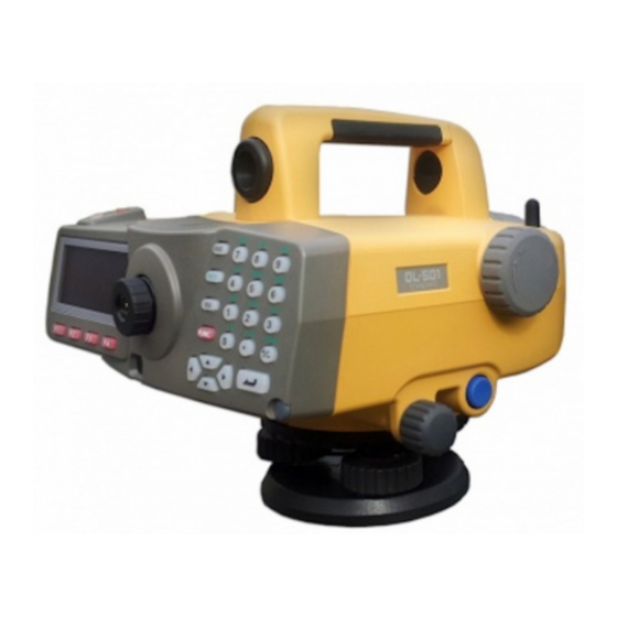
3. PRODUCT OUTLINE Parts of the Instrument Parts of the instrument (DL-501 Advanced) 1Handle 2Focusing knob 3Keyboard 4Measure key 5Leveling foot screw 6Base plate 7Horizontal circle positioning ring 8Horizontal circle Waterproof Multi Port 10Beam detector for Remote trigger 11Eyepiece screw... - Page 15 3. PRODUCT OUTLINE Parts of the instrument (DL-501 Standard) 1Simple finder • All other parts are identical to DL-501 Advanced. Functions of the instrument SD card slot The DL supports SD/SDHC cards (hereafter referred to collectively as "SD card" unless otherwise stated) for data write only.
-
Page 16: Mode Structure
3. PRODUCT OUTLINE Mode Structure The diagram below describes the different modes of the DL and key operations for navigating between them. J o b : J O B 1 R o u t e : e c . r e m a i n d e r D L - 5 0 1 A d v M e a s . -
Page 17: Bluetooth Wireless Technology
Contact your local dealer in advance. "26. REGULATIONS" • TOPCON CORPORATION is not liable for the content of any transmission nor any content related thereto. When communicating important data, run tests beforehand to ascertain that communication is operating normally. - Page 18 3. PRODUCT OUTLINE However, even if the DL is used within proximity to the above equipment with no adverse effects with regard to Bluetooth communication, moving a Bluetooth compatible device (including the DL) closer to said equipment may result in electronic noise in sound or images, adversely affecting the performance of televisions and radios.
-
Page 19: Basic Operation
Measurement (Auto Focus) Automatically focuses on the staff and starts measurement. (DL- 501 Advanced) Measure key Starts measurement (DL-501 Standard) Softkey operation Softkeys are displayed on the bottom line of the screen. {F1} to {F4} Select the function matching the softkeys... - Page 20 4. BASIC OPERATION {BS} Delete a character on the left. {} Select/accept input word/value. Selecting options Move the cursor/selection item up/down {}/{} Move the cursor/selection item left/right or select other option {} Select/accept the option Other operation ...
- Page 21 4. BASIC OPERATION Key operation for Remote trigger (DLC1A) DLC1A comes as standard with the DL-501 Advanced and is an optional accessory for the DL-501 Standard. "4.1 Basic Key Operation" Beam source Key panel {MEAS} {ENT} {ESC} The DL is operated from the Remote trigger by pointing the Remote trigger beam at the DL and pressing the required operation keys.
- Page 22 4. BASIC OPERATION • If other DLC1A-compatible instruments are turned ON and placed within the operating range of the Remote trigger, they may be unintentionally operated at the same time. • Do not place the Remote trigger under heavy objects or in a tight space. A key may be continuously depressed and deplete battery power.
-
Page 23: Display Functions
4. BASIC OPERATION Display Functions Status screen D L - 5 0 1 A d v S / N 9 9 9 9 9 9 A p p l i : V e r . X X X X - X X - X X S e n s o r : V e r . - Page 24 4. BASIC OPERATION "Battery low! Please charge battery." (with audio tone) displayed alternately with current screen : No power remains. Stop measurement and save data. Then turn the instrument off and charge the battery. "5.1 Battery Charging" *5 Bluetooth communication status Connection established (flashing): Waiting...
-
Page 25: Using The Battery
5. USING THE BATTERY Types of power source: "22. POWER SUPPLY SYSTEM" Battery Charging The battery was not charged at the factory. Charge the battery fully before using the DL. • The charger will become rather hot during use. This is normal. •... -
Page 26: Installing/Removing The Battery
5. USING THE BATTERY • Slots 1 and 2: The charger starts charging the battery mounted first. If you place two batteries in the charger, the battery in slot 1 is charged first, and then the battery in slot 2. ( step 2) •... - Page 27 5. USING THE BATTERY PROCEDURE Mounting the battery 1. Push the catch on the battery cover away from Catch the objective lens. Battery cover 2. Insert the battery in the direction of the arrow on the side of the battery. 3.
- Page 28 5. USING THE BATTERY PROCEDURE Using the Battery adapter Insert the BDC46C into the battery adapter (SB178). The battery can now be mounted in the same way as the BDC58/70. 1. Align the notch in the BDC46C with the SB178 as shown at right.
-
Page 29: Setting Up The Instrument
6. SETTING UP THE INSTRUMENT • Mount the battery in the instrument before performing this operation because the instrument will tilt slightly if the battery is mounted after leveling. Setting Up PROCEDURE 1. Make sure the legs are spaced at equal intervals and the head is approximately level. - Page 30 6. SETTING UP THE INSTRUMENT PROCEDURE Leveling with the Spherical head tripod 1. Loosen the centering screw. 2. Slide the instrument across the tripod head until the bubble is centered in the circular level. 3. Tighten the centering screw. 4. Level the DL using the leveling foot screws. Spherical head tripod Centering...
- Page 31 6. SETTING UP THE INSTRUMENT PROCEDURE Leveling on the screen Turn the instrument on. "7. POWER ON/OFF" 2. The screen shown at right is displayed. ME NU 3. Center “” in the circular level. "6.2 Leveling PROCEDURE Leveling with the Spherical head tripod/"6.2 Leveling PROCEDURE Leveling with the Flat head tripod"...
-
Page 32: Power On/Off
Set to "No" to skip levelling on startup. • Do not remove the battery while the TOPCON logo is displayed. • "Tilt warn." in "Obs. condition" should be set to "No" if the display is unsteady due to vibration or strong wind. -
Page 33: Resolving Software Issues
• Be sure to back up stored data to an external memory device or computer in advance. PROCEDURE Initializing data 1. Power OFF the instrument. 2. Press { } while holding {BS}, {F1}, and {F3} until the TOPCON logo appears. "Clearing memory..." is displayed and data is initialized. The instrument then powers on as normal. -
Page 34: Focusing And Sighting The Staff
8. FOCUSING SIGHTING STAFF Using the DL-501 Advanced •If the view finder sighting axis is not aligned with the sighting axis of the objective lens, errors will occur when taking measurements. Always make sure the axes are correctly aligned when using the view finder. - Page 35 8. FOCUSING AND SIGHTING THE STAFF 5. Turn the horizontal fine motion knobs until that vertical line is centered in the field of view. 6. Looking through the view finder, turn the view finder eyepiece screw until the 2 circles are focussed.
-
Page 36: Using The Dl-501 Standard
If the staff and reticle deviate, return to step 2. "8.1 Using the DL-501 Advanced Eliminating parallax" •Repeat steps 3 and 4 each time measurement is performed. -
Page 37: Connecting To External Devices
9. CONNECTING TO EXTERNAL DEVICES The DL can be connected to a data collector to allow remote operation. Read this manual in conjunction with the operator’s manual for the relevant external device and software thereof. Wireless Communication using Bluetooth Technology The Bluetooth module incorporated in the DL can be used for communication with Bluetooth devices such as data collectors. - Page 38 9. CONNECTING TO EXTERNAL DEVICES 5. When "Authenticate" is set to "Yes", input the M o d e B l u e t o o t h same passkey as that for the intended A u t h e n t i c a t e : Y e s companion device.
-
Page 39: Establishing A Connection Between The Dl And Paired Bluetooth Device
9. CONNECTING TO EXTERNAL DEVICES Bluetooth Device Address This is a number unique to one particular Bluetooth device used to identify devices during communication. This number consists of 12 characters (numbers 0 to 9 and letters from A to F). Some devices may be referred to by their Bluetooth device address. -
Page 40: Outputting Data Using Bluetooth Communication
9. CONNECTING TO EXTERNAL DEVICES Communication between the DL and Companion Device Setting a data collector as the companion device allows measurement and other operations to be performed from the data collector side. • Bluetooth communication causes DL battery power to be depleted at a rate higher than that for normal operation. -
Page 41: Connecting Via Communication Cable
9. CONNECTING TO EXTERNAL DEVICES 3. Select "Comms output" in <JOB menu> and set "Com.locat." "18.1 Outputting JOB Data PROCEDURE Outputting JOB data to host computer" DL starts outputting data. J o b i d J O B 1 F o r m a t C S V _ 1 O u t p u t t i n g... -
Page 42: Basic Operation
10.BASIC OPERATION 10.1 Reading the Staff Simply focus on the RAB* code for an automatic reading of the staff. The following explains how to read the RAB code of the staff. *RAB code (RAndom Bi-directional code) is a coded staff used with certain digital levels. ... - Page 43 10. BASIC OPERATION intermediate site, new site) ° T0: Reference temperature of 20 C α : Line expansion coefficient Δ h: Height difference PROCEDURE Setting up the staff 1. Set the foot plate on the ground so that the staff will not sink. 2.
-
Page 44: Measuring In Measure Mode
Press [STOP] or the Measure key to stop reading. Press {ESC} to cancel the reading. •Auto focus functionality is not available for the DL-501 Standard. Therefore [FOCUS] is not displayed in the screen of step 2. -
Page 45: Simple Measurement
11.SIMPLE MEASUREMENT This chapter explains how to measure height difference or elevation without setting a route. •The maximum number of points per JOB is 2000. 11.1 Measuring Height Difference This function allows the user to calculate the height difference ( ) between backsight (A) and foresight (B). - Page 46 11. SIMPLE MEASUREMENT • [PT.ID]: Press to change the current point ID. P t . i d Subsequent point IDs will be assigned 0 0 0 0 A automatically in either ascending or M e a s . p t t y p e : B S descending order.
- Page 47 11. SIMPLE MEASUREMENT 8. Check point ID, double-run setting, and measurement results. F S 0 0 0 1 Press [OK]. 2 . 3 4 5 6 7 m Results are recorded and the screen in step 7 1 2 . 3 4 5 is restored.
-
Page 48: Measuring Elevation
11. SIMPLE MEASUREMENT 11.2 Measuring Elevation This function allows the user to calculate the elevation (HA + ) of a specified point (B) based on the elevation of known point (A). HA (Elevation HA + dH of known point) 1. Select "Meas" in <Menu>. 2. - Page 49 11. SIMPLE MEASUREMENT 7. Check point ID, double-run setting, and measurement results. B S 0 0 0 1 Press [OK]. 2 . 4 5 6 7 8 m 1 7 . 8 9 1 8. Measure foresight. F S 0 0 0 1 T I L T C N F G PT.ID...
-
Page 50: Viewing Simple Measurement Data
11. SIMPLE MEASUREMENT • When operation has been canceled after moving screens during measurement, the following O p e r a t i o n w i l l c o n t i n u e message will be displayed the next time f r o m l a s t m e a s u r e m e n t . -
Page 51: Deleting Simple Measurement Data
11. SIMPLE MEASUREMENT • Press [SRCH] to search for point data by S e a r c h point id. P t . i d I S 0 0 0 3 5. Press {ESC} to return to <Simple meas. data menu>... - Page 52 11. SIMPLE MEASUREMENT • Press [DETAIL] in the second page to B S 0 0 0 0 display detailed information for the 0 0 0 1 selected simple meas. data. 0 0 0 2 I S 0 0 0 3 D E L •...
-
Page 53: Height Difference Measurement
12.HEIGHT DIFFERENCE MEASUREMENT Height difference measurement allows the user to calculate the relative height between a known point and a specified point. The instrument is moved from instrument station to instrument station along a route from the known point to the unknown point taking measurements at each section. The total of measurements at all sections gives the height difference between the known point and the specified point. - Page 54 12. HEIGHT DIFFERENCE MEASUREMENT 2. Select "Height dif." in <Meas menu>. M e a s m e n u H e i g h t d i f . 2 . C h e c k & a d j u s t . 3 .
- Page 55 12. HEIGHT DIFFERENCE MEASUREMENT 4. Press [NEW]. R o u t e s e t t i n g : R 1 DETAIL L I S T N E W 5. Set the following data items. R o u t e i d (1) Route ID R o u t e - 0 0 1 (2) Memo...
- Page 56 12. HEIGHT DIFFERENCE MEASUREMENT B F d i s t d i f f . 1 . 0 0 0 T o t a l d i s t d i f f . : 3 . 0 0 0 6.
-
Page 57: Height Difference Measurement
12. HEIGHT DIFFERENCE MEASUREMENT PROCEDURE Editing route ID 1. Select "Route" in <Height dif. menu>. 2. Press [LIST]. Align the cursor with the desired R o u t e s e t t i n g route and press {}. : R 1 DETAIL L I S T... - Page 58 12. HEIGHT DIFFERENCE MEASUREMENT PROCEDURE Measurement procedure BFFB 1. Select "Meas" in <Menu>. 2. Select "Height dif." in <Meas menu>. 3. Select "Measurement" in <Height dif. menu>. H e i g h t d i f . m e n u R o u t e M e a s u r e m e n t 4.
- Page 59 12. HEIGHT DIFFERENCE MEASUREMENT 9. Measure backsight. F F B 0 0 0 0 • [FOCUS]: Press to perform Auto Focus only. B S 1 F S 1 T I L T C N F G PT.ID F O C U S •...
- Page 60 12. HEIGHT DIFFERENCE MEASUREMENT 12. Check point ID, double-run setting, and measurement results. R o u t e 0 1 - A 1 - 0 0 0 1 Press [OK]. 1 . 2 3 4 5 m 3 4 . 4 5 6 13.
- Page 61 12. HEIGHT DIFFERENCE MEASUREMENT • Press [OK] in the screen shown at right to record results and return to the previous R o u t e 0 1 - A 1 - 0 0 0 2 screen. 1 . 3 4 5 6 m Measurements of subsequent IS points can 3 0 .
-
Page 62: Setting-Out Measurement
• The pre-measurement of step 8 will be performed in rapid single mode regardless of the "Meas mode" setting in "Obs.condition". • Auto focus functionality is not available for the DL-501 Standard. Therefore [FOCUS] is not displayed in the screen of steps 8, 9 and 11. - Page 63 12. HEIGHT DIFFERENCE MEASUREMENT 3. Press [MODE] to switch input mode between S - O d a t a elevation, height difference, and distance. 0 . 0 0 0 0 0 M O D E R E A D 4. Input the desired elevation/height difference/ S - O d a t a distance and press [OK].
- Page 64 12. HEIGHT DIFFERENCE MEASUREMENT 1. Press [READ] in the screen at right. ( S - O d a t a screen at right is that for elevation mode) 4 1 . 0 0 0 0 0 M O D E R E A D 2.
-
Page 65: Other Measurement Functions
13.OTHER MEASUREMENT FUNCTIONS 13.1 Measuring Horizontal Angle You can measure the horizontal angle between point A and point B by using the horizontal circle. Horizontal angle 13.2 Using the Instrument as a Standard Level By using the numeric scale side of the staff, you can use the DL as a standard level. Simply focus on the staff using the eyepiece and read the scale. -
Page 66: Calculation Functions
14.CALCULATION FUNCTIONS The functions described in this chapter allow the user to calculate double-run discrepancy, or closure error for closed leveling links/loops using data from measured routes. • Route data used in calculation must all come from the same JOB. 14.1 Double-run Discrepancy This function compares the height difference results recorded for the go and return runs on a specified... - Page 67 14. CALCULATION FUNCTIONS Align the cursor with the route you wish to use * R 0 0 1 as the go run and press { }. <Route R 0 0 2 selection> is restored. • Press [TOP] to move to the first route on the first page.
-
Page 68: Closure Error
14. CALCULATION FUNCTIONS 14.2 Closure Error This function calculates the closure error for closed leveling links and closed leveling loops. A leveling link ties two different bench marks (with known elevation) together by combining multiple consecutive routes. The start points and end points of a link are different. A leveling loop, on the other hand, closes on the same bench mark at which it started. - Page 69 14. CALCULATION FUNCTIONS • When calculating closure for a leveling link/ R o u t e 0 0 1 loop comprising multiple connected routes, R o u t e s e t t i n g set the measurement direction. This direction : R 0 0 1 is set by specifying the start point for each S t a r t p t...
- Page 70 14. CALCULATION FUNCTIONS 5. Repeat steps 3 to 4 and add all other routes 0 0 1 R 0 0 1 used in the link/loop. 0 0 2 R 0 0 2 0 0 3 R 0 0 3 Press [OK] when all routes have been added. 0 0 4 L A S T T O P...
-
Page 71: Adjusting For Closure
14. CALCULATION FUNCTIONS 14.3 Adjusting for Closure This function provides two methods for distributing closure error among points on route. 1. Press [ADJUST] in the results screen for D b l e - r u n d i s c r e p a n c y double-run discrepancy or closure error. - Page 72 14. CALCULATION FUNCTIONS Example: Total misclosure: 6mm : Fixed point : Measurement point : Start/End point "Weighted": 100 100 Section length "Linear": "Fixed pt" 0.75 0.75 0.75 0.75 0.75 0.75 0.75 0.75 "Meas pt" •If "Meas pt rec" is set to "Yes", "Fixed pt rec" is also set to "Yes" automatically. Press [OK] to display elevation settings.
- Page 73 14. CALCULATION FUNCTIONS Double-run Discrepancy ("Fixed pt rec" = "Yes") Press [NEXT]/[PREV] to display results for the next/previous measurement point. F i x e d p t N o . 0 0 0 1 P t . i d F S 0 0 0 1 ...
- Page 74 14. CALCULATION FUNCTIONS Link Closure/Loop Closure Route 1 ("Fixed pt rec" = "Yes") R o u t e 0 0 1 Press [NEXT]/[PREV] to display results for the next/previous measurement point. P t . i d R T 0 0 1 B S 0 0 0 0 A d j .
- Page 75 14. CALCULATION FUNCTIONS • Pressing [LIST] automatically displays the point list when only one route exists. Align the cursor with a point id and press B S 0 0 0 0 {} to display adjustment results for that F S 0 0 0 1 point.
- Page 76 14. CALCULATION FUNCTIONS Press {} to return to the screen in step 3. A d j u s t e d d a t a R o u t e - 0 0 1 - > R o u t e - 0 0 1 _ 0 1 R e c o r d i n g 3 / 3 •...
-
Page 77: Reobserved Route Merge
14. CALCULATION FUNCTIONS 14.4 Reobserved Route Merge This function merges an existing route (the base route) with a reobserved section of that same route (the reobserved route). Reobs. end pt Reobs. start pt Base route Reobserved route Merged route As shown above, the merged route uses the reobs. start point id from the base route and the reobs. end point id from the reobserved route. - Page 78 14. CALCULATION FUNCTIONS 3. Select "Reobs.route setting" in <Route R o u t e m e n u menu>. R e o b s . r o u t e s e t t i n g 4. Align the cursor with "Base route id" and press R e o b s .
- Page 79 14. CALCULATION FUNCTIONS 5. Align the cursor with "Reobs.end pt" and press R e o b s . e n d p t [LIST]. Align the cursor with the point you wish R o u t e - 0 1 - E D 0 0 0 8 to set as the end point and press {}.
-
Page 80: Selecting/Deleting A Job
15.SELECTING/DELETING A JOB 15.1 Selecting a JOB • A total of 20 JOBs have been prepared, and JOB1 was selected when your DL was shipped from the factory. • The names of the JOBs have been preset as JOB1 to JOB20; you can change them to any names you wish. -
Page 81: Deleting A Job
15. SELECTING/DELETING A JOB 15.2 Deleting a JOB It is possible to clear the data within a designated JOB. After the data has been cleared, the JOB name returns to the name allocated when the DL was shipped. • A JOB (containing a route) that has not been output to an external device cannot be deleted. PROCEDURE 1. -
Page 82: Backing Up A Job
15. SELECTING/DELETING A JOB 15.3 Backing Up a JOB It is possible to back up JOB data to a host computer or external memory device. PROCEDURE 1. Select “Management” in <Menu>. 2. Select “JOB" in <Management menu>. <JOB menu> is displayed. 3. -
Page 83: Restoring A Job
15. SELECTING/DELETING A JOB 15.4 Restoring a JOB It is possible to restore backed up JOB data from an external memory device to the internal memory. PROCEDURE 1. Select “Management” in <Menu>. 2. Select “JOB" in <Management menu>. <JOB menu> is displayed. 3. -
Page 84: Deleting Backed Up Data
15. SELECTING/DELETING A JOB 6. Align the cursor with "JOB id when restored" L o c a t i o n : S D and press [LIST]. The JOB list screen is J O B i d i n e x t . m e m o r y displayed. - Page 85 15. SELECTING/DELETING A JOB 4. Select "SD" or "USB" in "Location". B a c k u p J O B d e l e t i o n D e s t i n a t i o n : Press [OK] to display the JOB list.
-
Page 86: Route Settings
16.ROUTE SETTINGS 16.1 Deleting a Route It is possible to delete a route or routes within the current JOB. • A route that has not been output to an external device (displayed with *) cannot be deleted. PROCEDURE 1. Select “Management” in <Menu>. M e n u M e a s M a n a g e m e n t... -
Page 87: Displaying Route Information
16. ROUTE SETTINGS 6. Press [YES]. The route is deleted and the R o u t e d e l e t i o n route list is restored. R o u t e s e t t i n g d e l e t i o n C o n f i r m ? Y E S... -
Page 88: Deleting Is Points
16. ROUTE SETTINGS 5. Align the cursor with the desired start info./IS S t a r t i n f o . 2 point (only when IS results recorded)/fixed pt./ R o u t e 0 1 - A 1 - 0 0 1 1 measurement point and press {}. - Page 89 16. ROUTE SETTINGS • Press [DETAIL] on page 2 to display R T 0 1 _ I S 0 0 0 0 6 D E L detailed information for the selected IS R T 0 1 _ I S 0 0 0 0 7 D E L point.
-
Page 90: Managing Known Point Data
17.MANAGING KNOWN POINT DATA In this menu it is possible to register, view, or delete known point data. • Known point data is recorded in the current JOB. However, data recorded using the misclosure adjustment function is managed in the relevant route. •... -
Page 91: Reading In From External Media
Output format and command operations: “Communication Manual" • DL-501 does not check for duplicate file names when reading in data from external media. Read in data with the same file name as existing data will be registered separately. PROCEDURE Reading in from an SD card 1. - Page 92 17. MANAGING KNOWN POINT DATA 4. Select “Comms input”. K n o w n p o i n t d a t a m e n u 1 . K e y i n c o o r d C o m m s i n p u t 3 .
-
Page 93: Viewing Known Point Data
17. MANAGING KNOWN POINT DATA 4. Select “Comms input”. 5. Set "Location" to "USB". C o m m s i n p u t L o c a t i o n U S B 6. Align the cursor with the file to be read in and press {}. - Page 94 17. MANAGING KNOWN POINT DATA 4. Select “JOB data”. K n o w n p o i n t s e l e c t i o n J O B d a t a 2 . R o u t e d a t a 5.
-
Page 95: Deleting Known Point Data
17. MANAGING KNOWN POINT DATA 5. Align the cursor with the relevant route and A list of known point data in press {}. that route is displayed. L I N E 0 1 L I N E 0 2 L I N E 0 3 ...P T O P L A S T... - Page 96 17. MANAGING KNOWN POINT DATA • Press [DETAIL] in the second page to P M - B M - 0 0 1 display detailed information for the P M - B M - 0 0 2 selected known point data. P M - F I X - 0 0 3 P M - F I X - 0 0 4 D E L...
-
Page 97: Outputting Data
18.OUTPUTTING DATA It is possible to output JOB and route data to a host computer or external memory device. Bluetooth communication: "9.4 Outputting data using Bluetooth communication" Communication cables: "24. OPTIONAL ACCESSORIES" Output format and command operations: “Communication Manual" •... - Page 98 18. OUTPUTTING DATA 8. Align the cursor with the JOB to be output and J O B 1 press {}. J O B 2 J O B 3 • The numbers to the right represent the J O B 4 number of data items in each JOB.
- Page 99 18. OUTPUTTING DATA 10. Output starts. • Do not remove the SD card or turn off the DL while files are being copied/transferred. 11. Press {ESC} to return when "Completion" is displayed. •SD cards up to 4GB supported. SDHC supported. PROCEDURE Outputting JOB data to a USB memory device 1.
-
Page 100: Outputting Route Data
18. OUTPUTTING DATA • Do not disconnect the USB memory or turn off the DL while files are being copied/ transferred. 11. Press {ESC} to return when "Completion" is displayed. • Start cond. input in steps 4 to 5 is optional when restarting measurement of a partially-completed route. - Page 101 18. OUTPUTTING DATA 7. Select the route ID to be output and press O U T {}. O U T "OUT" appears to the right of the route ID R O U T E 1 1 selected. You can select as many route IDs as * R O U T E A 2 2 you want.
- Page 102 18. OUTPUTTING DATA 10. Enter a filename and press [OK]. 11. Output starts. • Do not remove the SD card or turn off the DL while files are being copied/transferred. 12. Press {ESC} to return when "Completion" is displayed. PROCEDURE Outputting route data to a USB memory device 1.
-
Page 103: Changing The Settings
No*, K=0.142, K=0.20 Auto Focus setting. (A.F.setting): Yes*, No Tilt warning (Tilt warn): Yes*, No • "Rec cond." cannot be changed for a JOB already containing route data. • There is no "A.F. setting" for the DL-501 Standard. -
Page 104: Instrument Configuration
19. CHANGING THE SETTINGS SD mirroring This function synchronizes the content of the SD card with the internal memory. Data stored to the internal memory will automatically be stored to the SD card. Data deleted from the internal memory will also be deleted from the SD card. 19.2 Instrument Configuration P o w e r o f f... -
Page 105: Units
19. CHANGING THE SETTINGS STX/ETX (CSV) This setting is relevant only when "Com.locat." is set to "Com". When this setting is set to "Yes", a "start of text" (STX) code is added to the start, and an "end of text" (ETX) code to the end of output text data. When "Com.locat."... -
Page 106: Restoring Default Settings
PROCEDURE Performing a reset 1. Turn the instrument off. 2. Press { } while holding {BS}, and {F4} until the TOPCON logo appears. "Default set" is displayed and the instrument is reset. 3. Power the instrument on as normal. -
Page 107: Warning And Error Messages
20.WARNING AND ERROR MESSAGES The following is a list of the error messages displayed by the DL and the meaning of each message. If the same error message is repeated or if any message not shown below appears, the instrument has malfunctioned. - Page 108 20. WARNING AND ERROR MESSAGES File read error! An error occurred while trying to read in a file. Contact your local dealer. File system error! File write error! It is impossible to read in/write data. When trying to write to a USB device, check that the USB is not read-only. Otherwise, contact your local dealer.
- Page 109 20. WARNING AND ERROR MESSAGES Light is entering the eyepiece. Use your hand or body to shield the eyepiece from the light source. Meas.pt record full! No more meas. points can be recorded. Delete unnecessary JOB or route data and try again. Meas.
- Page 110 20. WARNING AND ERROR MESSAGES No route setting Route settings have not been made. No SD card inserted. No SD card inserted in the SD card slot. Check that the SD card is inserted correctly. SD card slot No staff No staff detected by the Auto Focus function.
- Page 111 20. WARNING AND ERROR MESSAGES SD card is write protected. SD card is write protected. Data cannot be written to the SD card. Cancel write protection or use a different SD card. SD card record is stopped. Continue? Data cannot be written to the SD card despite "SD mirroring" being set to "On", perhaps because the SD card is not inserted correctly.
- Page 112 20. WARNING AND ERROR MESSAGES The following cannot be used in a file id. A file name containing "*", "?", or "/" is invalid. Create a file name which does not use any of these characters. Time out The Auto Focus function could not read the staff, or Auto Focus could not complete within the time specified.
-
Page 113: Checks And Adjustments
21.CHECKS AND ADJUSTMENTS DL is a precision instrument that requires fine adjustments. It must be inspected and adjusted before use so that it always performs accurate measurements. • Always perform checking and adjustment in the proper sequence beginning from "21.1 Circular Level"... -
Page 114: Tilt Sensor
21. CHECKS AND ADJUSTMENTS 21.2 Tilt Sensor If the tilt angle shifts from tilt angle 0° (zero point), the instrument is not correctly levelled. The actual circular level and graphic level will not be displayed correctly. Perform the following procedure to cancel the tilt zero point error. PROCEDURE Checking and adjusting 1. - Page 115 21. CHECKS AND ADJUSTMENTS 7. Wait a few seconds for the screen to stabilize, T i l t a d j u s t m e n t then read the automatically compensated F2 0 ’ 2 5 " angles (X2 and Y2). - 1 ’...
- Page 116 21. CHECKS AND ADJUSTMENTS When both offset values fall within the range ±1’, adjustment is complete. Press {ESC} to return to <Config menu>. If one of the offset values (Xoffset, Yoffset) exceeds ±1’, repeat the check and adjustment procedures from the beginning. If the difference continues to exceed ±1’...
-
Page 117: Adjusting The Reticle
21. CHECKS AND ADJUSTMENTS 21.3 Adjusting the Reticle The reticle cross-lines can be corrected if out of adjustment. While reading the staff RAB-code, adjust the reticle by correcting the reference value of the CCD line sensor and then make mechanical adjustments to the instrument. - Page 118 21. CHECKS AND ADJUSTMENTS 7. Measure staff b. 1 . 3 4 5 6 0 m 1 5 . 0 8 0 8. Press [OK] to accept the results. 9. Measure staff b. A a b 1 . 3 4 5 6 0 m 1 5 .
- Page 119 21. CHECKS AND ADJUSTMENTS 17. When adjustment is necessary, press [YES]. • Press [NO] if no adjustment is necessary. 18. Press [YES] in the confirmation dialog shown at right. A d j u s t ? • Press [NO] to cancel and return to <Meas menu>.
- Page 120 When powered off during measurement of point B: point B/staff a measurement screen When powered off while displaying difference results: difference results screen • Auto focus functionality is not available for the DL-501 Standard. Therefore [FOCUS] is not displayed in the screen of steps 4 and 14.
-
Page 121: Power Supply System
22.POWER SUPPLY SYSTEM Operate your DL with the following combinations of power equipment. • Never use any combination other than those indicated below. If you do, the DL could be damaged. Those indicated by * are standard accessories. Others are optional accessories (sold separately). Charger Power cable Battery... -
Page 122: Standard Equipment
23.1 DL-501 Advanced DL main unit ............. 1 Battery (BDC58/70). - Page 123 23. STANDARD EQUIPMENT Remote Trigger (DLC1A) Changing battery cells • Remove the battery cell when the remote trigger is not to be used for a long time. PROCEDURE 1. Pull the catch on the battery cover down. Remove the battery cover.
-
Page 124: Standard
23.2 DL-501 Standard DL main unit ............. 1 Battery (BDC58/70). -
Page 125: Optional Accessories
24.OPTIONAL ACCESSORIES The following are optional accessories which are sold separately from the DL. Remote Trigger (DLC1A) Optional accessory for the DL-501 Standard. Diagonal eyepiece (DE28/DE29) The diagonal eyepiece is convenient for observations in narrow spaces. Magnification: DE28:... -
Page 126: Specifications
25.SPECIFICATIONS Except where stated, the following specifications apply to both DL-501 Advanced and DL-501 Standard. Telescope Length: 280mm Aperture: 45mm (1.8 inch) Magnification: Image: Erect Resolving power: 3" Field of view: 1°20' (2.3m/100m) Minimum focus: 1.5m (5.0 ft) Stadia ratio:... - Page 127 Distance 0.001/0.01/0.1m (0.01/0.1/1ft) (selectable) Accuracy : (ISO17123-2 compatible) Height (Standard deviation for 1 km of double-run leveling) Electronic measurement 0.2mm (with BIS30A, DL-501 Advanced only) 0.3mm (with BIS20/30) 1.0mm (with BGS40/50) Visual measurement 1.0mm (with BGS40/50) Distance (Electronic measurement) ±10mm or less (10m or less) ±(0.1% x D) or less (over 10 to less than 50m)
- Page 128 Authentication: Yes/No (selectable) Power Supply Power source: Rechargeable Li-ion battery BDC58/70 Working duration at 20 °C (using BDC58/70): DL-501 Advanced Manual focus and measurement: about 12 hours Automatic focus and measurement: about 9 hours DL-501 Standard about 14 hours...
- Page 129 Size: 58 (W) X 28 (D) X 5090 (H) mm Weight: 3.0kg (1 staff only), 3.6kg (w/ case) Remote trigger (DLC1A) (optional accessory for the DL-501 Standard) Interface: Modulated infrared LED Power source: Coin-type battery x 1 (CR2032) (3V DC) Operating range: within 0.5m (operating range may vary with different operating...
-
Page 130: Regulations
26.REGULATIONS Region/ Directives/ Labels/Declarations Country Regulations U.S.A. FCC-Class A FCC Compliance WARNING: Changes or modifications to this unit not expressly approved by the party responsible for compliance could void the user's authority to operate the equipment. NOTE: This equipment has been tested and found to comply with the limits for a Class A digital device pursuant to Part 15 of the FCC Rules. - Page 131 26. REGULATIONS Region/ Directives/ Labels/Declarations Country Regulations California Recycling and NY, Batteries U.S.A. Canada ICES-Class A This Class A digital apparatus meets all requirements of Canadian Interference-Causing Equipment Regulations. Cet appareil numérique de la Class A respecte toutes les exigences du Réglement sur le matériel brouilleur du Canada.
- Page 132 Under such conditions, please test the instrument performance before use. This product complies with the electromagnetic environmental testing of industrial locations. Model: DIGITAL LEVEL DL-501 Manufacturer Name: TOPCON CORPORATION Address: 75-1, Hasunuma-cho, Itabashi-ku, Tokyo, 174-8580...
- Page 134 Please see the attached address list or the following website for contact addresses. GLOBAL GATEWAY http://global.topcon.com/ ©2012 TOPCON CORPORATION ALL RIGHTS RESERVED...
Need help?
Do you have a question about the DL-501 and is the answer not in the manual?
Questions and answers