Table of Contents
Advertisement
Quick Links
Advertisement
Table of Contents

Related Manuals for Topcon DL-103 Series


Summary of Contents for Topcon DL-103 Series
- Page 1 INSTRUCTION MANUAL DIGITAL LEVEL SERIES...
- Page 3 Foreword Thank you for purchasing the TOPCON Electronic Digital Level DL-103 series. For the best performance of the instruments, please carefully read these instructions and keep them in a convenient location for future reference. EXCEPTIONS FROM RESPONSIBILITY 1)The user of this product is expected to follow all operating instructions and make periodic checks of the product’s performance.
- Page 4 GENERAL HANDLING PRECAUTIONS 1) Staff Precautions are needed to avoid to be dirt or hurt of Pattern Staff sur- face or connected part of each staff. The pattern surface or the connected part is possible to be touched and injured on the occasion of storage or transportation. If the patterns dirtied or injured, accurate read out or measurement can not be expected because the instrument reads out the white and black patterns of the staff as electrical signals.
- Page 5 DISPLAY FOR SAFE USE In order to encourage the safe use of products and prevent any danger to the operator and others or damage to properties, important warnings are put on the products and inserted in the instruction manuals. We suggest that everyone understand the meaning of the following dis- plays and icons before reading the “Safety Cautions”...
- Page 6 CAUTION • Risk of injury by overturn the carrying case. Do not stand or sit on the carrying cases. • Please note that the tips of tripod can be hazardous, be aware of this when setting up or carrying the tripod. •...
-
Page 7: Table Of Contents
CONTENTS STANDARD SYSTEM COMPONENTS ......5 NOMENCLATURE AND FUNCTIONS......6 Nomenclature............6 Operating Keys and Functions........7 Display ..............8 PREPARATION FOR MEASUREMENT ......9 Using the Battery Box ..........9 Setting Up the Instrument for Measurement ..... 9 Focusing..............12 Battery Supply Switch ON and Changing Mode .. -
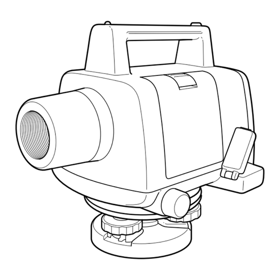
Page 8: Nomenclature And Functions
NOMENCLATURE AND FUNCTIONS Nomenclature L o c k le v e r Objective lens Battery box Leveling screw Horizontal tangent screw Base H and g rip Reticle cover AF/MF Changing knob Eyepiece ring Focusing knob Eyepiece lens Measuring key RS-232C Connector... -
Page 9: Operating Keys And Functions
Circular level mirror Height Difference key Circular level Distance/ Rod key LCD Lighting key POWER key Display Operating Keys and functions Function POWER key Power supply is on or off. Measuring key Measurement is started. • Measurement mode and Height Differ- HDif key ence mode is changed. -
Page 10: Display
Display Display Battery Power Remaining Mode Focus 1.23 45m Measurement Unit (m, ft, fi) Measurement Result Staff reading Dist Distance Height Difference Mode Display Modes Measurement Mode Meas Height Difference Mode HDif Adjustment Mode Set Mode... -
Page 11: Preparation For Measurement
PREPARATION FOR MEASUREMENT Using the Battery Box How to remove the Battery Box Push down the lock lever to remove the bttery. Lock Lever Battery box How to install the Battery Install four AA dry batteries in the battery box referring to illustration of plus and minus. - Page 12 Attaching the Instrument to the Tripod Head Take the instrument carefully out of the carrying case and place it on the tripod head. Align the tripod screw with the socket on the base of the instrument, and screw in the tripod screw until the instrument is securely fixed to the tripod head.
- Page 13 Leveling the Instrument by the circular level By using circular level mirror, the position of the bubble can be checked from the direction of the display. Use the two leveling screws furthermost from the circular level to move the bubble of the circular level vial. Rotate the screws in the direction which will shift the bubble of the circular level vial so that the bubble is located on a line perpendicular to a line running through the center of the two leveling screws being adjusted, as illus-...
-
Page 14: Focusing
Focusing You can select focusing method between manual or auto as showing illustrator for your device. Changing AF/MF To change AF to MF, push the AF/MF changing knob and turn to clock- wise. The display shows “M” during measurement. AF/MF Changing knob Manual Focus To change MF to AF, turn the AF/MF changing knob to the counterclock- wise and pull it. - Page 15 Target Sight Focusing knob Measuring key Eyepiece ring Power key Adjust to be focusing Manual focusing Turn the focusing knob to fit to the staff line in manual focusing. Auto focusing Pressing measuring key after power ON, telescope will be focus to the staff line automatically.
- Page 16 STAFF Use a staff of TOPCON made by all means. Obstructions As long as the staff is not hidden by obstructions, such as tree branches by more than 30percent, measurement can be taken. Even if the point of intersection of the cross-hair is obscured, measurements can be taken if the obstruction covers less than 30 percent of the view.
-
Page 17: Battery Supply Switch On And Changing Mode
Measuring Precaution The followings are offered to take over full functions from the unit. Set up the staff in the sufficient daylight. Even the illumination is used whole the staff should be illuminated. The minimum distance possible measurement between instrument and staff is 2m. -
Page 18: Measurement
MEASUREMENT Measurement Mode(Rod / Distance) Check the instrument to be measurement mode. Collimate the staff at the measuring point. Push the [Meas] key. Measurement is started. (Then the instrument measures rod and distance at same time.) After measurement is completed, a result is displayed. 1.2345m Push the [D/R] key to change the result to distance or rod. -
Page 19: Height Difference Mode
Height Difference Mode By using the staff, measure the height of the reference point. 1.2345m Push the [HDif] key to memorize the height of the reference point. Then the display indicates ”Recorded”. Collimate the staff of next measurement point. Push the [Meas] key. After measuring, the height difference is displayed. -
Page 20: Measuring A Horizontal Angle
Measuring a Horizontal Angle This instrument has a horizontal circle which can be used to measure horizontal angles. The horizontal circle is graduated in 1 (1g) divisions ° and is numbered every 10 (10g), with the scale calibrated from 0 °... -
Page 21: Setting Mode
SETTING MODE Items of the setting mode The following modes are available. Refer to the next page to set the items. Items Selecting Contents Set Fix Standard / Select the minimum reading Precise Standard or Precise. Display Unit Select the distance measurement m / ft / fi unit shown on the display. -
Page 22: Setting Example
Setting Example Auto Cut OFF While pressing the [D/R] key, press the power switch to set the indicator setting mode. Press the [HDif] key to change the indicator “Auto Cut off”. Press the [D/R] key. The position of the cursor indicates setting condition then. -
Page 23: Data Format
RS-232C While pressing the [D/R] key, press the power switch to set the indi- cator set mode. Press the [HDif] key to change the indicator “RS-232C”. Press the [D/R] key. The position of the cursor indicates setting con- dition then. Press the [HDif] key to select “ON”. -
Page 24: Checking And Adjustment
Checking and Adjustment Adjustment of Circular Level Check Set the instrument on the tripod and carefully center the bubble of the circular level with the three leveling screws. Revolve the telescope 180°around its vertical axis. If the bubble moves from the center, adjustment must be made as follows. Adjustment First, pick the level vial adjust screw that the bubble has moved toward. -
Page 25: Adjusting Mode
Adjusting Mode Adjust the instrument by the following steps. Set the instrument at the center between staff A and B. Center the bubble of the circular level with the three leveling screws. STAFF B STAFF A Approximately Approximately While pressing the [HDif] key, press power switch to set the indicator adjustment mode. - Page 26 Collimate the staff A and push the [Meas] key. (step3) Collimate the staff B and push the [Meas] key. (step4) The complemented value (electrical reading pattern) is displayed. +3.5mm Press the [D/R] key to set displayed electrical adjustment value, then the software indicates the rod value that should be complemented for the reticle adjustment.
-
Page 27: Error About Instrument
Start the adjustment procedure from the beginning. Focus Err Auto focus does‘t function precisely. Measure again. But auto focus doesn‘t function precisely, use manual focus. If errors still persist after attempting to clear them, contact your local TOPCON dealer. -
Page 28: Optional Accessories
Optional Accessories Aluminum Staff SA-5M (5m) Fiber Staff SG-3M/ 3F/ 3I (3m) Dome Head Aluminum Extension Leg Tripod QM-1D Dome Head Aluminum Extension Leg Tripod QM-3D Aluminum Extension Leg Tripod DM-1 Aluminum Extension Leg Tripod DM-3... -
Page 29: Specifications
SPECIFICATIONS Telescope Magnification : 26X~ Image : Erect Objective aperture : 30mm Field of view ° Resolving power : 4" Minimum focus : 0.9m Compensator Working range : ±10' Setting accuracy : ± 0.5" Height Measurement Accuracy (Standard deviation for 1km) : ±1.8mm Electrical reading (Staff SG-3M/ 3F/ 3I) - Page 30 Notes...
- Page 32 P. O. BOX 70-1002 Antelias, BEIRUT-LEBANON. Phone: 961-4-523525/961-4-523526 Fax: 961-4-521119 TOPCON CORPORATION DUBAI OFFICE Offce No. 102, Khalaf Rashd AI Nayli Bldg., 245 Abu Hail Road, Deira, Dubai, UAE Phone: 971-4-696511 Fax: 971-4-695272 31810 9021 TOPCON DL-103AF 0302 (2) NA...
Need help?
Do you have a question about the DL-103 Series and is the answer not in the manual?
Questions and answers