Table of Contents
Advertisement
Advertisement
Table of Contents

Related Manuals for Topcon RL-H2Sa


Summary of Contents for Topcon RL-H2Sa
- Page 1 0 EN T PO W ER MA NU INSTRUCTION MANUAL ROTATING LASER RL-H2Sa...
-
Page 3: Foreword
Thank you for purchasing the Topcon RL-H2Sa Rotating Laser. It is one the world’s most advanced lasers. To quickly and effectively use the RL-H2Sa, please read these brief instruc- tions carefully, and keep them in a convenient location for future reference. -
Page 4: Safety Information
Safety Information In order to ensure the safe use of this product, prevent any danger to the operator or others, or damage to property, important warnings are placed on the product and inserted in the instruction manual. We recommend that you become familiar with the meaning of these Warnings and Cautions before continuing. -
Page 5: Safety Precautions
• There is a risk of fire, electric shock or physical harm if you attempt to disassem- ble or repair the instrument yourself. Repairs are to be carried out by TOPCON or an authorized dealer ONLY! • Laser beams can be dangerous and can cause eye injury if used incorrectly. - Page 6 CAUTION Use of controls, adjustment to the laser, or the performing of any procedures other than those specified herein may result in hazardous radiation exposure. DO NOT allow anyone to work directly in the path of the laser beam. Always make sure the laser is operating above the height of your crews heads. Exposure to laser light may cause momentary blindness.
-
Page 7: User Precautions
User Precautions Always wear protective clothing (safety shoes, helmet, etc.) when operating. Exceptions from Responsibility The user of this product is expected to follow all operating instructions and make periodic checks of the product’s performance. The manufacturer, or its representatives, assumes no responsibility for results of a faulty or intentional usage or misuse including any direct, indirect, consequential damage, and loss of profits. -
Page 8: Laser Safety
As per the said standard, this product is classified as a “Class 3A (IIIA) Laser Product”. This is a simple product to operate and does not require training from a laser safety officer. In case of any failure, do not disassemble the instrument. Contact TOPCON or your TOP- CON dealer. -
Page 9: Table Of Contents
Horizontal Rotation Cone Error ....31 Standard System Components ....8 Grade Setting Error ........32 Nomenclature and Functions ...9 (1) Checking ..........32 RL-H2Sa ............9 Storage Precautions ......35 Control Panel ..........10 Standard / Optional Accessories ..36 Basic Operation .........11 Laser sensor holder model 5 .... -
Page 10: Standard System Components
Standard System Components 1 RL-H2Sa ..................1pc. 2 BT-51Q (Ni-MH) Rechargeable battery ..........1pc. 3 DB-51C Rechargeable battery holder ........... 1pc. 4 AD-9B/7C AC/DC converter ..............1pc. 5 LS-70B Laser Sensor ................1pc. 6 Laser Sensor holder, model 3 ............... 1pc. -
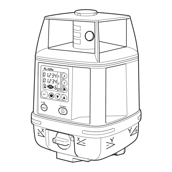
Page 11: Nomenclature And Functions
Nomenclature and Functions RL-H2Sa Grade alignment sights Rotary head Beam aperture Handle Control Panel x1 00 EN T P O W E M AN U Battery holder Battery compartment lock... -
Page 12: Control Panel
Control Panel Rotation speed Masking direction indicator X-axis key X-axis grade display Y-axis key (Arrow key for Mask quadrant 4) Y-axis grade display Rotation control key Auto leveling indicator (Arrow key for Mask quadrant 2) Battery indicator Arrow keys Enter key •... -
Page 13: Basic Operation
Basic Operation Set the RL-H2Sa on a tripod or flat surface. (See "Instrument Set-up Procedure " on page 12.) Turn the instrument ON and enter a grade if desired. (See "Entering Grade " on page 18.) Set beam rotation to the desired speed. -
Page 14: Preparation And Functions
For battery installation instructions, see "Maintaining Power Sources " on page 22. Instrument Set-up Procedure Set the instrument on any smooth surface that is within ±5° of true level. The RL-H2Sa auto-level system will not function if the unit is placed more that 5° out of level. For best operation, it is recommended that it be mounted to a tripod. -
Page 15: Battery Warning Indicator
Battery Warning Indicator The Battery warning indicator indicates the battery power remaining. Battery is sufficient. The power is low, but laser is still usable. In this state, the laser will transmit the battery warning signal to laser sensor. AC/DC converter AD-9B or AD-7C is available for continuing the operation. Dead batteries. -
Page 16: Auto-Leveling Lamp
Auto-leveling lamp Flashing : Auto-leveling is in process. When automatic leveling is almost complete, the flashing rate will be slow. The head will not rotate and the laser beam will not emit during the auto-leveling process. ON Solid:Auto-leveling is complete. The rotary head is active and emits the laser beam. -
Page 17: Inclination Warning
Inclination Warning If the instrument is inclined out of automatic grading range (usually approximately ±5°, but ±2° according to the set grades). The Auto-leveling lamp will flash and the grades will disappear. Set the instrument as hori- zontally as possible and turn off/on the instrument again. (This warning may be displayed about six minutes or more after powering ON.) Blinking... -
Page 18: Changing Rotation Speed
Changing rotation speed Press Rotation Control key to activate rotation speed mode. Select the rota- tion speed 300 r.p.m, 600 r.p.m or 900 r.p.m by pressing the arrow keys. Press the Enter key to accept the setting. Height Alert function When auto-leveling and height alert function are active, this function prevents the instrument from operating if it is disturbed. -
Page 19: Aligning Direction Of Grade
Aligning Direction of Grade When using the laser with a percent of grade entered, the laser must be properly aligned so the slope of the laser beam is parallel to the desired direction of grade. The sighting collimator on top of the instrument is cali- brated to the grade axis of the laser beam. -
Page 20: Entering Grade
Entering Grade The laser beam can be sloped in either the X or Y axis (single slope) or both axes (com- pound slope). Grade range: Single axis: -8.000 to +8.000%, Dual axes: |X| + |Y| ≤ 10.000% Compound slope Single Axis Dual Axes Plus (+) Minus (-) -
Page 21: How To Enter Grade
How to enter grade Setting example: Grade toward X-axis -2.800%, Y-axis -3.456% Operating procedure Operation Display Turn the instrument on by pressing the power con- Power ON trol pad. Auto-leveling will start. Press the [ X] key to activate grade entry. The position of the second figure to the left of the decimal point will blink. - Page 22 Press the [ Y] key to to activate grade entry. The position of the second figure to the left of the decimal point will blink. Press the [Y] key to activate the first figure to the left of the decimal point. [ ] 3times Press the [ ] key three times to set ‘3’.
-
Page 23: Masking (Laser Beam Shutter)
Masking (Laser beam shutter) The RL-H2Sa features electronic beam “masking” to prevent the beam from transmitting on one or multiple sides of the instrument. This can be useful to eliminate duplicate laser beams on job sites where more than one laser may be in use. -
Page 24: Maintaining Power Sources
Maintaining Power Sources Installing Insert the BT-51Q rechargeable battery into the instrument. Place the DB-51C rechargeable battery holder firmly into the instrument and turn the bat- tery cover knob to “LOCK”. Charging Plug the AC/DC converter (AD-9B or AD-7C) into the charger jack on the DB-51C rechargeable battery holder. - Page 25 Automatic protection feature; In case of overcharge or high or low temperature state exceed- ing charging range, charging will be stopped or changed to protect battery. The RL-H2Sa can be charged while using the laser. Note Alkaline batteries can be used with the DB-51C rechargeable battery holder.
-
Page 26: Checking And Adjusting Calibration
The Horizontal Calibration can be easily checked and, in most cases, adjustments can be made by the user. Horizontal Rotation Cone and Grade Setting Error can be checked by the user. However, if an error is found, adjustments must be made by a Topcon service facility. Horizontal Calibration... - Page 27 Turn the unit on and allow auto-leveling to complete. Con - firm that the grade is set to 00.000%. Put the laser sensor in fine detection mode by pressing the mode switch.(See page 37.) Position the sensor so that it “finds” the rotating laser beam and signals “on-grade”...
-
Page 28: Adjusting Calibration
If the distance is greater than 5mm (0.2 inches), adjust as follows. Repeat procedure for the Y axis. Note • Please contact your Topcon dealer if the distance between the first and sec- ond mark exceeds ±40mm (1.6 inches). (2) Adjusting Calibration To calibrate the X axis: Press the Power button once to turn off the laser. - Page 29 Note • When the instrument has auto-leveled, the “POS 1” will stop flashing. When the sensor signals “on-grade”, secure its position. When Beam is Move Level Sensor Up Detected, Fix Level or Down Until Beam is Sensor. Detected. 50m (160 feet) 50m (160 feet) Press the ENT key.
- Page 30 When “POS 2” is displayed, rotate the instrument 180 degrees; the instrument will self- level. When the instrument has auto-leveled, the “POS 2” will stop flashing. Note • When rotating the instrument, avoid knocking it off level or changing height. PRESS BUTTON TO MOVE BEAM...
- Page 31 After a short time, “CAL END” will appear. PRESS ENTER Note • If the error is greater than the self-correction range, “E72” error code will dis- play and LEDs will blink alternately. Contact your Topcon dealer.
- Page 32 Turn Off the instrument by pressing the Power key. Turn the power ON again and follow the checking procedure again to confirm that proper calibration has been completed. Repeat the checking and, if necessary, the adjusting procedure for the Y-axis. If the Y-axis requires adjustment, begin at Step 1 on page 26.
-
Page 33: Horizontal Rotation Cone Error
Measure the distance between the first and second marks on each wall. If the difference between each set of marks is less than 4mm (5/32 of an inch), no error exists. Note • If the error is greater than 4mm ( 5/32 of an inch), contact your Topcon dealer. -
Page 34: Grade Setting Error
Grade Setting Error Perform the following check only after completing "Horizontal Calibration" and “Hori- zontal Rotation Cone Error” procedures. (1) Checking Note • Due to the accuracy required to perform this check, the rod used in this pro- cedure must be graduated in millimeters. Securely position two nails or stakes exactly 30m (93 ft) apart. - Page 35 beam in millimeters at Nail 1 and Nail 2. Designate the elevation at Nail 1 as “h1”, at Nail 2 as “h2”. Set X-axis grade to 1.000%. Again, read the elevation of the laser beam in millimeters at Nail 1 and Nail 2. Designate these elevations as “h3” at Nail 1, and “h4” at Nail 2. Nail 1 Nail 2 Using the millimeter elevation readings for h1, h2, h3 and h4, and converting the 30mm...
- Page 36 Note • If the calculated result is out of the range, contact your dealer or Topcon. Example; h1 = 1370; h2 = 1390; h3 = 1362; h4 = 1080 x(%)= (1390-1080)-(1370-1362) x 100 30000 x(%)= 310 - 8 x 100 30000 x(%)= 0.010066 x 100...
-
Page 37: Storage Precautions
Storage Precautions Always clean the instrument after use. Use a clean cloth, moistened with a neutral detergent or water. Never use an abrasive cleaner, ether, thinner benzene, or other solvents. Always make sure instrument is completely dry before storing. Dry any moisture with a soft, clean cloth. -
Page 38: Standard / Optional Accessories
Standard / Optional Accessories Laser sensor holder model 3 Laser sensor holder model 5 Clamp knob Clamp knob POWER Laser sensor Laser sensor holder model 3 holder model 5 Laser sensor Laser sensor Holder Model 5 allows the laser sensor to be moved up or down on the rod by squeezing the spring-loaded clamp on its back side without removing the sensor from the rod. -
Page 39: Ls-70A Laser Sensor
LS-70B Laser Sensor LS-70A Laser Sensor Beam receiving window Beam receiving window Indicator Indicator On-Grade index On-Grade index On-Grade index On-Grade precision switch Buzzer sound Two on-grade precision switch options are available, normal precision and (Quite/Loud/OFF) high precision. By Power switch pressing this switch, the precision options are switched alternately. - Page 40 flash until the sensor detects normal beam rotation from the laser. To obtain nor- On-Grade indicator mal beam rotation, the RL-H2Sa must be (Audio signal: Continuous beep sound) turned off then back on. Then check that beam height has not changed (See page Below grade indicator 16).
- Page 41 Detective range (LS-70A/70B) Replacing Battery (LS-70A/70B) Press the lid in the direction of the arrow HIGH NORMAL to lift. LS-70A ±2mm/±.0064mm Remove the battery and ±1mm/±.0032ft (4mm/.013 ft width) (2mm/.0064ft width) replace with a new 9v LS-70B ±1mm/±.0032ft alkaline battery. (2mm/.0064ft width) Press the lid down and ±5mm/±.016ft...
-
Page 42: Scope Model 3
Scope Model 3 The optional scope replaces the sighting collimator (see page 17) on top of the instrument and provides greater accuracy in aligning the laser to the direction of grade. The scope can be swiveled and locked in place so its aimed toward any of the four beam axes. Using the scope, follow the steps on page 17 to align the instrument. -
Page 43: Rechargeable Battery Holder Db-51
Dry battery holder DB-51 How to replace dry batteries Remove the battery holder DB-51 by turning the battery compartment lock to “OPEN”. Remove the old batteries and replace with four (4) new “D” cell alkaline batteries making sure each is placed in the proper direction as indicated. -
Page 44: Error Code
Calibration error is greater than self- again and perform the calibration correction range. again. Abnormal operation of internal Turn the instrument OFF and ON memory system detected. again. If errors still persist after attempting to clear them, contact your dealer or Topcon. -
Page 45: Specifications
Specifications RL-H2Sa Auto-leveling range ±5° Beam detecting range 2m–700m diameter (6ft–2,300ft) (When using with LS-70A/70B) Laser source Laser diode (visible) Laser class Class 3A laser product Rotation speeds Selectable : 300, 600, 900 r.p.m. Grade setting range Single axis : -8.000% to +8.000% Dual axes : |X| + |Y| ≤... -
Page 46: Laser Sensor Ls-70A/B
Laser Sensor LS-70A/B Beam detection window 50mm (2.0 in) Beam detection precision High precision:±1mm(±0.04 in) Normal precision:±2mm(±0.08 in) Beam detection indication Liquid crystal and buzzer Power source DC 9V alkaline (dry) battery Auto shut-off delay Approx. 30 minutes without beam detection. Operating temperature -20°C to +50°C (-4°F to +122°F) Continuous operating time at +20°C (68°F) - Page 48 TOPCON AMERICA CORPORATION TOPCON (GREAT BRITAIN) LTD. CORPORATE OFFICE HEAD OFFICE Topcon House Kennet Side, Bone Lane Newbury Berkshire RG14 5PX 37 West Century Road, Paramus, New Jersey 07652, U.S.A. U.K. Phone: 001-44-1635-551120 Fax: 001-44-1635-551170 Phone: 201-261-9450 Fax: 201-387-2710 www.Topcon.com TOPCON SINGAPORE PTE.
Need help?
Do you have a question about the RL-H2Sa and is the answer not in the manual?
Questions and answers