Sign In
Upload
Download
Table of Contents
Contents
Add to my manuals
Delete from my manuals
Share
URL of this page:
HTML Link:
Bookmark this page
Add
Manual will be automatically added to "My Manuals"
Print this page
×
Bookmark added
×
Added to my manuals
Manuals
Brands
Topcon Manuals
Laser Level
DT-200 series
Instruction manual
Topcon DT-200 series Instruction Manual
Digital theodolite
Hide thumbs
1
2
3
4
5
6
7
8
9
Table Of Contents
10
11
12
13
14
15
16
17
18
19
20
21
22
23
24
25
26
27
28
29
30
31
32
33
34
35
36
37
38
39
40
41
42
43
44
45
46
47
48
49
50
51
52
53
page
of
53
Go
/
53
Contents
Table of Contents
Bookmarks
Table of Contents
Foreword
General Handling Precautions
Display for Safe Use
Safety Cautions
Laser Safety
User
Exceptions from Responsibility
Table of Contents
Contents
Standard Set Composition
1 Nomenclature and Functions
Nomenclature
Display
Operating Keys
2 Preparation for Measurement
Setting Instrument up for Measurement
Power Switch Key on
Battery Level Indicator
Vertical Angle Tilt Correction
Serial Signal RS-232C Connector
3 Measurement
Measuring Horizontal Angle Right and Vertical Angle
Switching Horizontal Angle Right / Left
Measuring from the Required Horizontal Angle
Vertical Angle % Display
Repetition Angle Measurement
Stadia Surveying
4 How to Operate the Laser
5 The Other Functions
Buzzer Sounding for Horizontal Angle 90° Increments
Compasses (Vertical Angle)
Auto Cut off
Setting Minimum Angle Reading
Detach / Attach of Tribrach
6 Selecting Mode
Items of the Selecting Mode
How to Set the Selecting Modes
7 Handling Power Source
For Removing
Replace the Battery (DB-35)
For Installing
8 Check and Adjustment
Checking /Adjusting the Plate Level
Checking and Adjusting the Circular Level
Adjustment of the Vertical Cross-Hair
Collimation of the Instrument
Checking and Adjusting the Optical Plummet Telescope
Adjustment of Vertical Angle 0 Datum
Adjustment of Laser Beam
9 Storage Precautions
11 Optional Accessories
12 Error Display
Specifications
Advertisement
Quick Links
1
General Handling Precautions
2
Setting Instrument up for Measurement
3
Measuring Horizontal Angle Right and Vertical Angle
4
Specifications
Download this manual
INSTRUCTION MANUAL
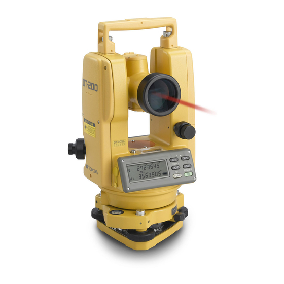
DIGITAL THEODOLITE
DT-200/200L
SERIES
Table of
Contents
Previous
Page
Next
Page
1
2
3
4
5
Advertisement
Table of Contents
Need help?
Do you have a question about the DT-200 series and is the answer not in the manual?
Ask a question
Questions and answers
Related Manuals for Topcon DT-200 series
Laser Level Topcon DL-502 Instruction Manual
Digital level dl-500 series (86 pages)
Laser Level Topcon DL-503 Instruction Manual
Digital level dl-500 series (86 pages)
Laser Level Topcon DL-201/2007 User Manual
(106 pages)
Laser Level Topcon DL-501 Instruction Manual
Digital level (134 pages)
Laser Level Topcon DT-205 Instruction Manual
Digital theodolite (53 pages)
Laser Level Topcon DT-205L Instruction Manual
Digital theodolite (53 pages)
Laser Level Topcon DT-209 Instruction Manual
Digital theodolite (53 pages)
Laser Level Topcon DL-103 Series Instruction Manual
Digital level (35 pages)
Laser Level Topcon DT-300 Series Instruction Manual
Digital theodolite (47 pages)
Laser Level Topcon DT-307 Instruction Manual
Digital theodolite (47 pages)
Laser Level Topcon DT-307L Instruction Manual
Digital theodolite (47 pages)
Laser Level Topcon RL-200 2S Instruction Manual
Rotating laser (70 pages)
Laser Level Topcon RL-SV2S Instruction Manual
Rotating laser (67 pages)
Laser Level Topcon RL-VH4G Instruction Manual
Rotating laser (50 pages)
Laser Level Topcon RL-H3C Instruction Manual
Rotating laser (29 pages)
Laser Level Topcon RL-H2Sa Instruction Manual
Rotating laser (48 pages)
This manual is also suitable for:
Dt-205
Dt-200l series
Dt-209p
Dt-207
Dt-205l
Dt-207l
...
Show all
Dt-209l
Dt-209
Table of Contents
Save PDF
Print
Rename the bookmark
Delete bookmark?
Delete from my manuals?
Login
Sign In
OR
Sign in with Facebook
Sign in with Google
Upload manual
Upload from disk
Upload from URL


Need help?
Do you have a question about the DT-200 series and is the answer not in the manual?
Questions and answers