Table of Contents
Advertisement
Advertisement
Table of Contents

Related Manuals for Topcon DT-205L


Summarization of Contents
General Handling Precautions
Setting the Instrument on a Tripod
Guidance on properly setting the instrument on a tripod to maintain measuring precision.
Installing the Tribrach
Instructions on correctly installing the tribrach to ensure measuring precision and stability.
Protecting the Instrument from Shocks
Recommendations for protecting the instrument from shocks during transport to prevent damage or malfunction.
Carrying the Instrument
Instruction on the proper method for carrying the instrument using its handgrip.
Avoiding Extreme Heat Exposure
Warning against leaving the instrument in extreme heat to prevent adverse effects on its performance.
Managing Sudden Temperature Changes
Advice on acclimating the instrument to ambient temperature and shading it from direct sunlight for precision.
Battery Level Check and Storage
Instructions on checking battery levels before operation and proper storage with batteries removed.
Display for Safe Use
Safety Cautions
Essential warnings and precautions to prevent injury, fire, electric shock, and damage to the instrument.
Laser Safety
Laser Safety Labels
Information on identifying and replacing caution labels related to laser beam safety.
Nomenclature and Functions
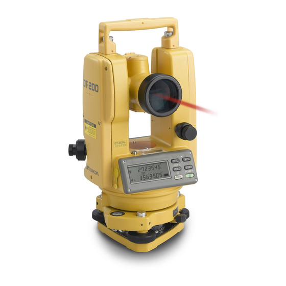
Nomenclature
Identification and labeling of the instrument's various parts and components.
Display Overview
Explanation of the instrument's display window and its various display marks.
Operating Keys
Description of the instrument's operating keys and their respective functions.
Preparation for Measurement
Setting Instrument Up for Measurement
Detailed steps for setting up the instrument on a tripod and leveling it using circular and plate levels.
Power Switch ON Procedure
Instructions for turning on the instrument's power switch and confirming initial status.
Battery Level Indicator
Explanation of the battery power indicator and its meaning for operation and charging.
Vertical Angle Tilt Correction
Details on automatic vertical angle correction for mislevelment and when manual leveling is required.
RS-232C Connector
Information about the RS-232C connector for connecting the instrument to a computer for data transfer.
Measurement Procedures
Measuring Horizontal and Vertical Angles
Step-by-step guide on how to measure horizontal and vertical angles using the instrument.
Switching Horizontal Angle Modes
Instructions on switching between Horizontal Angle Right (HR) and Horizontal Angle Left (HL) modes.
Measuring from a Set Horizontal Angle
Procedure for holding a horizontal angle and starting measurement from that held angle.
Vertical Angle Percentage Display
How to switch to and interpret the vertical angle percentage display mode.
Repetition Angle Measurement
Detailed steps for performing repetition angle measurements to improve accuracy.
Stadia Surveying
Explanation of how to use the instrument for distance measurement using stadia hairs.
Other Functions
90° Horizontal Angle Buzzer
Explanation of the buzzer sound feature that activates at 90° horizontal angle increments.
Vertical Angle Compass Display
Information on the vertical angle scale display and how to set the compass function.
Auto Power Cut Off
Details on the automatic power-off function after a period of inactivity.
Setting Minimum Angle Reading
How to select the minimum display unit for angle measurement for different models.
Selecting Modes
Selecting Mode Items
Lists and describes the various items that can be configured in Selecting Mode 1.
Selecting Mode 2 Items
Lists and describes the various items that can be configured in Selecting Mode 2.
How to Set Selecting Modes
Step-by-step guide on how to set Selecting Mode 1, including sample settings.
Handling Power Source
Removing the Battery
Procedure for removing the battery from the instrument.
Replacing the Battery
Detailed instructions for replacing the DB-35 battery, including proper orientation and care.
Installing the Battery
Procedure for installing the battery into the instrument until it clicks into position.
Check and Adjustment
Pointers on Adjustment
Key points and recommendations for performing adjustments correctly and effectively.
Notes on the Tribrach
Important notes regarding loose leveling screws and slack between leveling screws and the base.
Checking and Adjusting the Plate Level
Procedure for checking and adjusting the plate level to ensure it is perpendicular to the vertical axis.
Checking and Adjusting the Circular Level
Steps for checking and adjusting the circular level using capstan adjustment screws.
Adjusting the Vertical Cross-hair
Detailed procedure for adjusting the vertical cross-hair to be perpendicular to the horizontal axis.
Collimation of the Instrument
Procedure to ensure the line of sight is perpendicular to the horizontal axis for accurate measurements.
Adjusting the Optical Plummet Telescope
Steps to ensure the optical plummet telescope's line of sight aligns with the vertical axis.
Adjustment of Vertical Angle 0 Datum
Procedure for adjusting the vertical angle 0 datum, critical for determining the instrument's coordinate origin.
Adjustment of Laser Beam
Instructions for aligning the laser spot with the cross-hair intersection.
Need help?
Do you have a question about the DT-205L and is the answer not in the manual?
Questions and answers