Sign In
Upload
Download
Table of Contents
Contents
Add to my manuals
Delete from my manuals
Share
URL of this page:
HTML Link:
Bookmark this page
Add
Manual will be automatically added to "My Manuals"
Print this page
×
Bookmark added
×
Added to my manuals
Manuals
Brands
Topcon Manuals
Laser Level
DT-300 Series
Instruction manual
Topcon DT-300 Series Instruction Manual
Digital theodolite
Hide thumbs
1
2
3
4
5
6
7
8
9
10
11
12
13
14
15
16
17
18
19
20
21
22
23
24
25
26
27
28
29
30
31
32
33
34
35
36
37
38
39
40
41
42
43
44
45
46
Table Of Contents
47
page
of
47
Go
/
47
Contents
Table of Contents
Bookmarks
Table of Contents
How to Read this Manual
Precautions for Safe Operation
Laser Safety Information
Product Outline
Parts of the Instrument
Basic Key Operation
Display Functions
Using the Battery
Installing the AA Batteries
Setting up the Instrument
Vertical Angle Tilt Correction
Power On/Off
Angle Measurement
Switching Horizontal Angle Right/Left
Measuring from the Required Horizontal Angle
Vertical Angle % Display
Repetition Angle Measurement
Stadia Surveying
Other Functions
Selecting Mode
How to Set the Selecting Modes
Checks and Adjustments
Plate Level
Circular Level
Optical Plummet
Laser Beam
Optional Accessories
Error Display
Specifications
Advertisement
Quick Links
1
How to Read this Manual
2
Parts of the Instrument
3
Basic Key Operation
4
Setting up the Instrument
5
How to Set the Selecting Modes
6
Checks and Adjustments
7
Specifications
Download this manual
COVER
INSTRUCTION MANUAL
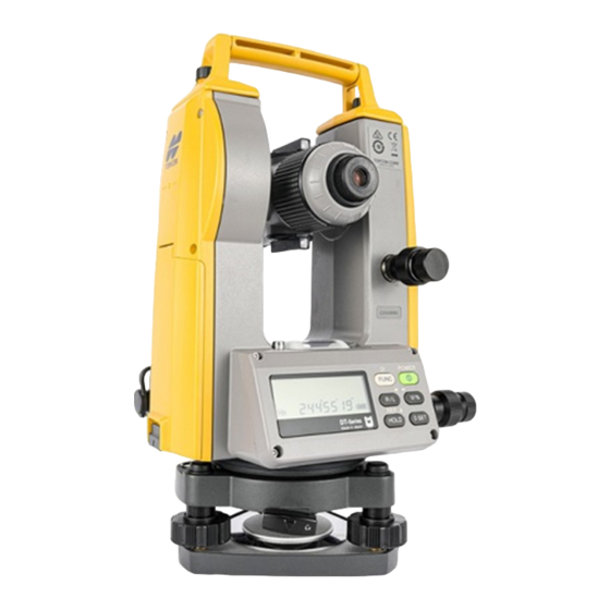
DIGITAL THEODOLITE
DT-300 series
1037074-02-B
Table of
Contents
Previous
Page
Next
Page
1
2
3
4
5
Advertisement
Table of Contents
Need help?
Do you have a question about the DT-300 Series and is the answer not in the manual?
Ask a question
Questions and answers
Related Manuals for Topcon DT-300 Series
Laser Level Topcon DL-502 Instruction Manual
Digital level dl-500 series (86 pages)
Laser Level Topcon DL-503 Instruction Manual
Digital level dl-500 series (86 pages)
Laser Level Topcon DL-201/2007 User Manual
(106 pages)
Laser Level Topcon DL-501 Instruction Manual
Digital level (134 pages)
Laser Level Topcon DT-200 series Instruction Manual
Digital theodolite (53 pages)
Laser Level Topcon DT-205 Instruction Manual
Digital theodolite (53 pages)
Laser Level Topcon DT-205L Instruction Manual
Digital theodolite (53 pages)
Laser Level Topcon DT-209 Instruction Manual
Digital theodolite (53 pages)
Laser Level Topcon DL-103 Series Instruction Manual
Digital level (35 pages)
Laser Level Topcon DT-307 Instruction Manual
Digital theodolite (47 pages)
Laser Level Topcon DT-307L Instruction Manual
Digital theodolite (47 pages)
Laser Level Topcon RL-200 2S Instruction Manual
Rotating laser (70 pages)
Laser Level Topcon RL-H3CS Instruction Manual
Rotating laser (2 pages)
Laser Level Topcon RL-H2Sa Instruction Manual
Rotating laser (48 pages)
Laser Level Topcon RL-SV1S Instruction Manual
Rotating laser (84 pages)
Laser Level Topcon RL-H3A Instruction Manual
Rotating laser (35 pages)
This manual is also suitable for:
Dt-302
Dt-305
Dt-305l
Dt-307
Dt-307l
Dt-309f
...
Show all
Dt-309g
Dt-309lg
Table of Contents
Save PDF
Print
Rename the bookmark
Delete bookmark?
Delete from my manuals?
Login
Sign In
OR
Sign in with Facebook
Sign in with Google
Upload manual
Upload from disk
Upload from URL


Need help?
Do you have a question about the DT-300 Series and is the answer not in the manual?
Questions and answers