Table of Contents
Advertisement
Quick Links
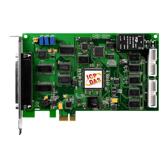
PCI-1002 Series Card
User Manual
12-bit, 110 kS/s or 44 kS/s Multi-function Board
S
UPPORTS
Board includes PCI-1002L, PCI-1002H, PCI-1002LU, PCI-1002HU, PEX-1002L and
PEX-1002H.
W
ARRANTY
All products manufactured by ICP DAS are warranted against defective materials
for a period of one year from the date of delivery to the original purchaser.
W
ARNING
ICP DAS assumes no liability for damages consequent to the use of this product.
ICP DAS reserves the right to change this manual at any time without notice. The
information furnished by ICP DAS is believed to be accurate and reliable. However,
no responsibility is assumed by ICP DAS for its use, nor for any infringements of
patents or other rights of third parties resulting from its use.
C
OPYRIGHT
Copyright © 2018 by ICP DAS. All rights are reserved.
T
RADEMARK
Names are used for identification only and may be registered trademarks of their
respective companies.
C
US
ONTACT
If you have any question, please feel to contact us at:
service@icpdas.com; service.icpdas@gmail.com
We will give you quick response within 2 workdays.
Version 3.0, Jun. 2018
Advertisement
Table of Contents

Related Manuals for ICP DAS USA PCI-1002L


Summary of Contents for ICP DAS USA PCI-1002L
- Page 1 User Manual 12-bit, 110 kS/s or 44 kS/s Multi-function Board Version 3.0, Jun. 2018 UPPORTS Board includes PCI-1002L, PCI-1002H, PCI-1002LU, PCI-1002HU, PEX-1002L and PEX-1002H. ARRANTY All products manufactured by ICP DAS are warranted against defective materials for a period of one year from the date of delivery to the original purchaser.
-
Page 2: Table Of Contents
ABLE OF ONTENTS ..................................3 ACKING INTRODUCTION ..............................4 EATURES ................................5 PECIFICATIONS ..............................6 1.2.1 PCI-1002L/1002H/1002LU/1002HU ......................6 1.2.2 PEX-1002L/1002H ............................7 1.2.3 Analog Input Range ............................8 1.2.4 AD Trigger Methods ............................8 1.2.5 Interrupt Channel ............................9 1.2.6 Programmable Timer/Counter ........................ - Page 3 PCI-1002 Series Card 12-bit, 110 kS/s or 44 kS/s Multi-function Board I/O REGISTER ADDRESS ..........................41 I/O A OW TO IND THE DDRESS I/O A ......................... 41 DDRESS ............................45 6.2.1 Section1 ................................. 46 6.2.2 Section2 ................................. 47 FUNCTION OPERATIONS ..........................52 I/O ...............................
-
Page 4: Packing List
PCI-1002 Series Card 12-bit, 110 kS/s or 44 kS/s Multi-function Board Packing List The shipping package includes the following items: One PEX/PCI-1002 series card hardware One printed Quick Start Guide One Software Utility CD One CA-4002 D-Sub Connect Note: If any of these items is missing or damaged, contact the dealer from whom you purchased the product. Save the shipping materials and carton in case you need to ship or store the product in the future. -
Page 5: Introduction
PCI-1002L/H. Users can replace the PCI-1002L/H by the PCI-1002LU/HU and PEX-1002LU/HU directly without software/driver modification. The PCI-1002L/H supports 5 V PCI bus and PCI-1002LU/HU supports 3.3 V/5 V PCI bus, while the PEX-1002L/H supports PCI Express bus. The PCI-1002 series is a family of AD board and features low-gain 110 kS/s or high-gain 44 kS/s analog input. -
Page 6: Features
PCI-1002 Series Card 12-bit, 110 kS/s or 44 kS/s Multi-function Board 1.1 Features Bus: 5 V PCI (Peripherals Component Interface) bus for PCI-1002L/H • Universal PCI card, supports both 5 V and 3.3 V PCI bus for PCI-1002LU/HU • PCI Express card, supports PCI Express x1 for PEX-1002L/H •... -
Page 7: Specifications
PCI-1002 Series Card 12-bit, 110 kS/s or 44 kS/s Multi-function Board 1.2 Specifications 1.2.1 PCI-1002L/1002H/1002LU/1002HU Model Name PCI-1002L PCI-1002H PCI-1002LU PCI-1002HU (Phased-out) (Phased-out) Analog Input Channels 32 single-ended/16 differential AD Converter 12-bit, 8 μs Conversion time Sampling Rate 110 kS/s. -
Page 8: Pex-1002L/1002H
PCI-1002 Series Card 12-bit, 110 kS/s or 44 kS/s Multi-function Board 1.2.2 PEX-1002L/1002H Model Name PEX-1002L PEX-1002H Analog Input Channels 32 single-ended/16 differential AD Converter 12-bit, 8 μs Conversion time Sampling Rate 110 kS/s. 44 kS/s. FIFO Size Over voltage Protection Continuous +/-35 Vp-p Input Impedance 10 MΩ/6 pF... -
Page 9: Analog Input Range
PCI-1002 Series Card 12-bit, 110 kS/s or 44 kS/s Multi-function Board 1.2.3 Analog Input Range Model PCI-1002L/LU and PEX-1002L (Low-Gain) Gain Bipolar ±10 V ±5 V ±2.5 V ±1.25 V Sampling Rate Max. 100 kS/s. Model PCI-1002H/HU and PEX-1002H (High-Gain) -
Page 10: Interrupt Channel
PCI-1002 Series Card 12-bit, 110 kS/s or 44 kS/s Multi-function Board 1.2.5 Interrupt Channel Interrupt: INTA (Automatically assigned by PCI-initiator). Enable/Disable: Via PCI control register and add-on control register. Interrupt source: (Selected by on-board control register) 1. AD conversion interrupt. 2. -
Page 11: The Block Diagrams
PCI-1002 Series Card 12-bit, 110 kS/s or 44 kS/s Multi-function Board 1.3 The Block Diagrams Here’s the block diagram of PCI-1002 series: X86 System EPROM PCI Interface System Status Local System Controller Control Interrupt Digital Inputs 16 bits DI 16 bits DO Digital Outputs Pacer 4MHz... -
Page 12: Hardware Configuration
PCI-1002 Series Card 12-bit, 110 kS/s or 44 kS/s Multi-function Board Hardware Configuration 2.1 Board Layout Figure 2.1 and Figure 2.2 shows the layout of the PEX-1002L/H and PCI-1002LU/HU boards and the locations of the configuration jumper and connector for signal wiring. ... - Page 13 PCI-1002 Series Card 12-bit, 110 kS/s or 44 kS/s Multi-function Board PCI-1002LU/HU. Figure 2-2 CON1 16-channel Digital Output CON2 16-channel Digital Input Refer to Section 2.8 “Pin Assignments” more details. The terminal for the AD and DA converters for CON3 voltage input/output Refer to...
-
Page 14: Jp1: Ad Input T
PCI-1002 Series Card 12-bit, 110 kS/s or 44 kS/s Multi-function Board 2.2 JP1: AD Input Type Selection This jumper is used to select the analog input type. For single-ended inputs, connect pin1, 3 and pin2, 4. For differential inputs, pin3, 5 and pin4, 6 should be connected. The configuration is illustrated in the figure below. -
Page 15: Card Id Switch
PCI-1002 Series Card 12-bit, 110 kS/s or 44 kS/s Multi-function Board 2.4 Card ID Switch The PEX-1002L/H has a Card ID switch (SW1) with which users can recognize the board by the ID via software when using two or more PEX-1002L/H cards in one computer. The default Card ID is 0x0. Note that the Card ID function is only supported by For detail SW1 Card ID settings, refer to Table 2-1. -
Page 16: Jp2: Di Port Settings
PCI-1002 Series Card 12-bit, 110 kS/s or 44 kS/s Multi-function Board 2.5 JP2: DI Port Settings (Pull-High/Low) This DI ports can be pull-high or pull-low that is selected by JP2. The pull-high/low jumpers of the card allow user to predefine the DI status instead of floating when the DI channels are unconnected Note: This function only supports or broken. -
Page 17: Ad Input Signal
PCI-1002 Series Card 12-bit, 110 kS/s or 44 kS/s Multi-function Board 2.7 AD Input Signal Connection The PCI-1002 series card can measure either single-ended or differential-type analog input signals. The user must decide which mode is most suitable for measurement purposes. Please refer to the Section 2.2 “JP1: AD Input Type Selection”to see how to configure the JP1 jumper based on your analog input type. - Page 18 PCI-1002 Series Card 12-bit, 110 kS/s or 44 kS/s Multi-function Board Figure 2-3: Differential input with grounded source (Right way) A/D CH0 HI Es 1 A/D CH 0 LO A.GND 1 A/D CH n HI Es n A/D CHn LO A.GND n ...
- Page 19 PCI-1002 Series Card 12-bit, 110 kS/s or 44 kS/s Multi-function Board Figure 2-4: Single-ended input with floating signal source A/D CH0 A/D CH1 A/D CH n AGND Figure 2-5: Differential input with floating thermocouple signal A/D CH 0 HI Note: If the input signal is not A/D CH 0 LO thermocouple, the user should...
- Page 20 PCI-1002 Series Card 12-bit, 110 kS/s or 44 kS/s Multi-function Board Figure 2-6: Differential input with floating signal source A/D CH 0 HI Es 1 A/D CH 0 LO A.GND A/D CH n HI Es n A/D CH n LO A.GND ...
- Page 21 PCI-1002 Series Card 12-bit, 110 kS/s or 44 kS/s Multi-function Board Figure 2-8: Signal Shielding Signal shielding connections in Figure 2-3 Figure 2-7 are all the same, as show in the below figure. Use a single-point connection to frame ground (not A.GND or D.GND) PCI-1002 Series card A.GND D.GND...
-
Page 22: Pin Assignments
PCI-1002 Series Card 12-bit, 110 kS/s or 44 kS/s Multi-function Board 2.8 Pin Assignments CON1 and CON2: Digital Output and Digital Input connector User Manual, Ver. 3.0, Jun. 2018, PMH-015-30, Page: 21... - Page 23 PCI-1002 Series Card 12-bit, 110 kS/s or 44 kS/s Multi-function Board CON3: Single-ended input and Differential input for Analog Input connector Differential Input Single-Ended Input User Manual, Ver. 3.0, Jun. 2018, PMH-015-30, Page: 22...
-
Page 24: Hardware Installation
PCI-1002 Series Card 12-bit, 110 kS/s or 44 kS/s Multi-function Board Hardware Installation Note: It is recommended that the driver is installed before installing the hardware as the computer may need to be restarted once the driver is installed in certain operating systems, such as Windows 2000 or Windows XP, etc. Installing the driver first helps reduce the time required for installation and restarting the computer. - Page 25 PCI-1002 Series Card 12-bit, 110 kS/s or 44 kS/s Multi-function Board Step 3: Shut down and switch off the power to the computer, and then disconnect the power supply. Step 4: Remove all covers from the computer. Step 5: Select a vacant PCI/PCI Express slot. User Manual, Ver.
- Page 26 PCI-1002 Series Card 12-bit, 110 kS/s or 44 kS/s Multi-function Board Step 6: Unscrew and remove the PCI slot cover from the computer case. Step 7: Remove the connector cover form your card. Step 8: Carefully insert your board into the PCI/PCI Express slot by gently pushing down on both sides of the board until it slides into the PCI connector.
-
Page 27: Software Installation
PCI-1002 Series Card 12-bit, 110 kS/s or 44 kS/s Multi-function Board Step 9: Confirm that the board is correctly inserted in the motherboard, and then secure your board in place using the retaining screw that was removed in Step 6. Step 10: Replace the covers on the computer. -
Page 28: Package
PCI-1002 Series Card 12-bit, 110 kS/s or 44 kS/s Multi-function Board Software Installation This chapter provides a detailed description of the process for installing the PCI-1002 series driver and how to verify whether the PCI-1002 series was properly installed. PCI-1002 series card can be used on DOS, Linux and 32-/64-bit XP/2003/2008/7/8/10 based systems, and the drivers are fully Plug and Play (PnP) compliant for easy installation. - Page 29 PCI-1002 Series Card 12-bit, 110 kS/s or 44 kS/s Multi-function Board Step 4: Select the folder where the drivers are to install. The default path is C:\ICPDAS\UniDAQ. But if you wish to install the drivers to a different location , click the “Browse…”...
- Page 30 PCI-1002 Series Card 12-bit, 110 kS/s or 44 kS/s Multi-function Board PCI-1002 Series Classic Driver (Recommended to install this driver for have been used PCI-1002 series boards of regular user) Windows 95/98/ME、Windows NT、Windows 2000、32-bit Windows XP、 32-bit Windows 2003、32-bit Windows Vista、32-bit Windows 7, 32-bit Windows 8, 32-bit Windows 10 CD-ROM CD:\\ NAPDOS\PCI\PCI-1002\DLL_OCX\...
-
Page 31: Pnp Driver Installation
PCI-1002 Series Card 12-bit, 110 kS/s or 44 kS/s Multi-function Board 4.2 PnP Driver Installation Step 1: Correctly shut down and power off your computer and disconnect the power supply, and then install your board into the computer. For detailed information about the hardware installation of PCI-1002 series board, refer to Chapter 3 “Hardware Installation”. - Page 32 PCI-1002 Series Card 12-bit, 110 kS/s or 44 kS/s Multi-function Board Step 4: Click the “Finish” button. Step 5: Windows pops up “Found New Hardware” dialog box again. User Manual, Ver. 3.0, Jun. 2018, PMH-015-30, Page: 31...
-
Page 33: Verifying The Installation
PCI-1002 Series Card 12-bit, 110 kS/s or 44 kS/s Multi-function Board 4.3 Verifying the Installation To verify that the driver was correctly installed, use the Windows Device Manager to view and update the device drivers installed on the computer, and to ensure that the hardware is operating correctly. - Page 34 PCI-1002 Series Card 12-bit, 110 kS/s or 44 kS/s Multi-function Board Windows 2000/XP Step 1: Click the “Start” button and then point to “Settings” and click “Control Panel”. Double-click the “System” icon to open the “System Properties” dialog box. Step 2: Click the “Hardware”...
- Page 35 PCI-1002 Series Card 12-bit, 110 kS/s or 44 kS/s Multi-function Board Windows 7/10 Step 1: Click the “Start” button, and then click “Control Panel”. Step 2: Click “System and Maintenance”, and then click “Device Manager”. Alternatively, Step 1: Click the “Start” button. Step 2: In the Search field, type Device Manager and then press Enter.
-
Page 36: Check That The Installation
PCI-1002 Series Card 12-bit, 110 kS/s or 44 kS/s Multi-function Board 4.3.2 Check that the Installation Check the PCI-1002 series card which listed correctly or not, as illustrated below. User Manual, Ver. 3.0, Jun. 2018, PMH-015-30, Page: 35... -
Page 37: Board Testing
PCI-1002 Series Card 12-bit, 110 kS/s or 44 kS/s Multi-function Board Board Testing This chapter provides detailed information about the “Self-Test” process, which is used to confirm that the PCI-1002 series board is operating correctly. Before beginning the “Self-Test” process, ensure that both the hardware and driver installation procedures are fully completed. -
Page 38: Analog Input Test Wiring
PCI-1002 Series Card 12-bit, 110 kS/s or 44 kS/s Multi-function Board 5.1.2 Analog Input Test Wiring Before beginning the “Self-Test” procedure, ensure that the following items are available: A CA-3710 Cable (Optional, Website: http://www.icpdas.com/products/Accessories/cable/cable_selection.htm) A DN-37 Terminal Board (Optional, Website: http://www.icpdas.com/root/product/solutions/pc_based_io_board/daughter_boards/dn-37.html) ... -
Page 39: Launch The Test Program
Host system. Note that the device number starts from 0. Step 3: Click the “TEST” button to start the test. Note: The PEX-1002L/H and PCI-1002LU/HU software is fully compatible with the PCI-1002L/H series software. User Manual, Ver. 3.0, Jun. 2018, PMH-015-30, Page: 38... - Page 40 PCI-1002 Series Card 12-bit, 110 kS/s or 44 kS/s Multi-function Board Step 4: Check the results of the Digital Input and Digital Output functions test. 1. Click the “Digital Output” tab. 2. Select “Port 0” from the “Port Number” drop-down menu. 3.
- Page 41 PCI-1002 Series Card 12-bit, 110 kS/s or 44 kS/s Multi-function Board Step 5: Check the results of the Analog Input function test. 1. Click the “Analog Input” tab. 2. Confirm the configuration settings for the card type, input range and sample rate items. 3.
-
Page 42: I/O Register Address
During the power-on stage, the Plug and Play BIOS will assign an appropriate I/O address to each PCI-1002 Series board installed in the system. Each board includes four fixed ID numbers that are used to identify the board, and are indicated below: Table 6-1: PCI-1002L/H, PCI-1002LU/HU and PEX-1002L/H Vendor ID 0x1234 Device ID... - Page 43 PCI-1002 Series Card 12-bit, 110 kS/s or 44 kS/s Multi-function Board Here’s the sample program source code: /* Step1: Detect all PCI-1002 cards first */ wRetVal=P1002_DriverInit(&wBoards); printf("Threr are %d PCI-1002 Cards in this PC\n",wBoards); /* Step2: Save resources of all PCI-1002 cards installed in this PC */ for (i=0;...
- Page 44 PCI-1002 Series Card 12-bit, 110 kS/s or 44 kS/s Multi-function Board PIO_PISO.EXE Utility The PIO_PISO.EXE utility is valid for all PIO/PISO cards. This program shows all PCI hardware ID regarding the PIO and PISO series DAQ cards. It is useful to test if the card Plug & Play successfully when the computer bootup.
- Page 45 PCI-1002 Series Card 12-bit, 110 kS/s or 44 kS/s Multi-function Board For DOS The PIO_PISO.EXE for DOS is contained in: CD:\NAPDOS\PCI\Utility\DOS\ http://ftp.icpdas.com/pub/cd/iocard/pci/napdos/pci/utility/dos/ The PIO_PISO program source is given as follows: /* -------------------------------------------------------------- */ /* Find all PIO_PISO series cards in this PC system */ /* step 1 : plug all PIO_PISO cards into PC /* step 2 : run PIO_PISO.EXE /* ------------------------------------------------------------- */...
-
Page 46: The I/O Address Map
PCI-1002 Series Card 12-bit, 110 kS/s or 44 kS/s Multi-function Board 6.2 The I/O Address Map The list of PCI-1002 registers is given below. The address of each register is found by simply adding the offset to the base address of the corresponding section. More detailed descriptions of each register will be shown in the following text and the software manual. -
Page 47: Section1
PCI-1002 Series Card 12-bit, 110 kS/s or 44 kS/s Multi-function Board 6.2.1 Section1 Although there are 128 I/O ports used by the on-board PCI interface controller, only one register is used in real applications!! Users should keep the other registers from being modified! The PCI interrupt control register (4Ch) controls the interrupt sent to your system. -
Page 48: Section2
PCI-1002 Series Card 12-bit, 110 kS/s or 44 kS/s Multi-function Board 6.2.2 Section2 This section is used by the add-on control logic. 64 bytes of I/O locations are used. Detailed descriptions are shown below. 6.2.2.1 The 8254 Registers The 8254, programmable timer/counter is used to generate periodic AD trigger signals, periodic interrupt signals and the machine- independent timer for PCI-1002. - Page 49 PCI-1002 Series Card 12-bit, 110 kS/s or 44 kS/s Multi-function Board 6.2.2.4 The Status Register Address 10h is used by the status register. Reading from this address will get the data from the status register. The format of status register is: Bit 7 - Bit 6 Bit 5 Bit 4...
- Page 50 4 bits are taken as the channel number. Only the last two digits are taken as the gain control code. The gain control code and the corresponding gain is: For PCI-1002L/LU and PEX-1002L: [Bit1, Bit0] [0 0]...
- Page 51 PCI-1002 Series Card 12-bit, 110 kS/s or 44 kS/s Multi-function Board 6.2.2.8 The General Control Register A general control register (18h) is used to control the add-on interrupt signal source and the AD trigger method. The format of this register is: Bit 4 - Bit2 Bit 1 –...
- Page 52 PCI-1002 Series Card 12-bit, 110 kS/s or 44 kS/s Multi-function Board Notes: 1. In general trigger mode, both 8254 timer 0 and software triggers are treated as AD trigger signals. In this mode, 8254 timer 0 and software trigger should not work at the same time!! This means users should not generate the software trigger while 8254 timer 0 is activated.
-
Page 53: Function Operations
PCI-1002 Series Card 12-bit, 110 kS/s or 44 kS/s Multi-function Board Function Operations 7.1 Digital I/O The PCI-1002 series provide 16 Digital Input channels and 16 Digital Output channels. All levels are TTL compatible. The connection diagram and block diagram are given below: BaseAddr+20h read signal. -
Page 54: The 8254 Timer
PCI-1002 Series Card 12-bit, 110 kS/s or 44 kS/s Multi-function Board 7.2 The 8254 Timer The PCI-1002 series provide 3 independent, 16-bit timer/counters. Each timer has different functions. Timer 0 is uses Pacer 0. Timer 1 is uses Pacer 1. Timer 2 is uses a machine independent timer. -
Page 55: Ad C The Ad Tonversion Imer
PCI-1002 Series Card 12-bit, 110 kS/s or 44 kS/s Multi-function Board 7.3 The AD Timer The AD trigger is controlled by on-board AD trigger controller. The function diagram of AD trigger is shown below: 8254 Timer 0 Software Trigger To AD External Trigger 8254 External... - Page 56 PCI-1002 Series Card 12-bit, 110 kS/s or 44 kS/s Multi-function Board Note: The PCI-1002 series is designed only as a time sensitive trigger (trigger depends only on receiving a falling edge external trigger signal). For a level sensitive external trigger (trigger depends only on the level of the input signals), make the following circuit outside the PCI-1002 series: Comparator Input...
- Page 57 PCI-1002 Series Card 12-bit, 110 kS/s or 44 kS/s Multi-function Board 7.4 AD Conversion An AD conversion can be initiated in one of three ways: software command, internal programmable interval timer, or by external trigger to the AD. At the end of the AD conversion, it is possible to transfer the data in two ways: by polling a status register and reading data when ready, or by generating a hardware interrupt signal to call service routine.
- Page 58 PCI-1002 Series Card 12-bit, 110 kS/s or 44 kS/s Multi-function Board AD conversion flow: Before using the AD converter, please select either single-ended or differential input (JP1). The software driver supports two different modes: polling and interrupt. The user can control the AD conversion by polling mode very easy.
-
Page 59: Ad Conversion Trigger Modes
PCI-1002 Series Card 12-bit, 110 kS/s or 44 kS/s Multi-function Board 7.4.1 AD Conversion Trigger Modes The PCI-1002 series supports three trigger modes. 1 : Software Trigger : Write any value to the AD software trigger control register, BASE+1Ch, and it will initiate an AD conversion cycle. -
Page 60: Software Triggers And Polling Techniques
PCI-1002 Series Card 12-bit, 110 kS/s or 44 kS/s Multi-function Board 7.4.3 Software Triggers and Polling Techniques The easiest way to control is by following these steps: 1. Send 00h to AD mode control register (Software Trigger + Polling Transfer) 2. - Page 61 PCI-1002 Series Card 12-bit, 110 kS/s or 44 kS/s Multi-function Board outp(wBaseAddr+3*4,0x80); /* latch counter_2 */ l=inp(wBaseAddr+2*4); /* delay starting two CLKs */ h=inp(wBaseAddr+2*4); for (count=32767;count>0;count--) outp(wBaseAddr+12,0x80); /* latch counter_2 */ l=inp(wBaseAddr+8); h=inp(wBaseAddr+8); if (h>=0x80) return NoError; return TimeOut; //-------------------------------------------------------- void AdPolling(UCHAR channel, UCHAR gain, WORD delay) outp(wBaseAddr+0x18,0);...
- Page 62 PCI-1002 Series Card 12-bit, 110 kS/s or 44 kS/s Multi-function Board clrscr(); P1002_DriverInit(&wBoards); printf("\n(1) Threr are %d PCI-1002 Cards in this PC",wBoards); if ( wBoards==0 ) putch(0x07); putch(0x07); putch(0x07); printf("(1) There are no PCI-1002 card in this PC !!!\n"); exit(0); printf("\n(2) Show the Configuration Space of all PCI-1002:");...
-
Page 63: Demo Programs
PCI-1002 Series Card 12-bit, 110 kS/s or 44 kS/s Multi-function Board Demo Programs 8.1 Demo Program for Windows Please note that none of the demo programs will work normally if the DLL driver has not been installed correctly. During the DLL driver installation process, the install shield will register the correct kernel driver to the operating system and copy the DLL driver and demo programs to the correct location depending on the driver software package you have selected (Win98/Me/NT/2000 and 32/64-bit Win XP/2003/2008/7/8/10). - Page 64 PCI-1002 Series Card 12-bit, 110 kS/s or 44 kS/s Multi-function Board Demo Program for UniDAQ SDK Driver The demo program is contained in: CD:\NAPDOS\PCI\UniDAQ\DLL\Demo\ http://ftp.icpdas.com/pub/cd/iocard/pci/napdos/pci/unidaq/dll/demo/ There are about demo program given as follows: Analog Input Pacer Analog Input Pacer Continue Analog Input Pacer Scan Analog Input Pacer Scan Continue Analog Input Pacer Scan EXT...
-
Page 65: Demo Program For Dos
PCI-1002 Series Card 12-bit, 110 kS/s or 44 kS/s Multi-function Board 8.2 Demo Program for DOS The demo program is contained in: CD:\NAPDOS\PCI\PCI-1002\dos\ http://ftp.icpdas.com/pub/cd/iocard/pci/napdos/pci/pci-1002/dos/ …\1002\BC\LARGE\DEMO> demo program …\1002\BC\LARGE\LIB> library and driver A list of available demo programs is as follows: DEMO1: Digital Output DEMO2: Digital output and Digital Input test by itself. -
Page 66: Diagnostic Program
PCI-1002 Series Card 12-bit, 110 kS/s or 44 kS/s Multi-function Board 8.3 Diagnostic Program 8.3.1 Power-on Plug & Play Test The operation steps for a power-on Plug & Play test are as follows: Step 1: Power-off PC Step 2: Install PCI-1002 without any extra external connector Step 3: Power-on PC and check the PC screen very carefully Step 4: The PC will perform a self-test first Step 5: Detect the non-PCI physical devices installed in the system... -
Page 67: Dio Test
PCI-1002 Series Card 12-bit, 110 kS/s or 44 kS/s Multi-function Board 8.3.3 DIO Test Step 1: Power-off PC. Step 2: Install one PCI-1002 card with a 20-pin flat cable between CON1 and CON2. Step 3: Power-on PC, Then run DEMO2.EXE of DOS. Step 4: The DO and DI will show either TEST OK or TEST ERROR. -
Page 68: Appendix: Daughter Board
PCI-1002 Series Card 12-bit, 110 kS/s or 44 kS/s Multi-function Board Appendix: Daughter Board A1. DB-37 and DN-37 DB-37: The DB-37 is a general purpose daughter board for D-sub 37 pins. It is designed for easy wire connection. DB-37 DN-37: The DN-37 is a general purpose daughter board for DIN Rail ... -
Page 69: A3. Db-8225
PCI-1002 Series Card 12-bit, 110 kS/s or 44 kS/s Multi-function Board A3. DB-8225 The DB-8225 provides an on-board CJC (Cold Junction Compensation) circuit for thermocouple measurement and a terminal block for easy signal connection and measurement. The CJC is connected to AD channel_0. -
Page 70: A4. Db-16R Relay Board
PCI-1002 Series Card 12-bit, 110 kS/s or 44 kS/s Multi-function Board A4. DB-16R Relay Board The DB-16R, a 16-channel relay output board, consists of 16 Form C relays for efficient load switching via programmable controls. It is connected and functionally compatible with 785 series board but feature an industrial-type terminal block.
Need help?
Do you have a question about the PCI-1002L and is the answer not in the manual?
Questions and answers