Table of Contents
Advertisement
Quick Links
Warranty
All products manufactured by ICP DAS are warranted against defective
materials for a period of one year from the date of delivery to the original
purchaser.
Warning
ICP DAS assumes no liability for damages consequent to the use of this product.
ICP DAS reserves the right to change this manual at any time without notice.
The information furnished by ICP DAS is believed to be accurate and reliable.
However, no responsibility is assumed by ICP DAS for its use, nor for any
infringements of patents or other rights of third parties resulting from its use.
Copyright
Copyright © 2011 by ICP DAS. All rights are reserved.
Trademark
Names are used for identification only and may be registered trademarks of their
respective companies.
PCI-1002 Series User Manual (Ver.2.8, Oct. 2011, PMH-015-28)
PCI-1002 Series
Includes PCI-1002L/1002H/1002LU/1002HU
and PEX-1002L/1002H
User Manual
Version 2.8
Oct. 2011
1
Advertisement
Table of Contents

Related Manuals for ICP DAS USA PCI-1002 Series


Summary of Contents for ICP DAS USA PCI-1002 Series
- Page 1 Copyright Copyright © 2011 by ICP DAS. All rights are reserved. Trademark Names are used for identification only and may be registered trademarks of their respective companies. PCI-1002 Series User Manual (Ver.2.8, Oct. 2011, PMH-015-28)
-
Page 2: Table Of Contents
SSIGNMENTS SOFTWARE INSTALLATION ....................... 28 3.1 S ..................28 OFTWARE NSTALLING ROCEDURE 3.2 P ....................29 RIVER NSTALLATION 3.3 C ................30 ONFIRM THE UCCESSFUL NSTALLATION 4. I/O REGISTER ADDRESS ........................31 PCI-1002 Series User Manual (Ver.2.8, Oct. 2011, PMH-015-28) - Page 3 ....................51 IAGNOSTIC ROGRAM 6.3.1 Power-ON Plug & Play Test....................51 6.3.2 Driver Plug & Play Test ......................51 6.3.3 DIO Test............................ 52 6.3.4 A/D Test ............................ 52 PIO_PISO.EXE ..................53 INDOWS PCI-1002 Series User Manual (Ver.2.8, Oct. 2011, PMH-015-28)
-
Page 4: Introduction
The PCI-1002L/H supports 5 V PCI bus and PCI-1002LU/HU supports 3.3 V/5 V PCI bus, while the PEX-1002L/H supports PCI Express bus. The PCI-1002 series is a family of AD board and features low-gain 110 kS/s or high-gain 44 kS/s analog input. -
Page 5: The Block Diagrams
Interrupt Digital Inputs 16 bits DI 16 bits DO Digital Outputs Pacer 4MHz Generator A/D control logic 12-bit A/D Gain Analog Inputs Data Converter Buffer Figure 1-1: The PCI-1002 series block diagram. PCI-1002 Series User Manual (Ver.2.8, Oct. 2011, PMH-015-28) -
Page 6: Features
1.2 Features The following is a list of general features for the PCI-1002 series. Check section 1.3 for more details. Bus: 5 V PCI (Peripherals Component Interface) bus for PCI-1002L/H Universal PCI card, supports both 5 V and 3.3 V PCI bus for PCI-1002LU/HU... -
Page 7: Specifications
188 mm x 105 mm x 22 mm (L x W x D) Power Consumption 960 mA @ +5 V Operating Temperature 0 ~ 60 °C Storage Temperature -20 ~ 70 °C Humidity 5 ~ 85% RH, non-condensing PCI-1002 Series User Manual (Ver.2.8, Oct. 2011, PMH-015-28) -
Page 8: Pex-1002L/H
188 mm x 105 mm x 22 mm (L x W x D) Power Consumption 800 mA @ +5 V Operating Temperature 0 ~ 60 °C Storage Temperature -20 ~ 70 °C Humidity 5 ~ 85% RH, non-condensing PCI-1002 Series User Manual (Ver.2.8, Oct. 2011, PMH-015-28) -
Page 9: Analog Input Range
Pacer or software trigger External trigger Start Start Normal trigger mode Post-trigger mode External trigger External trigger Start Start External pacer trigger mode Pre-trigger mode Figure 1-2: Trigger methods of PCI-1002 series. PCI-1002 Series User Manual (Ver.2.8, Oct. 2011, PMH-015-28) -
Page 10: Interrupt Channel
Figure 1-3: Programmable interrupt source. 1.3.6 Programmable Timer/Counter Type: 82C54 -8 programmable timer/counter. Timers: Timer 0 for Pacer triggers and interrupts. Timer 1 for External trigger and interrupt. Timer 2 for software machine independent timer. PCI-1002 Series User Manual (Ver.2.8, Oct. 2011, PMH-015-28) -
Page 11: Applications
Other industrial and laboratory measurement and control. Process Control Signal Analysis Multi-I/O signals Transition Temperature PCI-1002 Speech Analysis Frequency series Vibration Other Laboratory PCI/PEX Interface Process Monitor Single-task or multitask Figure 1-4: PCI-1002 series multifunction cards. PCI-1002 Series User Manual (Ver.2.8, Oct. 2011, PMH-015-28) -
Page 12: Product Check List
If any of these items is missing or damaged, contact the dealer from whom you purchased the product. Please save the shipping materials and carton in case you need to ship or store the product in the future. PCI-1002 Series User Manual (Ver.2.8, Oct. 2011, PMH-015-28) -
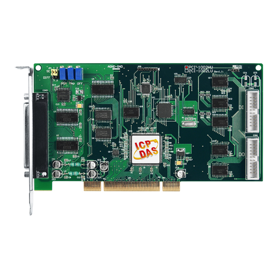
Page 13: Hardware Configuration
2.1 Board Layout PCI-1002LU/HU Board Layout: CON3 CON1 CON2 Figure 2-1: PCI-1002 board layout. CON1: 16-channel D/O CON2: 16-channel D/I CON3: 32 single-ended or 16 differential analog input channels JP1: Analog input type selection PCI-1002 Series User Manual (Ver.2.8, Oct. 2011, PMH-015-28) - Page 14 Figure 2-2: PEX-1002 board layout. CON1: 16-channel D/O CON2: 16-channel D/I CON3: 32 single-ended or 16 differential analog input channels SW1: Card ID function. JP1: Analog input type selection JP2: Pull-high/pull-low jumper for D/I PCI-1002 Series User Manual (Ver.2.8, Oct. 2011, PMH-015-28)
-
Page 15: Jumper Settings
2.2 Jumper Settings The PCI-1002 series has only one jumper. JP1 is used to select the analog input type. For single-ended inputs, users should connected Pins 1-3 and Pins 2-4. For differential inputs, Pins 3-5 and Pins 4-6 should be connected. -
Page 16: A/D Calibration
Step 6: Adjust VR2 until channel 1 = 800 or 801 Step 7: Adjust VR3 until channel 2 = 000 or 001 Step 8: Repeat Step 4, Step 5 and Step 6 until all are OK. PCI-1002 Series User Manual (Ver.2.8, Oct. 2011, PMH-015-28) -
Page 17: Card Id Switch
The default Card ID is 0x0. For detail SW1 Card ID settings, please refer to Table 2.1. (Default Settings) Table 2.1 (*) Default Settings; OFF 1; ON Card ID (Hex) (*) 0x0 ※ Card ID Switch for PEX-1002L/H only PCI-1002 Series User Manual (Ver.2.8, Oct. 2011, PMH-015-28) -
Page 18: System Block
8254 Timer A/D Buffer Data Interrupt Trigger PCI/PEX Converter controller Logic Interface Controller Dispatch Multiplexers controller , Gain Amp. NVRA Scale Adj. External Trigger PCI/PEX Figure 2-2: PCI-1002 series System Function Block. PCI-1002 Series User Manual (Ver.2.8, Oct. 2011, PMH-015-28) -
Page 19: Daughter Boards
The DB-8225 provides an on-board CJC (Cold Junction Compensation) circuit for thermocouple measurement and a terminal block for easy signal connection and measurement. The CJC is connected to A/D channel_0. The PCI-1002 series can connect CON3 directly to DB-8225 through a 37-pin D-sub connector. Refer to “DB-8225 User Manual"... -
Page 20: Db-16P Isolated Input Board
Opto-Isolated PCI-1002 (H/L) 20-Pin cable DB-16P PCI-1002 (H/L) AC or DC Signal 0V to 24V PCI-1002 Series User Manual (Ver.2.8, Oct. 2011, PMH-015-28) -
Page 21: Db-16R Relay Board
Form C Relay Normally Closed Com. 20-Pin cable PCI-1002 (H/L) Series DB-16R Note: Channel: 16 Form C Relay Relay: Switching up to 0.5 A at 110 V or 1 A at 24 V PCI-1002 Series User Manual (Ver.2.8, Oct. 2011, PMH-015-28) -
Page 22: Analog Input Signal Connections
2.7 Analog Input Signal Connections The PCI-1002 series can measure single-ended or differential-type analog input signal. Some analog signals can be measured in both modes. However, some analog signals only can be measured in one or the other. The user must decide which mode is suitable for measurement. - Page 23 A/D CH 0 LO A.GND 1 A/D CH n HI Es n A/D CHn LO A.GND n Figure 2-3. Wrong way A/D CH0HI A/D CH0LO GND1 AGND A/D CHnHI A/D CHnLO GNDn AGND PCI-1002 Series User Manual (Ver.2.8, Oct. 2011, PMH-015-28)
- Page 24 Do not join LO to A.GND at the computer Note: If the input signal is not thermocouple, the user should use an oscilloscope to measure common mode voltage of Vin before connecting to PCI-1002 series. Don’t use a voltage meter or multimeter.
- Page 25 Signal Shielding Signal shielding connections in Figure 2-3 to Figure 2-6 are all the same Use a single-point connection to frame ground (not A.GND or D.GND) PCI-1002 series A.GND D.GND Frame Ground PCI-1002 Series User Manual (Ver.2.8, Oct. 2011, PMH-015-28)
-
Page 26: Pin Assignments
Digital input 10 12 Digital input 11 Digital input 12 14 Digital input 13 +12V Digital input 14 16 Digital input 15 PCB ground PCB ground PCB +5 V PCB +12 V PCI-1002 Series User Manual (Ver.2.8, Oct. 2011, PMH-015-28) - Page 27 1. Once differential analog input is selected (JP1 3-5, 4-6), Pins 1-16 will be assign as the positive inputs while Pins 20-35 will act as the negative inputs of the channel. 2. ‘ N.C. ’ is short for “Not Connected”. PCI-1002 Series User Manual (Ver.2.8, Oct. 2011, PMH-015-28)
-
Page 28: Software Installation
3. Software Installation The PCI-1002 series can be used in DOS and Windows 98/NT/2K and 32-bit/64- bit Windows XP/2003/Vista/7. The recommended installation procedure for windows is given in Sec. 3.1 ~ 3.3. Or refer to Quick Start Guide (CD:\NAPDOS\PCI\PCI-1002\ Manual\QuickStart\). -
Page 29: Pnp Driver Installation
1002/manual/ 3.2 PnP Driver Installation Power off the computer and install the PCI-1002 series card. Turn on the computer and Windows 98/ME/2K and 32-bit/64-bit Windows XP/2003/Vista/7 should automatically defect the new PCI device(s) and then ask for the location of the driver files for the hardware. -
Page 30: Confirm The Successful Installation
3.3 Confirm the Successful Installation Make sure the PCI-1002 series cards installed are correct on the computer as follows: Step 1: Select “Start” “Control Panel” and then double click the “System” icon on Windows. Step 2: Click the “Hardware” tab and then click the “Device Manager” button. -
Page 31: I/O Register Address
We provide the following necessary functions: 1. P1002_DriverInit(&wBoard) This function can detect how many PCI-1002 series cards are in the system. The function is implemented based on the PCI Plug & Play mechanism-1. It will find all PCI-1002 series cards installed in this system & save all their resources in the library. - Page 32 /* control the D/O states of card_1 */ wDiValue=inpw(wBase+0x20); /* read the D/I states of card_1 */ wPLX=wConfigSpace[2][2]; /* get PCI-interface base address of card-2 */ _outpd(wPLX+0x4c,0x41); /* channel_1, interrupt active_Low … … … _outpd(wPLX+0x4c,0); /* disable all interrupt PCI-1002 Series User Manual (Ver.2.8, Oct. 2011, PMH-015-28)
-
Page 33: The I/O Address Map
8/16/32 bits register General control register 8/16/32 bits A/D software trigger 8/16/32 bits Clear Interrupt 8/16/32 bits Digital output register 16/32 bits Digital input register 16/32 bits A/D data register 16/32 bits PCI-1002 Series User Manual (Ver.2.8, Oct. 2011, PMH-015-28) -
Page 34: Section 1
IRQ at the same time. You must use Bit-2 to find out if this IRQ was generated from your PCI- 1002 series!!! 3. For more information about the PCI interrupt control, refers to the PLX-9050 user reference manual. PCI-1002 Series User Manual (Ver.2.8, Oct. 2011, PMH-015-28) - Page 35 Analog input channel A/D data Bit 15-12: The channel number of analog input. Only the lower 4 bits of the channel number are shown in this register. Bit 11-0: The A/D data. PCI-1002 Series User Manual (Ver.2.8, Oct. 2011, PMH-015-28)
- Page 36 110 K) via this method, a reasonable delay time should be left between the two triggers. Delay time Software trigger 8 μs Busy Conversion Time Figure 4-1: Software trigger delay time. PCI-1002 Series User Manual (Ver.2.8, Oct. 2011, PMH-015-28)
- Page 37 [1 1] Gain For PCI-1002H/HU and PEX-1002H: [Bit1, Bit 0] [0 0] [0 1] [1 0] [1 1] Gain 1000 These registers are set to 0 after powered-on or hardware reset signals. PCI-1002 Series User Manual (Ver.2.8, Oct. 2011, PMH-015-28)
- Page 38 [ 1, 0, 0 ] Interrupt after 8254 timer 1 falls. Others No interrupt source, Disable all interrupts. Note: Bit 2-4 of general control register is set to 0 after hardware reset. PCI-1002 Series User Manual (Ver.2.8, Oct. 2011, PMH-015-28)
- Page 39 8254 timer 1 will automatically turn off until it receives a falling external trigger signal. Any change to the trigger mode selection will turn off the post-trigger mode. The A/D trigger is set to 0 after either power-on or hardware reset. PCI-1002 Series User Manual (Ver.2.8, Oct. 2011, PMH-015-28)
-
Page 40: Function Operations
5. Function Operations 5.1 Digital I/O The PCI-1002 series provide 16 digital input channels and 16 digital output channels. All levels are TTL compatible. The connection diagram and block diagram are given below: BaseAddr+20h read signal. DI port Local Data Bus D0 ... -
Page 41: The 8254 Timer
5.2 The 8254 Timer The PCI-1002 series provide 3 independent, 16-bit timer/counters. Each timer has different functions. Timer 0 is uses Pacer 0. Timer 1 is uses Pacer 1. Timer 2 is uses a machine independent timer. The block diagram is given as... - Page 42 Recover time 100ns Note: The PCI-1002 series is designed only as a time sensitive trigger (trigger depends only on receiving a falling edge external trigger signal). For a level sensitive external trigger (trigger depends only on the level of the input signals),...
-
Page 43: A/D Conversion
3 Trigger logic: Software, Pacer or External trigger. 2 Transfer logic: Polling or Interrupt. Here’s the block diagram: 16/8 to 1 Gain 12 bits Multi- Control Buffer Memory plexer BASE+30h BASE+10h BASE+14h Trigger Logic BASE+1Ch Software Trigger PCI-1002 PCI-1002 Series User Manual (Ver.2.8, Oct. 2011, PMH-015-28) - Page 44 The gain control module’s output feeds into the A/D converter. The A/D converter needs a trigger signal to start an A/D conversion cycle. The PCI- 1002 series supports three trigger modes: software, pacer, and external trigger. PCI-1002 Series User Manual (Ver.2.8, Oct. 2011, PMH-015-28)
-
Page 45: A/D Conversion Trigger Modes
This mode can be used with either a pacer trigger or external. A hardware interrupt signal is sent to the PC when an A/D conversion is completed. If using interrupt transfer, it is recommended to use PCI-1002 software driver. PCI-1002 Series User Manual (Ver.2.8, Oct. 2011, PMH-015-28) -
Page 46: Software Triggers And Polling Techniques
/* mode_0, counter_2 */ outp(wBaseAddr+2*4,l); /* counter_2 low byte first */ outp(wBaseAddr+2*4,h); /* counter_2 high byte ,0x07D0=2000 */ outp(wBaseAddr+3*4,0x80); /* latch counter_2 */ l=inp(wBaseAddr+2*4); /* delay starting two CLKs */ h=inp(wBaseAddr+2*4); PCI-1002 Series User Manual (Ver.2.8, Oct. 2011, PMH-015-28) - Page 47 Threr are %d PCI-1002 Cards in this PC",wBoards); if ( wBoards==0 ) putch(0x07); putch(0x07); putch(0x07); printf("(1) There are no PCI-1002 card in this PC !!!\n"); exit(0); printf("\n(2) Show the Configuration Space of all PCI-1002:"); PCI-1002 Series User Manual (Ver.2.8, Oct. 2011, PMH-015-28)
- Page 48 // AdPolling have to disable timer 0 AdPolling(0,0,23); // channel=0, gain=+/-10, delay=23us for(i=0;i<10;i++) outp(wBaseAddr+0x1c,01); // A/D software trigger while(1) if( ((inpw(wBaseAddr+0x10))&0x01)==1) // check if A/D ready? break; wAdData=((inpw(wBaseAddr+0x30))&0x0fff); printf("\nRang:+/-10V, Counter %d ,ADC channel 0 value: 0x%xH",i,wAdData); P1002_DriverClose(); PCI-1002 Series User Manual (Ver.2.8, Oct. 2011, PMH-015-28)
-
Page 49: Software And Demo Program
Declaration files DIO demo For Visual C Interrupt demo P100x.H Header files Pacer demo P100x.LIB Linkage library for VC6 Polling demo VB.NET2005 For VB.NET2005 P100x.vb Declaration files CSharp2005 For C#.NET2005 P100x.cs Declaration files PCI-1002 Series User Manual (Ver.2.8, Oct. 2011, PMH-015-28) -
Page 50: Demo Programs For Dos
DEMO2: Digital output and Digital input test by itself. DEMO3: ADC Polling for channel 0. DEMO4: ADC Polling for channel 0,1,2,3 using different gains-1,2,4 or 8. DEMO5: ADC Pacer trigger. DEMO6: AD Calibration. DEMO7: Find card number. PCI-1002 Series User Manual (Ver.2.8, Oct. 2011, PMH-015-28) -
Page 51: Diagnostic Program
There will be a PCI device with vendor_ID=1234, device_ID=1002 (PCI- 1002 series) If the Plug & Play ROM-BIOS detects the PCI-1002 series card during the power- on time, the software driver of DOS, and Windows 95/NT/2000/XP will function well later. If the Plug & Play ROM-BIOS can’t find the PCI-1002 series, all software drivers will not function. -
Page 52: Dio Test
Step 6: Apply -10V to channel 2. Step 7: Run DEMO6.EXE. Step 8: Check channel 0 = fff or ffe? Step 9: Check channel 1 = 800 or 801? Step 10: Check channel 2 = 000 or 001? PCI-1002 Series User Manual (Ver.2.8, Oct. 2011, PMH-015-28) -
Page 53: Pio_Piso.exe For Windows
List all PIO/PISO cards installed in the PC List the resources allocated to each PIO/PISO card List the Ven_ID and Dev_ID details for identification of specific PIO/PISO cards. (Refer to Sec. 4.1 for more information) PCI-1002 Series User Manual (Ver.2.8, Oct. 2011, PMH-015-28)
Need help?
Do you have a question about the PCI-1002 Series and is the answer not in the manual?
Questions and answers