Table of Contents
Advertisement
Quick Links
VXC-1x8U/PCIe-S1x8 Series
User Manual
S
e
r
i
a
l
C
o
m
m
u
n
i
c
a
t
i
o
n
B
o
a
S
e
r
i
a
l
C
o
m
m
u
n
i
c
a
t
i
o
n
B
o
a
S
e
r
i
a
l
C
o
m
m
u
n
i
c
a
t
i
o
n
B
o
a
W
ARRANTY
All products manufactured by ICP DAS are warranted
against defective materials for a period of one year from
the date of delivery to the original purchaser.
W
ARNING
ICP DAS assumes no liability for damages consequent to
the use of this product. ICP DAS reserves the right to
change this manual at any time without notice. The
information furnished by ICP DAS is believed to be
accurate and reliable. However, no responsibility is
assumed by ICP DAS for its use, nor for any infringements
of patents or other rights of third parties resulting from its
use.
C
OPYRIGHT
Copyright © 2015 by ICP DAS. All rights are reserved.
T
RADEMARKS
Names are used for identification purposes only and may
be registered trademarks of their respective companies.
C
U
ONTACT
S
If you have any questions, please feel free to contact us
at:
Email: service@icpdas.com, service.icpdas@gmail.com
We guarantee to give you response within 2 working days.
r
d
w
i
t
h
8
R
S
-
2
3
2
/
4
2
2
/
4
8
5
P
r
d
w
i
t
h
8
R
S
-
2
3
2
/
4
2
2
/
4
8
5
P
r
d
w
i
t
h
8
R
S
-
2
3
2
/
4
2
2
/
4
8
5
P
o
r
t
s
V
e
r
s
i
o
n
1
.
1
.
o
r
t
s
V
e
r
s
i
o
n
1
.
1
.
o
r
t
s
V
e
r
s
i
o
n
1
.
1
.
S
UPPORT
This manual relates to the following cards:
VXC-118U, VXC-148U
PCIe-S118, PCIe-S148
3
,
J
a
n
.
2
0
1
5
3
,
J
a
n
.
2
0
1
5
3
,
J
a
n
.
2
0
1
5
Advertisement
Table of Contents

Related Manuals for ICP DAS USA VXC-1 8U Series


Summary of Contents for ICP DAS USA VXC-1 8U Series
- Page 1 VXC-1x8U/PCIe-S1x8 Series User Manual UPPORT ARRANTY This manual relates to the following cards: All products manufactured by ICP DAS are warranted against defective materials for a period of one year from VXC-118U, VXC-148U the date of delivery to the original purchaser. PCIe-S118, PCIe-S148 ARNING ICP DAS assumes no liability for damages consequent to...
-
Page 2: Table Of Contents
Serial Communication Board with 8 RS-232/422/485 Ports Table of Contents PACKING LIST ..................................3 MORE INFORMATION ................................3 INTRODUCTION ................................ 4 .............................. 5 EATURES ............................7 PECIFICATIONS 1.2.1 VXC-118U/PCIe-S1x8 ............................. 7 1.2.2 VXC-148U/PCIe-S148 ............................ 8 ............................. 9 PTIONS HARDWARE CONFIGURATION ..........................10 ............................. -
Page 3: Packing List
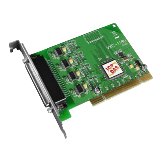
Serial Communication Board with 8 RS-232/422/485 Ports Packing List The shipping package includes the following items: Note: One VXC-1x8U or PCIe-S1x8 If any of these items are missing Series Card or damaged, please contact the local distributor for more information. Save the shipping One Quick Start Guide Quick Start materials and cartons in case... -
Page 4: Introduction
Serial Communication Board with 8 RS-232/422/485 Ports 1. Introduction The VXC-1x8U and PCIe-S1x8 multiport series card is the foremost choice for PC-based communication solutions, ensuring smooth communication in both time-critical applications and industrial fields. Installing a multiport card increases the number of serial ports available on the PC, meaning that it is much easier to integrate a PC with a large number of external devices, such as PLCs, meters, controllers, laboratory instruments, modems, card readers, serial printers, RFID readers, bar code readers, and sensors, etc. -
Page 5: Features
Serial Communication Board with 8 RS-232/422/485 Ports 1.1 Features Universal PCI (3.3 V/5 V) for VXC-1x8U Series Card The Universal PCI card works with both newer 3.3 V PCI bus that is widely-used in servers, and the traditional 5 V PCI bus. The Universal PCI interface will be the standard for every card developed by ICP DAS in the near future. - Page 6 Serial Communication Board with 8 RS-232/422/485 Ports Self-Tuner The VXC-148U/PCIe-S148 card is equipped with an internal “Self-Tuner” chip that is used to automatically control the direction of the transmission and receiving of signals on the RS-485 ports. Without the help inclusion of the Self-Tuner, the RS-485 transmitter would need to be manually enabled before transmitting, and then disabled once the transmission is complete.
-
Page 7: Specifications
Serial Communication Board with 8 RS-232/422/485 Ports 1.2 Specifications 1.2.1 VXC-118U/PCIe-S1x8 Models PCIe-S118 VXC-118U Communication Port COM1 - COM8 RS-232 (TxD, RxD, RTS, CTS, DTR, DSR, DCD, GND) UART 16c950 compatible Baud Rate 2400 – 921600 bps 50 - 115200 bps Data Bits 5, 6, 7, 8 Stop Bits... -
Page 8: Vxc-148U/Pcie-S148
Serial Communication Board with 8 RS-232/422/485 Ports VXC-148U/PCIe-S148 1.2.2 Models PCIe-S148 VXC-148U Communication Port RS-422/485 The RS-422 and RS-485 Cannot be used simultaneously. RS-422 RS-422 (TxD+, TxD-, RxD+, RxD-, GND) COM1 - 2-Wire RS-485 (Data+, Data-, GND) COM8 RS-485 Bias Resistor Yes, 1 KΩ Nodes 256 (max.) UART... -
Page 9: Options
Serial Communication Board with 8 RS-232/422/485 Ports 1.3 Options Item & Description VXC-118U VXC-148U PCIe-S118 PCIe-S148 CA-9-6210 DB-62 Male(D-sub) to 8-Port DB-9 Male(D-sub) Cable 1 m (180 º) CA-PC09F 9-pin Female D-sub Connector with ... -
Page 10: Hardware Configuration
Serial Communication Board with 8 RS-232/422/485 Ports 2. Hardware Configuration 2.1 Board Layout 2.1.1 VXC-118U/VXC-148U For VXC-148U Only Item Description CON1 RS-232 or RS-422/RS-485 Signal. For more detailed information regarding the pin assignments for the VXC-1x8U series card, refer to Section 2.3 Pin Assignments. -
Page 11: Pcie-S118/Pcie-S148
Serial Communication Board with 8 RS-232/422/485 Ports 2.1.2 PCIe-S118/PCIe-S148 For PCIe-S148 Only Item Description CON1 RS-232 or RS-422/RS-485 Signal. For more detailed information regarding the pin assignments for the PCIe-S1x8 series card, refer to Section 2.3 Pin Assignments. The PCIe-S148 supports pull-high/low jumpers allow the Port1/2/3/4/5/6/7/8 can be selected to either pull-high or pull-low via placement of the JP1/2/3/4/5/6/7/8 jumpers. -
Page 12: Wiring Notes For Rs-232/422/485
Serial Communication Board with 8 RS-232/422/485 Ports 2.2 Wiring Notes for RS-232/422/485 2.2.1 RS-232 Wiring Note: FGND is the frame ground that is soldered to the metal shield on the DB-9 cable. 2.2.2 RS-485 Wiring Copyright © 2015 ICP DAS CO., Ltd. All Rights Reserved. - 12 -... -
Page 13: Rs-422 Wiring
Serial Communication Board with 8 RS-232/422/485 Ports 2.2.3 RS-422 Wiring Note: 1. Usually, you have to connect all signal grounds of RS-422/485 devices together to reduce common-mode voltage between devices. 2. Twisted-pair cable must be used for the DATA+/- wires. 3. -
Page 14: Pin Assignments
Serial Communication Board with 8 RS-232/422/485 Ports Pin Assignments 2.3.1 VXC-118U/PCIe-S118 Copyright © 2015 ICP DAS CO., Ltd. All Rights Reserved. - 14 -... -
Page 15: Vxc-148U/Pcie-S148
Serial Communication Board with 8 RS-232/422/485 Ports 2.3.2 VXC-148U/PCIe-S148 Copyright © 2015 ICP DAS CO., Ltd. All Rights Reserved. - 15 -... -
Page 16: Hardware Installation
Serial Communication Board with 8 RS-232/422/485 Ports 3. Hardware Installation Note: As certain operating systems, such as Windows XP may require the computer to be restarted after a new driver is installed, it is recommended that the driver is installed first, which will reduce the installation time. - Page 17 Serial Communication Board with 8 RS-232/422/485 Ports Step 3: Remove the cover from the computer. Step 4: Select an empty PCI/PCI Express slot. Step 5: Unscrew and remove the PCI/PCI Express slot cover from the computer case. Copyright © 2015 ICP DAS CO., Ltd. All Rights Reserved. - 17 -...
- Page 18 Serial Communication Board with 8 RS-232/422/485 Ports Step 6: Remove the connector cover from the VXC- 1x8U/PCIe-S1x8 series card. Step 7: Carefully insert the VXC-1x8U/PCIe-S1x8 series card into the PCI/PCI Express slot by gently pushing down on both sides of the card until it slides into the PCI connector. Step 8: Confirm that the card is correctly inserted in the motherboard, and then secure the VXC-1x8U/PCIe-S1x8 series card in place using the retaining screw that was...
- Page 19 Serial Communication Board with 8 RS-232/422/485 Ports Step 9: Replace the covers on the computer. Step 10: Re-attach any cables, insert the power cord and then switch on the power to the computer. Once the computer reboots, follow the onscreen messages to complete the Plug and Play installation process.
-
Page 20: Software Installation
Serial Communication Board with 8 RS-232/422/485 Ports 4. Software Installation The VXC-1x8U/PCIe-S1x8 series card can be used with both 32 and 64-bit Windows XP/2003/Vista/7/8 systems, and also supports Plug and Play (PnP) functions for easy installation. This chapter provides detailed description of how to install the drivers for the VXC-1x8U/PCIe-S1x8 series card. -
Page 21: Installing Vxc-1 X 8U Series Driver
Serial Communication Board with 8 RS-232/422/485 Ports Installing VXC-1x8U Series Driver Follow the process described below to set up the software for the VXC-118U and VXC-148U card: Step 1: Double-click the “VXC_1x8_Win_Setup_xxxx” application to install the driver. Step 2: When the Setup Wizard screen is displayed, click the “Next>”... - Page 22 Serial Communication Board with 8 RS-232/422/485 Ports Step 4: The Setup Wizard will then display a warning message asking you to confirm that you wish to install the device software. Refer to the figures below for details. For Windows XP/2003 (32-/64-bit) In the “Hardware Installation”...
- Page 23 Serial Communication Board with 8 RS-232/422/485 Ports Step 5: Once the driver has been installed, the Setup Wizard will be displayed to advise that the computer must be restarted in order to complete the installation. Select the “No, I will restart the computer later”...
-
Page 24: Installing Pcie-S1X8 Series Driver
Serial Communication Board with 8 RS-232/422/485 Ports Installing PCIe-S1x8 Series Driver Follow the process described below to set up the software for the PCIe-S118 and PCIe-S148 card: Step 1: Double-click the “PCIe_S1x8_Win_Setup_xxxx” application to install the driver. Step 2: When the Setup Wizard screen is displayed, click the “Next>”... - Page 25 Serial Communication Board with 8 RS-232/422/485 Ports Step 4: In the installation process, the Command Prompt windows will be displayed, don't care. Note: Please do not close this Command Prompt window in installation process. Step 5: Once the driver has been installed, the Setup Wizard will be displayed to advice that the computer must be restarted in order to complete the installation.
-
Page 26: Pnp Driver Installation
Serial Communication Board with 8 RS-232/422/485 Ports 4.4 PnP Driver Installation Step 1: Correctly shut down and power off your computer and disconnect the power supply, and then install the VXC-1x8U/PCIe-S1x8 series card into the computer. For detailed information regarding installation of the VXC-1x8U/PCIe-S1x8 series card, refer to Chapter 3 Hardware Installation. - Page 27 Serial Communication Board with 8 RS-232/422/485 Ports Step 4: The “Found new Hardware Wizard” will be displayed to advice that the software installation has been completed. Click the “Finish” button to exit the Wizard. Step 5: If the “Found New Hardware Wizard” dialog box is displayed again, repeat Steps 3 and to complete the installation for all COM ports.
-
Page 28: Verifying The Installation
Serial Communication Board with 8 RS-232/422/485 Ports 4.5 Verifying the Installation To verify that the driver was correctly installed, use the Windows Device Manager to view and update the device drivers installed on the computer, and to ensure that the hardware is operating correctly. - Page 29 Serial Communication Board with 8 RS-232/422/485 Ports Windows Vista/7 Step 1: Click the “Start” button. Step 2: In the Search field, type Device Manager and then press Enter. Note that Administrator privileges are required for this operation. If you are prompted for an administrator password or confirmation, enter the password or provide confirmation by clicking the “Yes”...
-
Page 30: Check The Configuration Of The Com Port
Serial Communication Board with 8 RS-232/422/485 Ports 4.5.2 Check the Configuration of the COM Port Step 3: Verify that the COM Ports for the VXC-1x8/PCIe-S1x8 series card listed correctly. Installation successful Note: Depending on the operating system, the COM port mapping may be applied automatically. -
Page 31: Manual Com Port Configuration
Serial Communication Board with 8 RS-232/422/485 Ports 4.6 Manual COM Port Configuration The VXC-1x8U and PCIe-S1x8 series card supports 8 RS-232 or RS-422/485 serial ports. Depending on the operating system, COM port mapping may be applied automatically during the hardware and software installation. - Page 32 Serial Communication Board with 8 RS-232/422/485 Ports Step 4: Once the remapping has been completed, a window will be displayed indicating the new COM Port numbers. Copyright © 2015 ICP DAS CO., Ltd. All Rights Reserved. - 32 -...
-
Page 33: Pcie-S118/Pcie-S148
Serial Communication Board with 8 RS-232/422/485 Ports 4.6.2 PCIe-S118/PCIe-S148 The COM port mapping can be adjusted depending on the requirements of you. For detailed configuration steps, please refer to the following: Step 1: Open Windows Device Manager. Refer to Section 4.5.1 for more detailed information. - Page 34 Serial Communication Board with 8 RS-232/422/485 Ports Step 4: Select the “Port Settings” item in the “Communications Port (COM n) Properties” dialog box. Step 5: Click the “Advanced…” button to open the “Advanced Settings for COM n” dialog box. Step 6: In “Advanced Settings for COM n” dialog box, select the appropriate COM Port number from the “COM Port Number:”...
- Page 35 Serial Communication Board with 8 RS-232/422/485 Ports Step 8: Restart your computer to complete the configuration. Step 9: Confirm the new COM Ports is correctly displayed. Copyright © 2015 ICP DAS CO., Ltd. All Rights Reserved. - 35 -...
-
Page 36: Uninstalling The Device Driver
Serial Communication Board with 8 RS-232/422/485 Ports 4.7 Uninstalling the Device Driver The ICP DAS VXC-1x8U/PCIe-S1x8 series card driver includes a utility that allows the software from your computer. To uninstall the software, follow the procedure described below: Step 1: Open the driver installation folder, for example C:\ICPDAS\VXC-1x8 (or PCIe-S1x8), and then double click the unins000.exe... -
Page 37: Testing The Multiport Series Card
Serial Communication Board with 8 RS-232/422/485 Ports Multiport 5. Testing the Series Card This chapter provides detailed information regarding the “self-test” process, which enables the user to confirm whether or not the VXC-1x8U/PCIe-S1x8 series card is operating correctly. Before performing the “self-test”, the hardware and driver installation must be completed. For detailed information regarding hardware and driver installation, refer to Chapter 3 Hardware Installation Chapter 4 Software... - Page 38 Serial Communication Board with 8 RS-232/422/485 Ports VXC-118U/PCIe-S118 Card (RS-232 Wiring): Pin Assignment Pin No. Pin No. Pin Assignment TxD0 RxD1 RxD0 TxD1 Step 2: Perform the “self-test” by shorting the RxD, TxD and GND pins of both Port0 and Port1.
-
Page 39: Execute The Test Program
Serial Communication Board with 8 RS-232/422/485 Ports 5.2 Execute the Test Program Step 1: Execute the “Test2COM.exe” application, which can be found on the companion CD at: CD\Napdos\multiport\utility Or download it from: http://ftp.icpdas.com/pub/cd/iocard/pci/napdos/multiport/utility/ Step 2: Set the appropriate COM Ports, Baud Rate and Data Format information to the values shown in the image below. - Page 40 Serial Communication Board with 8 RS-232/422/485 Ports Notes: 1. Depending on the operating system, COM port mapping may be applied automatically. You should first confirm the number of the COM Port for VXC-1x8U/PCIe-S1x8 series card through Device Manager (see Section 4.5 Verifying the Installation) and then test this COM Port using the Test2COM.exe application.
Need help?
Do you have a question about the VXC-1 8U Series and is the answer not in the manual?
Questions and answers