Danfoss VLT DriveMotor FCP 106 Operating Instructions Manual
Hide thumbs
Also See for VLT DriveMotor FCP 106:
- Programming manual (148 pages) ,
- Design manual (82 pages) ,
- Operating instructions manual (54 pages)
Table of Contents
Advertisement
Quick Links
Download this manual
See also:
Programming Manual
Advertisement
Table of Contents

Related Manuals for Danfoss VLT DriveMotor FCP 106


Summary of Contents for Danfoss VLT DriveMotor FCP 106
- Page 1 MAKING MODERN LIVING POSSIBLE Operating Instructions VLT® DriveMotor FCP 106/FCM 106 vlt-drives.danfoss.com...
-
Page 3: Table Of Contents
4.1 Safety Instructions 4.2 IT Mains 4.3 EMC-compliant Installation 4.4 Cable Requirements 4.5 Grounding 4.6 Motor Connection 4.6.1 Connect FCP 106 to Motor 4.6.2 Thermistor Input from Motor 4.7 AC Mains Connection MG03L302 Danfoss A/S © 11/2015 All rights reserved. - Page 4 7.4 Protection and Features 7.5 Ambient Conditions 7.6 Cable Specifications 7.7 Control Input/Output and Control Data 7.8 Connection Tightening Torques 7.9 FCM 106 Motor Specifications 7.10 Fuse and Circuit Breaker Specifications 8 Appendix Danfoss A/S © 11/2015 All rights reserved. MG03L302...
-
Page 5: Control Terminals And Relays
Contents Operating Instructions 8.1 Abbreviations and Conventions 8.2 Parameter Menu Structure Index MG03L302 Danfoss A/S © 11/2015 All rights reserved. -
Page 6: Introduction
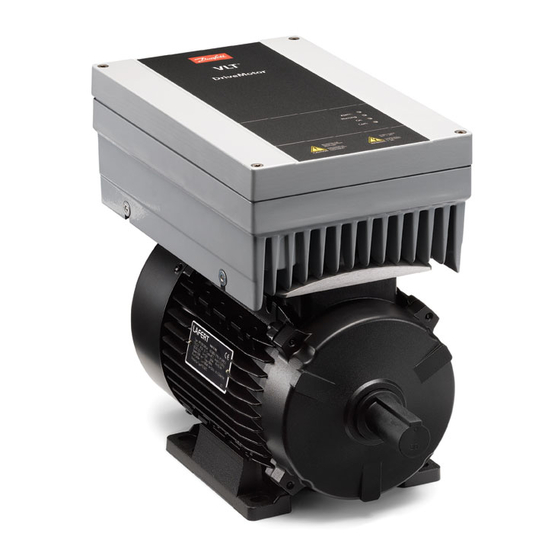
Order the wall mount kit or adapter plate and power crimp terminals separately. Illustration 1.1 FCP 106 Illustration 1.2 FCM 106 Danfoss A/S © 11/2015 All rights reserved. MG03L302... -
Page 7: Additional Resources
-based PC environment. are non-compliant with specified operating conditions and • ® Danfoss VLT Energy Box software, for energy environments. Ensure compliance with the conditions calculation in HVAC applications. specified in chapter 7 Specifications. MG03L302 Danfoss A/S © 11/2015 All rights reserved. -
Page 8: Electrical Overview
24 V (NPN) RS485 RS485 (N RS485) 69 0 V (PNP) Interface 29 (DIGI IN) 24 V (NPN) (P RS485) 68 0 V (PNP) (Com RS485) 61 (PNP)-Source PROFIBUS (NPN)-Sink Illustration 1.3 Electrical Overview Danfoss A/S © 11/2015 All rights reserved. MG03L302... -
Page 9: Approvals
1.5 Disposal Instruction Equipment containing electrical components must not be disposed of together with domestic waste. It must be separately collected with electrical and electronic waste according to local and currently valid legislation. MG03L302 Danfoss A/S © 11/2015 All rights reserved. -
Page 10: Safety
Only qualified personnel are permitted to in Table 2.1. perform installation, start-up, and maintenance. • Before performing any service or repair work, use an appropriate voltage measuring device to make sure that the capacitors are fully discharged. Danfoss A/S © 11/2015 All rights reserved. MG03L302... - Page 11 RCD of Type B (time delayed) on the supply side of this product. • Protective earthing (PE) of the frequency converter and the use of RCDs must always follow national and local regulations. MG03L302 Danfoss A/S © 11/2015 All rights reserved.
- Page 12 Do not ground one frequency converter to another in a daisy chain fashion. • Keep the ground wire connections as short as possible. • Use high-strand wire to reduce electrical noise. • Follow the motor manufacturer’s wiring requirements. Danfoss A/S © 11/2015 All rights reserved. MG03L302...
-
Page 13: Mechanical Installation
Illustration 3.1 FCP 106 Nameplate (Example) 2 pieces for thermistor (optional). 1 piece for grounding terminal. • 2 guiding pins (optional). 1) Example of format: Serial number ‘xxxxx253’ indicates manufacture in week 25, year 2013. MG03L302 Danfoss A/S © 11/2015 All rights reserved. -
Page 14: Lifting
The frequency converter complies with requirements for units mounted on the walls and floors of production premises, as well as in panels bolted to walls or floors. For detailed ambient conditions specifications, refer to chapter 7.5 Ambient Conditions. Danfoss A/S © 11/2015 All rights reserved. MG03L302... -
Page 15: Mounting
See chapter 4.6.1 Connect FCP 106 to Motor. The combined unit is then known as the DriveMotor. Mount the DriveMotor, see chapter 3.3.4 Mount the DriveMotor. Perform the remaining electrical installation, see chapter 4.7.1 Connecting to Mains. MG03L302 Danfoss A/S © 11/2015 All rights reserved. -
Page 16: Prepare Adapter Plate
For adapter plate with pre-drilled holes, no extra holes are required. Pre-drilled holes are specific for FCM 106 motors only. Area 1 Area 2 Illustration 3.3 Adapter Plate, Guide for Drilling Holes Danfoss A/S © 11/2015 All rights reserved. MG03L302... -
Page 17: Mount The Drivemotor
NOTICE Tapping of fittings onto the motor shaft, with a hammer or mallet, causes bearing damage. This damage results in an increase in bearing noise and a significant reduction in bearing life. MG03L302 Danfoss A/S © 11/2015 All rights reserved. -
Page 18: Bearing Life And Lubrication
Permissible radial forces: Load point corresponding to half-shaft extension, 0 axial force assumed. Permissible axial forces: 0 radial force assumed. Permissible loads of simultaneous radial and axial forces can be supplied on request. Danfoss A/S © 11/2015 All rights reserved. MG03L302... - Page 19 6306 2ZC3 1500/3000 6208 2ZC3 6208 2ZC3 6309 2ZC3 6208 2ZC3 1500/3000 – – 1500/3000 – – Table 3.4 Standard Bearing References and Oil Seals for Motors 1) Data available at future release. MG03L302 Danfoss A/S © 11/2015 All rights reserved.
-
Page 20: Electrical Installation
• Power connection wire recommendation: Minimum 75 °C (167 °F) rated copper wire. See chapter 7 Specifications and chapter 7.6 Cable Specifi- cations for recommended wire sizes and types. Danfoss A/S © 11/2015 All rights reserved. MG03L302... -
Page 21: It Mains
In this mode, the internal RFI filter capacitors between RFI switch/screw housing and the mains RFI filter circuit are disabled, to reduce the ground capacity currents. Illustration 4.2 Location of RFI Switch/Screw CAUTION To reinsert, use an M3.5x20 screw only. MG03L302 Danfoss A/S © 11/2015 All rights reserved. -
Page 22: Emc-Compliant Installation
Mains, 3-phase, and reinforced PE Frequency converter Cable insulation (stripped) Minimum 200 mm (7.87 in) clearance between control cable, mains cable, and mains motor cable. Illustration 4.3 EMC-compliant Electrical Installation, FCP 106 Danfoss A/S © 11/2015 All rights reserved. MG03L302... - Page 23 Operating Instructions Control cables DriveMotor Mains, 3-phase, and reinforced PE Minimum 200 mm (7.87 in) clearance between control Cable insulation (stripped) cable and mains cable. Illustration 4.4 EMC-compliant Electrical Installation, FCM 106 MG03L302 Danfoss A/S © 11/2015 All rights reserved.
-
Page 24: Cable Requirements
The FCP 106 is now mounted onto the motor. The or frequency converter. combined unit is known as the DriveMotor. To connect the FCP 106 to the motor, follow the instal- lation steps shown in Table 4.1 and Illustration 4.5. Danfoss A/S © 11/2015 All rights reserved. MG03L302... - Page 25 U, V, W (motor phases) Adapter plate (motor thermistor wires) Motor connector gasket Motor connector Gasket between motor and motor bracket Frequency converter Motor cables Fastening screw Illustration 4.5 Connecting FCP 106 to Motor MG03L302 Danfoss A/S © 11/2015 All rights reserved.
-
Page 26: Thermistor Input From Motor
Connect the mains cable to terminals L1, L2, and L3, and tighten the screws. See Illustration 4.8. Reassemble cover and tighten screws. Illustration 4.7 Remove Front Cover For tightening torques, see chapter 7.8 Connection Tightening Torques. Danfoss A/S © 11/2015 All rights reserved. MG03L302... -
Page 27: Danfoss A/S © 11/2015 All Rights Reserved
Illustration 4.8 Cabling, MH1–MH3 Control terminals Relay terminals UDC+, UDC-, Line (L3, L2, L1) LCP connector ® PROFIBUS DP MCA 101 ® Memory Module MCM 101 Illustration 4.9 Location of Terminals and Relays, MH1 MG03L302 Danfoss A/S © 11/2015 All rights reserved. -
Page 28: Load Sharing
UDC+ and UDC- terminals. Limit the voltage between these terminals to maximum 768 V. NOTICE Increasing voltage beyond the limit decreases life, and Illustration 4.11 Control Terminals may permanently damage the frequency converter. Danfoss A/S © 11/2015 All rights reserved. MG03L302... -
Page 29: Installation Checklist
POTENTIAL HAZARD IN THE EVENT OF INTERNAL FAILURE Risk of personal injury if the frequency converter is not properly closed. • Before applying power, ensure that all safety covers are in place and securely fastened. MG03L302 Danfoss A/S © 11/2015 All rights reserved. -
Page 30: Recommendations For Ul-Listed Prgy Systems
Parameter 14-20 Reset Mode. Parameter 14-21 Automatic Restart Time. Parameter 14-90 Fault Level. Parameter 30-22 Locked Rotor Detection. • Do not exceed the temperature limits stated in the motor data provided by the motor manufacturer. Danfoss A/S © 11/2015 All rights reserved. MG03L302... -
Page 31: Commissioning
D. Operation keys and indicator lights (LEDs). Display settings. Call- Display Parameter Default setting number 0-20 Reference % 0-21 Motor current 0-22 Power [kW] 0-23 Frequency 0-24 kWh counter Table 5.1 Legend to Illustration 5.2 MG03L302 Danfoss A/S © 11/2015 All rights reserved. - Page 32 After use, remove the LCP cable from the frequency alarm text is shown. converter to maintain the ingress protection class of the enclosure. Table 5.4 Legend to Illustration 5.2 Danfoss A/S © 11/2015 All rights reserved. MG03L302...
-
Page 33: Memory Module Mcm 101
Ordering number: 134B0791. Applications. • Chapter 5.4.3 Quick Menu Motor Set-up. • Chapter 5.4.5 Thermistor Set-up. For general instructions on how to change parameter settings, refer to chapter 5.4.4 Changing Parameter Settings. MG03L302 Danfoss A/S © 11/2015 All rights reserved. -
Page 34: Configuration For Open-Loop Applications
DIG IN DIG IN +10 V (OUT) A IN Reference A IN COM IN/OUT 0–10 V A OUT / D OUT A OUT / D OUT Illustration 5.5 Principle Wiring for Open-loop Applications Danfoss A/S © 11/2015 All rights reserved. MG03L302... - Page 35 Perform AMA Auto Motor Adapt OK AMA running AMA Failed Wizard completed ----- Press OK Press OK to accept 0.0 Hz 0.0 kW AMA OK AMA failed Illustration 5.6 Configuration for Open-loop Applications MG03L302 Danfoss A/S © 11/2015 All rights reserved.
-
Page 36: Set-Up Wizard For Closed-Loop Applications
6-21 T54 high Voltage 13.30 0220 20-93 PI Proportional Gain 00.50 6-25 T54 high Feedback 6-25 T54 high Feedback 0050 20-94 PI integral time 0050 0020.00 1-29 Automatic Motor Adaption Illustration 5.7 Closed-loop Set-up Wizard Danfoss A/S © 11/2015 All rights reserved. MG03L302... -
Page 37: Quick Menu Motor Set-Up
4-13 Motor speed high limit 0050 3-41 Ramp 1 ramp-up time 0003 3-42 Ramp1 ramp-down time MotorType = Asynchronous 0003 1-73 Flying Start MotorType = PM Motor Illustration 5.8 Quick Menu Motor Set-up MG03L302 Danfoss A/S © 11/2015 All rights reserved. -
Page 38: Changing Parameter Settings
5.4.5 Thermistor Set-up Set parameter 1-90 Motor Thermal Protection to [1] Thermistor warning or [2] Thermistor trip. For details, refer to ® DriveMotor FCP 106 and FCM 106 Programming Guide. Danfoss A/S © 11/2015 All rights reserved. MG03L302... -
Page 39: Maintenance, Diagnostics And Troubleshooting
Brake chopper fault: The brake transistor is short-circuited, or the brake function is disconnected. If short-circuited, substantial energy is dissipated in the brake resistor. Turn off the frequency converter as a fire precaution. Brake check Brake checked and failure detected. MG03L302 Danfoss A/S © 11/2015 All rights reserved. - Page 40 Option change The temperature sensor on the power card is either too hot or too Pwr. Card Temp cold. Danfoss A/S © 11/2015 All rights reserved. MG03L302...
- Page 41 Fire Mode Fire mode has been activated. Fire Mode Fire mode has suppressed 1 or more warranty voiding alarms. Limits Exceeded Memory module Memory module alarm Table 6.1 Warnings and Alarms MG03L302 Danfoss A/S © 11/2015 All rights reserved.
-
Page 42: Specifications
Table 7.2 Details for Motor Adapter Plate Screws Adapter plate Screw Maximum depth of hole into adapter plate Maximum height of screw above adapter plate Illustration 7.1 Screws to Fasten Motor Adapter Plate Danfoss A/S © 11/2015 All rights reserved. MG03L302... -
Page 43: Fcp 106 Dimensions
276.8 (10.9) 166 (6.5) 187.1 (7.4) 113.2 (4.5) 127.8 (5.0) 5.5–7.5 (7.5–10) 321.7 (12.7) 211 (8.3) 221.1 (8.7) 123.4 (4.9) 138.1 (5.4) Table 7.3 FCP 106 Dimensions 1) Power ratings relate to NO, see chapter 7.2 Electrical Data. MG03L302 Danfoss A/S © 11/2015 All rights reserved. -
Page 44: Fcm 106 Dimensions
347 (13.7) – – – – 314 (12.4) 314 (12.4) 331 (13.0) 331 (13.0) 359 (14.1) 394 (15.5) 394 (15.5) Table 7.4 FCM 106 Dimensions: Foot Mounting - B3 Asynchronous or PM Motor Danfoss A/S © 11/2015 All rights reserved. MG03L302... - Page 45 319 (12.6) 347 (13.7) – – – 314 (12.4) 314 (12.4) 331 (13.1) 359 (14.1) 394 (15.5) Table 7.5 FCM 106 Dimensions: Flange Mounting - B5, B35 for Asynchronous or PM Motor MG03L302 Danfoss A/S © 11/2015 All rights reserved.
- Page 46 302 (11.9) 319 (12.6) 347 (13.7) – – – 314 (12.4) 331 (13) 359 (14.1) 394 (15.5) Table 7.6 FCM 106 Dimensions: Face Mounting - B14, B34 for Asynchronous or PM motor Danfoss A/S © 11/2015 All rights reserved. MG03L302...
-
Page 47: Weight
28 (61.7) 5.5 (7.5) 30 (66) 16 (35.3) 132S 55 (121.3) 112M 53 (116.8) 7.5 (10) 33 (72.8) 112M 26 (57.3) 132M 65 (143.3) 112M 53 (116.8) Table 7.9 Approximate Weight of Motor MG03L302 Danfoss A/S © 11/2015 All rights reserved. -
Page 48: Electrical Data
4) Efficiency measured at nominal current. For energy efficiency class, see chapter 7.5 Ambient Conditions. For part load losses, see www.danfoss.com/vltenergyefficiency. 5) Measured using 4 m screened motor cables at rated load and rated frequency. Danfoss A/S © 11/2015 All rights reserved. MG03L302... - Page 49 4) Efficiency measured at nominal current. For energy efficiency class, see chapter 7.5 Ambient Conditions. For part load losses, see www.danfoss.com/vltenergyefficiency. 5) Measured using 4 m screened motor cables at rated load and rated frequency. MG03L302 Danfoss A/S © 11/2015 All rights reserved.
-
Page 50: Mains Supply
Relative humidity (IEC 60721-3-3; Class 3K4 (non-condensing)) 5–95% during operation Aggressive environment (IEC 60721-3-3) Class 3C3 Test method according to IEC 60068-2-43 H2S (10 days) 40 °C (104 °F) (24-hour average) Ambient temperature Danfoss A/S © 11/2015 All rights reserved. MG03L302... -
Page 51: Cable Specifications
53, 54 Terminal 53 mode Parameter 6-19 Terminal 53 mode: 1=voltage, 0=current Terminal 54 mode Parameter 6-29 Terminal 54 mode: 1=voltage, 0=current Voltage level 0–10 V Input resistance, R Approximately 10 kΩ MG03L302 Danfoss A/S © 11/2015 All rights reserved. - Page 52 Minimum terminal load on 01-03 (NC), 01-02 (NO) 24 V DC 10 mA, 24 V AC 20 01-03/04-06 (NC) (Resistive load) Environment according to EN 60664-1 Overvoltage category III/pollution degree 2 1) IEC 60947 sections 4 and 5. Danfoss A/S © 11/2015 All rights reserved. MG03L302...
-
Page 53: Connection Tightening Torques
), 0–400 Hz (u/f ) Output frequency, PM motor 0–390 Hz (VVC Switching on output Unlimited Ramp times 0.05–3600 s Thermistor input (at motor connector) Fault: >2.9 kΩ, no fault: <800 Ω Input conditions MG03L302 Danfoss A/S © 11/2015 All rights reserved. -
Page 54: Fuse And Circuit Breaker Specifications
Design fuses for protection in a circuit capable of supplying a maximum of 100000 A (symmetrical), 480 V maximum. See Table 7.15 and Table 7.16 for breaking capacity for Danfoss CTI25M circuit breaker at 480 V maximum. - Page 55 0.55 (0.75) 0.75 (1.0) 1.1 (1.5) 1.5 (2.0) 2.2 (3.0) 3.0 (4.0) 4.0 (5.0) 5.5 (7.5) 7.5 (10) Table 7.17 Fuses 1) Power ratings relate to NO, see chapter 7.2 Electrical Data. MG03L302 Danfoss A/S © 11/2015 All rights reserved.
-
Page 56: Appendix
Numbered lists indicate procedures. • Bullet lists indicate other information and description of illustrations. • Italicised text indicates: Cross-reference. Link. Footnote. Parameter name. Parameter group name. Parameter option. • All dimensions are in mm (inch). Danfoss A/S © 11/2015 All rights reserved. MG03L302... - Page 57 Appendix Operating Instructions MG03L302 Danfoss A/S © 11/2015 All rights reserved.
- Page 58 Appendix VLT® DriveMotor FCP 106/FCM 106 Danfoss A/S © 11/2015 All rights reserved. MG03L302...
- Page 59 Cooling clearance................. 27 Current High altitude..................... 9 DC current................... 18 High voltage..................8, 31 DC overvolt..................... 37 Identification..................11 DC undervolt..................37 Indicator light..................30 Derating Autoderating functions..............48 Input power.................... 27 MG03L302 Danfoss A/S © 11/2015 All rights reserved.
- Page 60 Protection and features..............48 Safety....................37 Protection rating................... 54 Manual......................4 Protective extra low voltage............48, 54 see also Document Mechanical installation..............22 see also Installation, mechanical Qualified personnel................8 Memory module................... 54 Danfoss A/S © 11/2015 All rights reserved. MG03L302...
- Page 61 The EMC Directive 2004/108/EC........... 7 Windmilling....................9 The Low Voltage Directive (2006/95/EC)........7 UL 508C....................49 Wire size....................18 Start-up....................29 Storage..................... 12 Switching on the input supply............48 System feedback..................5 MG03L302 Danfoss A/S © 11/2015 All rights reserved.
- Page 62 Danfoss can accept no responsibility for possible errors in catalogues, brochures and other printed material. Danfoss reserves the right to alter its products without notice. This also applies to products already on order provided that such alterations can be made without subsequential changes being necessary in specifications already agreed. All trademarks in this material are property of the respective companies.