Table of Contents
Advertisement
Advertisement
Table of Contents

Related Manuals for Flavel Sophia Simline BF


Summary of Contents for Flavel Sophia Simline BF
- Page 1 Sophia Slimline BALANCED FLUE LOG EFFECT GAS FIRE Installation, Maintenance & User Instructions Hand these instructions to the user Model No’s FSBL**RN is only for use on Natural Gas (G20) at a supply pressure of 20 mbar in G.B. / I.E. ** denotes cosmetic variant...
- Page 2 Information Requirements for Commission Regulation (EU) 2015/1188 Model Identifier FSBL**RN Indirect Heating Functionality Direct Heat Output 4.3kW Indirect Heat Output Not Applicable Fuel NG (G20) NOx Emissions 130mg/kWh Nominal Heat Output 4.3kW Minimum Heat Output (Indicative) 1.3kW Useful Efficiency at Nominal Heat Output 87.2% Useful Efficiency at Minimum Heat Output 50.0%...
-
Page 3: Table Of Contents
CONTENTS PAGE Section 1 Information and Requirements Appliance Information Conditions of Installation Fireplace surround & suitability Flue Terminal Position Shelf position Hearths Section 2 Installation of Fire Unpacking the fire Fireplace opening Preparation of the wall Preparation of the flue hole Installation of the gas supply Preparation of the flue duct Securing the firebox to the opening... -
Page 4: Information And Requirements
SECTION 1 INFORMATION AND REQUIREMENTS APPLIANCE INFORMATION Model FSBL**RN ** denotes cosmetic variant of product Gas Type Main injector (1 off) Size 1.70mm Pilot Type Black Technigas “Polidoro” G27.2 Max. Gross Heat Input : 5.5 kW Min. Gross Heat Input : 2.5 kW 0.511 m 3 /hr Gas Rate :... -
Page 5: Conditions Of Installation
INSTALLATION REQUIREMENTS Efficiency Declaration The efficiency of this appliance has been measured as specified in BS EN 613 : 2001 and the result after conversion to Gross using the appropriate factor from Table 4 of SAP 2009 is 78%. The test data from which it has been calculated has been certified by BSI. -
Page 6: Flue Terminal Position
FLUE TERMINAL POSITION The minimum acceptable dimensions from the flue terminal to obstructions and ventilation openings are shown below and listed in the table It is important that the position of the flue allows the free passage of air across it at all times. The minimum acceptable space from the flue terminal to obstructions and ventilation openings are specified below (figure 2). -
Page 7: Shelf Position
SHELF POSITION This fire must not be fitted below combustible shelf materials. HEARTHS This appliance must only be installed with the Flavel Sophia Slimline hearth panel or an alternative item as dimensionally approved by BFM Europe. SECTION 2 INSTALLATION OF FIRE UNPACKING THE FIRE Carefully lift the fire out of the carton. -
Page 8: Fireplace Opening
FIRE PLACE OPENING 2.2.1 The front opening of the fire place must be between 750 and 840mm wide and between 1025mm and 1050mm high. If the opening exceeds these dimensions then a surround must be constructed from suitable non-combustible material to produce a suitable sized opening. Any surround must be suitably sealed to the fire place to prevent leakage. -
Page 9: Preparation Of The Wall
Fig. 5 Flue Terminal Outer Wall Cavity 154mm 746mm 938mm Including Firebox Flanges 300mm PREPARATION OF THE WALL 2.3.1 The appliance and flue pipes must be installed at right angles to the mounting wall. The appliance itself should be installed vertically against a flat wall. -
Page 10: Preparation Of The Flue Hole
Fig. 6 150mm diameter 870mm PREPARATION OF THE FLUE HOLE 2.4.1 Mark the position of the centre of the flue on the inner wall. 2.4.2 Cut hole for outer flue pipe. There are two possible methods to achieve this, either core drill or via hammer and chisel. 2.4.3 To core drill, proceed as follows :- Drill a pilot hole through the wall, in position as specified in figure 6. -
Page 11: Installation Of The Gas Supply
INSTALLATION OF THE GAS SUPPLY 2.5.1 Before installing the firebox, decide from which side or if a rear connection to the gas supply is required. Plan the pipe run to enter the firebox from the left, right or rear and connect to the inlet elbow. See below :- 2.5.2 If concealed pipe work is required plan the pipe run to enter the fire box... -
Page 12: Preparation Of The Flue Duct
PREPARATION OF THE FLUE DUCT 2.6.1 Place the firebox into the fire opening with fire surround correctly secured in the final position. From the outside of the house measure from the face of the outside wall to the rear panel of the firebox through the flue hole. -
Page 13: Securing The Firebox To The Opening
SECURING OF FIREBOX TO THE OPENING 2.7.1 There is a choice of methods of fixing the firebox that are provided to enable the installer to deal with any type of installation. The preferred method of fixing the appliance is the cable fixing method, which is described in detail in the following section. - Page 14 up to the fireplace. 2.7.8 Thread a tensioning screw over both of the cables and ensure that the tensioning nut is screwed fully up against the hexagon shoulder of the tensioning screw (this provides maximum travel for the tensioning nut). 2.7.9 Fit a screwed nipple on to each of the cables and pull hand tight up against the tensioning screw, then secure each nipple with a...
-
Page 15: Installing The Sophia Surround
INSTALLING THE SOPHIA SURROUND 2.8.1 Unpack the surround from the wooden crate, check all parts are present as per figure 11 overpage and carefully store the components. 2.8.2 The underside of the hearth should be painted with a weak PVA (8 parts water to 1 part PVA). - Page 16 2.8 - Fig. 11 - Sophia Surround Leg Securings Brackets Shelf Securings Brackets Shelf Top Section Shelf Infill Section L/H Leg Top Infill Section Shelf Infill Securing Brackets L/H Infill Section R/H Leg Hearth Panel Bottom Infill Section R/H Infill Section Contents of Sophia Surround :- 1 off Hearth...
-
Page 17: Making The Gas Connection / Pressure Testing
MAKING THE GAS CONNECTION / PRESSURE TESTING THIS APPLIANCE IS INTENDED FOR USE ON A GAS SUPPLY WITH A GOVERNED METER. 2.9.1 The gas connection should be made to the appliance inlet elbow to using 8mm rigid tubing. 2.9.2 Remove the pressure test point screw from the inlet elbow and fit a manometer. -
Page 18: Removal & Refitting Of The Glass Frame
2.11 REMOVING & REFITTING OF THE GLASS FRAME. 2.11.1 Remove the glass panel by firstly removing the lower infill panel, and black trim, then affixing the glass clamp to the glass panel as shown below in figure 13 (Images shown with surround installed, please install firebox before surround). - Page 19 2.11.3 Unhook the glass panel from the top retaining channel by lifting upwards then tilt the top edge of the glass assembly towards you as shown below in figure 15 (sectional view shown through product for clarity). Fig. 15 2.11.4 Remove the glass frame assembly by dropping down, sliding to the left until the right hand edge of the glass frame can be released from behind the right hand leg of the surround as shown below in figure 16...
-
Page 20: Fitting The Terminal Guard
Fig. 17 R/H edge of glass frame 2.11.5 Store the glass frame assembly in a safe place. 2.11.6 Re-assemble in reverse order when re-fitting the glass assembly. Ensure that the glass assembly is correctly located on the top flange of the combustion chamber, this can be achieved by putting your hand onto the top edge of the glass frame inside the convection air aperture and pushing down firmly to check the glass frame is correctly located. -
Page 21: Removal & Refitting Of The Burner Assembly
2.13 REMOVAL OF THE BURNER ASSEMBLY 2.13.1 Remove the burner. To allow burner removal, firstly remove the glass frame assembly as per section 2.12. The fuel-bed support must be removed to allow access to the burner fixings. Remove the fuel-bed support as shown below in figure 18. - Page 22 2.13.3 Remove the burner by lifting clear from the combustion chamber as shown below in figure 20. Fig. 20 2.13.4 Store the burner unit in a safe position. 2.13.5 Re-assemble in reverse order.
-
Page 23: Fitting The Log Fuel Bed
SECTION 3 ASSEMBLING THE LOG FUEL-BED 3.1.1 Lay an even layer of vermiculite material across the burner tray as shown below in figure 21. Fig. 21 3.1.2 Place log “A” in a central position as shown below in figure 22, using the location hole on the base of the log to position in line with the location peg on the burner. - Page 24 3.1.3 Place log “B” in position at the left hand side of the burner as shown below in figure 23, using the cut out on the left hand side of log “A” as a guide for placement and the locating lug at the LHS of the fuel tray. Fig.
- Page 25 3.1.5 Place log “D” in position at the centre left hand side of the burner as shown below in figure 25, using the locating peg at the front of the burner and positioning on log “A” as shown. Fig. 25 Log D 3.1.6 Place log “E”...
- Page 26 3.1.7 As a final check ensure that the logs are layed correctly as shown below in figure 27. Fig. 27 Log A Log E Log B Log C Log D 3.1.8 If required fit the embaglow material over the flame ports. To do this seperate into short strands and place randomly over the flame porting area as indicated by the arrows below in figure 28.
- Page 27 3.1.9 Re-fit the glass frame assembly as shown in section 2.11 before proceeding to section 3.2 Warning : Use only the log fuel-bed supplied with the fire. When replacing the log fuel-bed remove the old log fuel-bed and discard it. Fit a complete log fuel-bed from the manufacturer, only use genuine replacements.
-
Page 28: Lighting The Appliance
LIGHTING THE APPLIANCE IMPORTANT : IF THE BURNER IS EXTINGUISHED FOR ANY REASON YOU MUST ENSURE THAT YOU WAIT A FULL FIVE MINUTES BEFORE ATTEMPTING TO RE-LIGHT THE FIRE. The product is controlled by the remote handset supplied with the fire. Ensure the 1 off 9V battery as supplied in the loose items pack have been fitted to the remote handset before attempting to use the handset and the batteries have been made to the product as per section 2.10. - Page 29 3.2.1.3 With the product in “MANUAL” mode the fire can now be switched between HIGH rate heat input and LOW rate heat input by pressing the “DOWN” arrow on the handset. To reduce the flame height of the main burner incrementally, press the arrow momentarily. To reduce the heat input directly down to the minimum level, press the “SMALL”...
- Page 30 3.2.2 Operation of the Fire in “TEMPERATURE” mode 3.2.2.1 In order to change the mode of operation from “MANUAL” to “TEMPERATURE”, press the “SET” button, the fire will then change to either “DAY TEMP” (figure 32) mode or “NIGHT TEMP” mode (figure 33).
- Page 31 3.2.3 Operation of the Fire in “TIMER” mode 3.2.3.1 In order to change the mode of operation from “MANUAL” to “TIMER”, press the “SET” button, the fire will then alternate between the settings until the “TIMER” mode is displayed. NOTE : The “SET” button allows you to alternate between all modes of operation :- “...
-
Page 32: Fitting The Handset Wall Bracket
3.2.5 Low Battery Signal 3.2.5.1 When the battery in the handset needs replacing, “BATT” will be displayed on the handset. 3.2.5.2 Remove the cover on the rear of the handset and replace the 3 off AAA batteries as necessary. 3.2.6 To Set the Time on the Remote Handset 3.2.6.1 Simultanelously press the “UP”... -
Page 33: Maintenance
SECTION 4 MAINTENANCE Servicing should be carried out annually by a competent person such as a GAS SAFE registered engineer. It is a condition of the guarantee scheme that this is carried out by a competent person i.e a GAS SAFE registered Engineer in accordance with these servicing notes and that the themocouple is changed annually as a condition of the guarantee. -
Page 34: Removal Of The Pilot Assembly
Removing the pilot assembly. Note : Because this appliance is fitted with an atmosphere sensing ‘Oxy-Pilot’ it is not possible to replace the thermocouple separately, because the thermocouple position is factory set to a tight tolerance. Any replacement of parts on the pilot requires a complete new pilot assembly. 4.3.1 Prepare work area (lay down dust sheets etc.) 4.3.2... -
Page 35: Parts Shortlist
Replacement of any other parts must be carried out by a competent person such as a GAS SAFE registered gas installer. The part numbers of the main replaceable parts are as follows, these are available from your local Flavel stockist, whose details can be found on the BFM Europe website, in the “stockist”... - Page 36 SECTION FIVE - USER INSTRUCTIONS 5.1 Installation Information Conditions of Installation It is the law that all gas appliances are installed only by a competent (e.g. GAS SAFE) Registered Installer, in accordance with the installation instructions and the Gas Safety (Installation and Use) Regulations 1998. Failure to install appliances correctly could lead to prosecution.
-
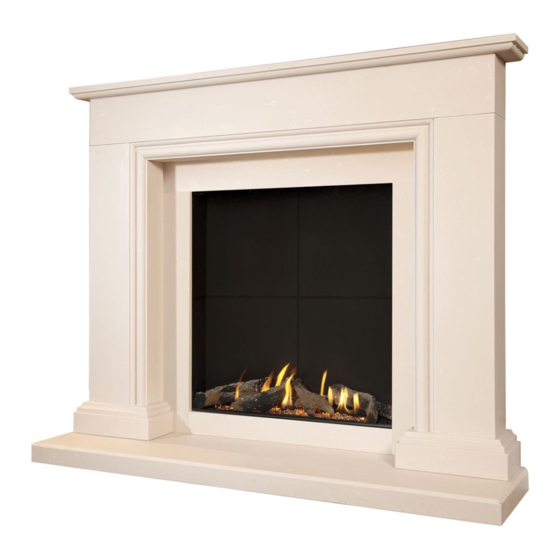
Page 37: Important Safety Information
ABOUT YOUR NEW SOPHIA GAS FIRE The Flavel Sophia log effect gas fires incorporate a unique and highly developed fuel bed which gives the realism of a loose log layout combined with realistic flames and glow. The use of durable ceramic material in the construction of the fuelbed components ensures long and trouble free operation. - Page 38 LIGHTING THE FIRE / USER CONTROLS IMPORTANT : IF THE BURNER IS EXTINGUISHED FOR ANY REASON YOU MUST ENSURE THAT YOU WAIT A FULL THREE MINUTES BEFORE ATTEMPTING TO RE-LIGHT THE FIRE. The product is controlled by the remote handset supplied with the fire. Ensure the 1 off 9V PP3 battery as supplied in the loose items pack has been fitted to the remote handset before attempting to use the handset.
- Page 39 Fig. 2 Manual Graphic on Handset Display 5.3.1.3 With the product in “MANUAL” mode the fire can now be switched between HIGH rate heat input and LOW rate heat input by pressing the “DOWN” arrow on the handset. To reduce the flame height of the main burner incrementally, press the arrow momentarily.
- Page 40 5.3.2 Operation of the Fire in “TEMPERATURE” mode 5.3.2.1 In order to change the mode of operation from “MANUAL” to “TEMPERATURE”, press the “SET” button, the fire will then change to either “DAY TEMP” (figure 4) mode or “NIGHT TEMP” mode (figure 5). To alternate between the 2, press the “SET”...
- Page 41 5.3.3 Operation of the Fire in “TIMER” mode 5.3.3.1 In order to change the mode of operation from “MANUAL” to “TIMER”, press the “SET” button, the fire will then alternate between the settings until the “TIMER” mode is displayed. NOTE : The “SET” button allows you to alternate between all modes of operation :- “...
- Page 42 5.3.4 Low Battery Signal 5.3.4.1 When the battery in the handset needs replacing, “BATT” will be displayed on the handset. 5.3.4.2 Remove the cover on the rear of the handset and replace the 1 off 9V battery as necessary.
-
Page 43: Conditions Of Installation
REMOVAL / RE-FITTING THE GLASS FRAME ASSEMBLY 5.4.1 Remove the glass panel by firstly affixing the glass clamp to the glass panel as shown below in figure 8. Fig. 8 5.4.2 Remove 5 off screws which hold the lower retaining bracket in position. -
Page 44: About Your New Fire
5.4.3 Unhook the glass panel from the top retaining channel by lifting upwards then tilt the top edge of the glass assembly towards you as shown below in figure 10 (sectional view through product for clarity). Fig. 10 5.4.3 Remove the glass frame assembly by sliding to the left until the right hand edge of the glass frame can be released from behind the right hand leg of the surround as shown below in figure 11 and overpage in figure 12. -
Page 45: Operating The Fire
Fig. 12 R/H edge of glass frame 5.4.4 Store the glass frame assembly in a safe place. 5.4.5 Re-assemble in reverse order when re-fitting the glass assembly. Ensure that the glass assembly is correctly located on the top flange of the combustion chamber, this can be achieved by putting your hand onto the top edge of the glass frame inside the convection air aperture and pushing down firmly to check the glass frame is correctly located. - Page 46 RE-LAYING THE FUEL-BED 5.5.1 Lay an even layer of vermiculite material across the burner tray as shown below in figure 13. Fig. 13 5.5.2 Place log “A” in a central position as shown below in figure 14, using the location hole on the base of the log to position in line with the location peg on the burner.
- Page 47 5.5.3 Place log “B” in position at the left hand side of the burner as shown below in figure 15, using the cut out on the left hand side of log “A” as a guide for placement and the locating lug at the LHS of the fuel tray. Fig.
- Page 48 5.5.5 Place log “D” in position at the centre left hand side of the burner as shown below in figure 17, using the locating peg at the front of the burner and positioning on log “A” as shown. Fig. 17 Log D 5.5.6 Place log “E”...
- Page 49 5.5.7 As a final check ensure that the logs are layed correctly as shown below in figure 19. Fig. 19 Log A Log E Log B Log C Log D 5.5.8 If required fit the embaglow material over the flame ports. To do this seperate into short strands and place randomly over the flame porting area as indicated by the arrows below in figure 20.
- Page 50 5.5.9 Re-fit the glass frame assembly before proceeding. Warning : Use only the log fuel-bed supplied with the fire. When replacing the log fuel-bed remove the old log fuel-bed and discard it. Fit a complete log fuel-bed from the manufacturer, only use genuine replacements. THE FOLLOWING STATEMENT IS APPLICABLE TO ALL FUEL-BED TYPES This appliance uses fuel effect pieces containing Refractory Ceramic Fibres (R.C.F.), which are man-made vitreous silicate fibres.
-
Page 51: User Replaceable Parts
5.6 (CONT.) CLEANING THE FUELBED We do not recommend cleaning of the logs or fuelbed components as these are fragile and damage may result. None of these parts must be washed or exposed to any cleaning agents or water. Any damaged parts must be replaced by contacting your dealer or telephoning BFM Europe Ltd. - Page 52 Due to our policy of continual improvement and development the exact accuracy of descriptions and illustrations cannot be guaranteed. Part No. B-1004690 Issue 1 BFM Europe Ltd. Trentham Lakes Stoke-on-Trent Staffordshire ST4 4TJ www.bfm-europe.com Telephone - General Enquiries : (01782) 339000 Telephone - Service : (01782) 339008...
Need help?
Do you have a question about the Sophia Simline BF and is the answer not in the manual?
Questions and answers