Table of Contents

Subscribe to Our Youtube Channel
Related Manuals for Flavel Curve


Summary of Contents for Flavel Curve
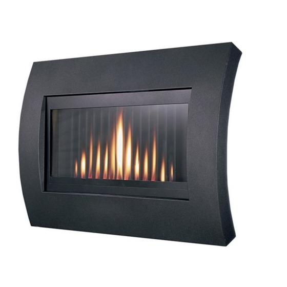
- Page 1 Curve RADIANT FLAME EFFECT GAS FIRE Installation and Maintenance Instructions Hand these instructions to the user Model No’s FCRR**RN is for use on Natural Gas (G20) at a supply pressure of 20 mbar in G.B. / I.E. NB: “**” refers to fascia variant...
-
Page 2: Table Of Contents
Assembling Fuel Bed and Commissioning Lighting the appliance 16-17 Checking for clearance of combustion products Fixing the “Curve” Fascia in position Removal & re-fitting of the glass frame assembly Section 4 Maintenance Removal of the Burner Assembly Removal of the Valve / Solenoid 21-22 Removal of the Pilot Assy. -
Page 3: Information And Requirements
SECTION 1 INFORMATION AND REQUIREMENTS APPLIANCE INFORMATION Model FCRR**RN “**” denotes fascia variant Gas Type Main injectors (1 off) Size 380 Pilot Type Copreci 21100 / 141 Max. Gross Heat Input : 6.5 kW Min. Gross Heat Input : 3.5 kW Cold Pressure : 20.0 +/-1.0 mbar Ignition :... -
Page 4: Conditions Of Installation
INSTALLATION REQUIREMENTS CONDITIONS OF INSTALLATION It is the law that all gas appliances are installed only by a CORGI Registered Installer, in accordance with these installation instructions and the Gas Safety (Installation and Use) Regulations 1998 as amended. Failure to install appliances correctly could lead to prosecution. -
Page 5: Fireplace / Surround Suitability
FIREPLACE / SURROUND SUITABILITY This fire can be installed with a fire surround in a conventional type installation (see page 11 for dimensional information) or without a fire surround, for a hang on the wall type installation. It must not be installed directly onto carpet or other combustible floor materials. -
Page 6: Chimney Opening / Catchment Space
There must be no leakage of smoke through the structure of the chimney during or after the smoke pellet test and it is important to check inside upstairs rooms adjacent to the chimney / flue. Check the chimney pot / terminal and general condition of the brickwork or masonry. - Page 7 Table A - Installation Depth Requirements for a Flavel Curve being installed into a brick built chimney, requiring 12.0 litres of debris collection volume (fig. 2). When installing this product into a builders opening / brick-built chimney, the depth required is a minimum of 156mm. The 12.0 litres of debris collection volume is achieved by the space available below the flue spigot.
-
Page 8: Precast Flues
If fitting without a hearth panel, this appliance must only be installed at a minimum height to the base of the opening of 160mm above the floor level, (measured from the bottom edge of the “Curve” fascia) e.g. above the level of the carpet or floor covering. -
Page 9: Spillage Monitoring System
1.10 SPILLAGE MONITORING SYSTEM This appliance is fitted with an atmosphere sensing spillage monitoring system in the form of an oxygen sensing pilot. This is designed to shut the fire off in the event of a partial or complete blockage of the flue causing a build up of combustion products in the room in which the fire is operated. -
Page 10: Installation Of Fire
4off AA Batteries 1 off 6mm Allen key 1 off each User instruction book and Installation book 1 off Curve Fascia 1 off Closure Plate INSTALLING THE COMBUSTION CHAMBER & CLOSURE PLATE Establish which type of flue you are intending to install the fire in to :-... -
Page 11: Preparation Of The Flue Opening
PREPARATION OF THE FLUE OPENING If installing the product into a wall mounted installation, create an opening as shown in Fig. 3 below. If installing into a conventional opening with a hearth panel, create an opening as shown in Fig. 4 below. Fig. - Page 12 Proceed as follows :- Prepare the mounting holes on the wall to which the fire is to be fitted. See Fig. 5 below. Fig. 5 550mm CRS Diameter 34mm Spigot Mounting holes for combustion chamber Fire Opening Closure Plate Centre the closure plate around the fireplace opening and mark the positions of the mounting holes as shown above in fig.
- Page 13 Fig. 6 Spigot Fire Opening 460mm Closure Plate Gas Supply Restrictor / PTP Elbow 128mm Note : Before breaking into the gas supply a tightness test should be carried out to establish that the existing pipework is sound. Before making the final gas connection, thoroughly purge the gas supply pipework to remove all foreign matter, otherwise serious damage may be caused to the gas control valve on the fire.
-
Page 14: Fitting The Batteries To The Receiver Unit
FITTING THE BATTERIES TO THE RECEIVER UNIT 4 off AA 1.5V batteries (found in the loose items pack) are to be fitted to the battery holder located centrally on the fire, below the combustion chamber as shown below in Fig. 7. Fig. -
Page 15: Gas Tightness And Inlet Pressure
GAS TIGHTNESS AND INLET PRESSURE Remove the pressure test point screw from the inlet elbow and fit a manometer. Turn on the main gas supply and carry out a gas tightness test. Depress both the round buttons on the handset. The fire will then commence its ignition sequence and will light to high. -
Page 16: Lighting The Appliance
SECTION 3 COMMISSIONING OF THE FIRE LIGHTING THE APPLIANCE The control valve is positioned on the left hand side of the fire when viewed from the front. To operate the appliance automatically via the remote control handset, ensure that the on / off switch is switched to the “on” position as shown below in Fig. - Page 17 Fig. 12 “LED” handset light “UP” button “DOWN” / “STANDBY” “STAR” / “OFF” button button The fire can now be switched between HIGH rate heat input and LOW rate heat input by pressing the “DOWN” arrow on the handset. To reduce the flame height of the main burner incrementally, press the arrow momentarily.
-
Page 18: Checking For Clearance Of Combustion
CHECKING FOR CLEARANCE OF COMBUSTION PRODUCTS Close all doors and windows in the room. Light the fire and allow to run for approximately 5 minutes on high position. After approximately 5 minutes hold a smoke match as shown at the lower front edge of the draught divereter, as shown below in Fig. - Page 19 FITTING THE “CURVE” FASCIA The “Curve” fascia is fitted to the product by hooking the top edge of the fascia over the mounting brackets as shown in Fig. 14 below, then securing with two screws on the bottom face of the trim as shown in Fig.
-
Page 20: Removal & Re-Fitting Of The Glass Frame Assembly
REMOVAL & RE-FITTING OF THE GLASS FRAME & PANEL Remove the “Curve” fascia by unscrewing the retaining screws and lifting the “Curve” fascia off the brackets, in the reverse order as detailed in section 3.3, on page 18 The glass frame is then removed by using the 6mm allen key supplied to unscrew the 4 off allen bolts (Fig. -
Page 21: Maintenance
4.1.5 To refit the burner assembly, replace in reverse order and re-fit the glass frame assembly as shown in section 3.4 on page 20 and the “Curve” fascia as described in section 3.3 on page 19. Removing the Valve 4.2.1... -
Page 22: Removal Of The Pilot Assy
4.2.5 Remove the valve retaining screws and remove the valve. Re-assemble in reverse order and carry out a gas tightness test. Re-fit the “Curve” fascia as described in section 3.3 on page 19. Removing the Pilot Assembly. Note : Because this appliance is fitted with an atmosphere sensing ‘Oxy- Pilot’... -
Page 23: Parts Shortlist
PARTS SHORTLIST Replacement of any other parts must be carried out by a competent person such as a CORGI registered gas installer. The part numbers of the replaceable parts are as follows, these are available from BFM Europe, contact details as shown below.
Need help?
Do you have a question about the Curve and is the answer not in the manual?
Questions and answers
Flavel Curve After resetting it won't light even after repeating to relight
The Flavel Curve may not light after resetting because the instructions state that after the pilot flame has been extinguished, you must wait at least three minutes before trying to relight the fire. Attempting to relight it too soon can prevent successful ignition.
This answer is automatically generated
After resetting it won't light tried repeatedly but still won't light
The Flavel Curve may not light after resetting due to a faulty gas valve. An engineer suspected the gas valve was the issue after multiple parts were replaced and the problem persisted.
This answer is automatically generated