
Related Manuals for Flavel Emberglow Classic RC


Summary of Contents for Flavel Emberglow Classic RC
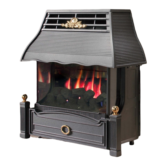
- Page 1 EMBERGLOW CLASSIC RC RADIANT CONVECTOR GAS FIRE Installation, Maintenance & User Instructions Hand these instructions to the user Model No. FEMC00RN is for use on Natural Gas (G20) at a supply pressure of 20 mbar in G.B. / I.E.
-
Page 2: Table Of Contents
CONTENTS Contents Installation Instructions Page Appliance Data Section 1 Conditions of Installation. Flue & Chimney Suitability Fireplace/Surround Suitability Shelf Position Side Clearance Closure Plate Flue & Chimney inspection Chimney Catchment space 1.8.1 Brick Built Chimney 1.8.2 Fitting to Pre-Fab. Twin Wall Metal Flueboxes 1.8.3 Fitting to Pre-Cast Flue Installations Hearth Fitting... -
Page 3: Appliance Data
APPLIANCE DATA G20 Models Main injector (1 off) Stereomatic size 360 Cat 82 Pilot Type. Copreci Single Flame Type 21100 / 162 Max. Gross Heat Input : 6.0 kW Min. Gross Heat Input : 1.8 kW Cold Pressure : 20.0 +/- 1.0 mbar (8.0 +/- 0.4 in w.g.) Ignition : 9V battery / electronic ignition Electrode Spark Gap :... -
Page 4: Conditions Of Installation
CONDITIONS OF INSTALLATION In Great Britain :- It is law that all gas appliances are installed only by a CORGI registered installer in GB, in accordance with these installation instructions and the Gas Safety (Installation and use) Regulations 1998. Failure to install appliances correctly could lead to prosecution. -
Page 5: Fireplace/Surround Suitability
FIREPLACE / SURROUND SUITABILITY The fire is suitable for hearth mounting or wall mounting. It must not be fitted directly onto a carpet or other combustible material. It must not be fitted to combustible walls. This fire is suitable for the following hearth / surround types: Non-combustible hearths / surrounds. -
Page 6: Chimney Catchment Space
Brick / stone built chimneys and any chimney or flue which has been used for an appliance burning fuel other than gas must be thoroughly swept. The base of the chimney / flue must also be thoroughly cleared of debris etc. Any under floor air supply to the fireplace must be completely sealed off. -
Page 7: Metal Flueboxes
The front opening of the fireplace must be between 305mm and 440mm wide, and between 500mm and 650mm high. If the opening is larger than this, then a surround must be constructed in a suitable non-com bustible material to create an opening to these limits. Allow a minimum flat surface of 20mm around the opening to ensure that the closure plate can be sealed to the fireplace. -
Page 8: Fitting To Pre-Cast Flue Installations
1.8.3 Fitting to Pre-Cast Flue Installations. The pre-cast opening must be a minimum of 122.7cm 2 or equivalent cross-sectional area and have a minimum effective flue height of 3 metres. This appliance has been tested for use in a pre- cast flue block complying with BS EN 1858. -
Page 9: Packing Check List
PACKING CHECK LIST 1 off Cast Canopy 1 off Firebox / Burner Assembly 1 off Flue Spigot 1 off Closure Plate 1 off Literature / Loose Items Pack 1 off Fuelbed 1 off Coal Pack 1 off Cast Fender 1 off Remote Handset INSTALLATION OF FIRE 2.2.1 Preparation. -
Page 10: Closure Plate Fitting
2.2.2 Closure plate fitting Fit the closure plate to the fireplace opening and ensure that it has a flat sealing area of at least 10mm sealed on all sides. See Fig. 3 below Dimensions stated are for closure plate supplied Check the operation of the chimney as follows:- Fig. -
Page 11: Fitting Canopy Rear Trim
FITTING THE CANOPY REAR TRIM Secure the canopy rear trim to the canopy via the four fixings screws (2 off L/H & 2 off R/H) as shown below in Fig. 4 Fig. 4 2 off R/H Fixing Screws FITTING THE CANOPY TO THE FIREBOX Secure the canopy to the firebox with the four screws (2 off L/H &... -
Page 12: Fitting Spigot To Firebox
FITTING THE SPIGOT TO THE FIREBOX Screw the firebox spigot to the draught diverter with the four screws, 2 off upper (as shown below in Fig. 6) & 2 off lower screws (not pictured) . Fig. 6 4 off Flue Spigot Fixing screws Note : A means of isolation must be provided near to the appliance to facilitate... -
Page 13: Assembly Of Fuelbed
ASSEMBLY OF THE FUELBED NOTE : The position of the fuel-bed components are critical to the performance of the product. Therefore please ensure that the fuel-bed components are positioned as described in the following section prior to requesting a service call due to soot build up, poor flame pattern etc. Fit the fuelbed base into the combustion chamber as shown below in Fig. - Page 14 Fit coal “B” onto the fuelbed base in the position as shown below in Fig. 9. The coal form has the individual placement letters stamped on the bottom face. Fig. 9 Coal Form “B” Fit coal “C” onto the fuelbed base in the position as shown below in Fig.
- Page 15 Fig. 11 Coal Form “D” Fit coal “E” onto the fuelbed base in the position as shown below in Fig. 12. The coal from has the individual placement letters stamped on the bottom face. Fig. 12 Coal Form “E” To ensure that the release of fibres from these R.C.F (Refractory Ceramic Fibre) articles is kept to a minimum, during installation and servicing we recommend that you use a HEPA filtered vacuum to remove any dust accumulated in and around the appliance before and after working on the...
-
Page 16: Connecting The Battery Pack
CONNECTING THE BATTERY PACK To prevent un-necessary battery drain, the battery pack that is used to power the remote control function for this product is disconnected at the factory. Prior to attempting to light the product, can the installer please ensure that the battery pack is re-connected as described in section b), c) &... -
Page 17: Fixing The Infrared Sensor In Position
FIXING THE INFRARED SENSOR IN POSITION The infrared sensor is supplied from the factory attached to a self adhesive pad. This pad can therefore be attached to the hearth in a position to suit the form of the ashpan that is supplied with the product Fig. -
Page 18: Lighting The Appliance
LIGHTING THE APPLIANCE The Remote control handset generates an infrared signal, which will be received by the sensor situated at the front right of your fire, behind the black ashpan cover. This infrared signal requires direct line of sight from the handset to the sensor on the fire to ensure good operation. To light the appliance using the handset, point the handset at the fire and press the 2 left hand buttons together. -
Page 19: Checking For Clearance Of Combustion
IMPORTANT: THE FIRE MUST ONLY BE OPERATED WITH THE FRONT CASTING IN PLACE CHECKING FOR CLEARANCE OF COMBUSTION PRODUCTS Close all doors and windows in the room. Light the fire and turn to the maximum position. After 5 minutes hold the smoke match as shown in Fig. 17 below. Whilst holding the smoke match in the correct position, approximately 25mm below the lower edge of the draught diverter, ensure that most of the smoke is drawn into the flue aperture. -
Page 20: Final Checks
FINAL CHECKS Recheck the operation of the fire on all settings. Make sure that the user knows how to operate the fire and refer them to the user book. Inform the User that the Model Number for ordering parts is shown on the rating plate. -
Page 21: Maintenance Instructions
MAINTENANCE INSTRUCTIONS Servicing Notes Servicing should be carried out annually by a competent person such as a registered engineer, and must include changing the oxypilot. This is a condi- tion of the manufacturers guarantee. The service should include visually checking the chimney and fire opening for accumulations of debris and a smoke test to check for positive up-draught in the chimney. -
Page 22: Removal Of The Control Tap
Fig. 19 2 off R/H Burner Retaining Screws 2 off L/H Burner Retaining Screws Remove the four burner retaining screws as indicated in Fig. 19 above Slide the burner assembly to the right, off the injector and remove the from the firebox. REMOVING THE CONTROL VALVE FROM THE FIRE Disconnect the appliance from the gas supply. -
Page 23: Removal Of The Control Board
REMOVING THE CONTROL BOARD Disconnect the appliance from the gas supply. Remove the glass front panel as descibed on page 9, (fig. 2) Remove the coals and fuel-bed matrix. Pull the fire forwards and tilt fire onto its back to allow access to control board underneath (situated in centre). - Page 24 EMBERGLOW CLASSIC RC RADIANT CONVECTOR GAS FIRE User Instructions This section of the instructions should be read by the user before operating the appliance and retained for future reference Model No. FEMC00RN is for use on Natural Gas (G20) at a supply pressure of 20 mbar in G.B.
-
Page 25: Installation Information
INSTALLATION INFORMATION CONDITIONS OF INSTALLATION It is the law that all gas appliances are installed only by a competent (e.g. CORGI Registered) Installer, in G.B. in accordance with the installation instructions and the Gas Safety (Installation and Use) Regulations 1998. Failure to install appliances correctly could lead to prosecution. - Page 26 ABOUT YOUR NEW FLAVEL EMBERGLOW GAS FIRE The Flavel Emberglow gas fire incorporates a unique and highly developed heat exchanger which combined with the coal effect gives maximum heat whilst maintaining reasonable running costs Please take the time to fully read these instructions as you will then be able to obtain the most effective and safe operation of your fire.
- Page 27 OPERATING THE FIRE The Remote control handset generates an infrared signal, which will be received by the sensor situated at the front right of your fire, behind the black controls cover. This infrared signal requires direct line of sight from the handset to the sensor on the fire to ensure good operation. To light the appliance using the handset, point the handset at the fire and press the 2 left hand buttons together.
- Page 28 TURNING THE PRODUCT OFF IN THE UNLIKELY EVENT OF A REMOTE HANDSET MALFUNCTION. In the unlikely event of the remote control handset malfunctioning (or if lost or broken) after the appliance has been turned on, the fire can be turned off via the emergency shut off switch on the right hand control panel. Press and hold the emergency shut off switch until the fire shuts down.
- Page 29 SPILLAGE MONITORING SYSTEM This appliance is fitted with a spillage monitoring system which shuts down the fire if the evacuation of combustion products from the fire is affected by a partially or fully blocked flue. If this system operates the fire will go out. If this occurs, leave the fire for at least three minutes then follow the lighting procedure as described in the previous section.
- Page 30 ASSEMBLY OF THE FUELBED NOTE : The position of the fuel-bed components are critical to the performance of the product. Therefore please ensure that the fuel-bed components are positioned as described in the following section prior to requesting a service call due to soot build up, poor flame pattern etc. Fit the fuelbed base into the combustion chamber as shown below in Fig.
- Page 31 Fit coal “B” onto the fuelbed base in the position as shown below in Fig. 5 The coal form has the individual placement letters stamped on the bottom face. Fig. 5 Coal Form “B” Fit coal “C” onto the fuelbed base in the position as shown below in Fig.
- Page 32 To ensure that the release of fibres from these R.C.F (Refractory Ceramic Fibre) articles is kept to a minimum, during installation and servicing we recommend that you use a HEPA filtered vacuum to remove any dust accumulated in and around the appliance before and after working on the appliance.
Need help?
Do you have a question about the Emberglow Classic RC and is the answer not in the manual?
Questions and answers